Proceeding Paper

Numerical Simulations on Heat Transfer Enhancement of Nanofluids in Microchannel Using Vortex Generator †

Department of Mechanical Engineering, Chung Yuan Christian University, Taoyuan 32023, Taiwan
*
Author to whom correspondence should be addressed.
Presented at the 3rd IEEE International Conference on Electronic Communications, Internet of Things and Big Data Conference 2023, Taichung, Taiwan, 14–16 April 2023.
Eng. Proc. 2023, 38(1), 68; https://doi.org/10.3390/engproc2023038068
Published: 29 June 2023

Abstract

:
Vortex-induced vibration (VIV) is the periodic motion of a bluff body caused by fluid flow and is widely discussed in the engineering field. With the advancement of science and technology, miniaturization and integration have become the mainstream trends in biomedical chips and electronic systems, resulting in higher heat dissipation requirements per unit area. Therefore, the improvement of the heat dissipation effect of movable structures in the flow channel has been widely discussed. Among them, adding VIV motion in the microchannel generates a vortex structure, which improves heat transfer efficiency. Different from the direct displacement method of active vibration, the passive displacement of VIV is a multi-physics problem. It needs to integrate the flow field and the spring-mass system of the object for fluid–solid coupling, which greatly increases the difficulty of analysis. In this study, the Immersed-boundary method (IBM) combined with the equation of motion is used to numerically study a vortex generator that is elastically installed in a microfluidic channel and is then used to enhance the convective heat transfer of nanofluids in the channel. Unlike the common body-fitted mesh, IBM greatly reduces the computational resources required for mesh regeneration when simulating the problem of object movement in fluid–structure interaction. In addition, Buongiorno’s two-phase mixing model is used to simulate the convective heat transfer of nanofluids in microchannels by considering the Brownian motion and thermophoretic diffusion of nanoparticles in the carrier liquid. By changing the important parameters such as nanofluid concentration, Reynolds number, mass ratio, and Ur, the influence of the response characteristics of vortex-induced vibration on the heat flow field in the microfluidic channel is discussed, and the key factors for enhancing heat transfer are found out.

1. Introduction

With the advancement of science and technology, miniaturization and integration have become the mainstream trends in biomedical chips and electronic systems. As biochips are designed and manufactured with the principles of microelectromechanical systems combined with biochemistry and bioinformatics, the advantages of biochips are similar to computer chips. Both complete a large amount of calculation and analysis in a short time, but the disadvantages are similar. That is, with the miniaturization of the motor system, the heat dissipation demand per unit area becomes higher [1]. Therefore, with the improvement of the micro heat exchange, heat dissipation efficiency has been discussed recently. There are many ways to improve heat dissipation efficiency, such as adding fans to increase the flow of the working fluid, adding cooling fins to increase the contact area, and replacing the radiator or working fluid with materials with high thermal conductivity. However, adding devices such as fans or fins increases the volume and weight of the product, which is contrary to the recent trend of shrinking electronic components. Micro-channels solve the above problems. A micro-channel heat sink (MHS) is one of the heat exchange technologies proposed by Tuckerm and Pease [2] to solve the heat dissipation problem of very large-scale integration (VLSI). This technology is now widely used in MEMS.
In addition to the micro-channel radiator that can improve heat transfer efficiency, adding a fixed or movable object in the micro-channel can increase the turbulent flow to mix the fluid on the boundary layer and promote the destruction of the thermal boundary layer (TBL). Yeom et al. [3] used piezoelectric stacked actuators to vibrate objects within the flow channel to enhance convective heat transfer on the flow channel wall. At the same time, the destruction of this TBL is similar to the effect of actively oscillating cylinders on heat transfer enhancement in the flow channel oscillation [4], which has a significant effect on the heat transfer enhancement of the wall. Celik [4] also mentioned that when the cylinder oscillates in the cross-flow direction at a frequency close to the natural vortex shedding frequency, the vortex shedding is synchronized with the cylinder motion. This synchronization is called Lock-in. Kumar et al. [5] also studied the effect of oscillating cylinders on enhanced heat transfer in the flow channel. However, the movement method of the movable cylinder studied by Kumar is passive. The effect of the periodic oscillation of the object on the heat dissipation of the wall is observed by changing the reduced velocity. The effect of the periodic oscillation of the object on the heat dissipation of the wall is observed by changing the reduced velocity. Compared with the active type, the passive type does not require other actuators or equipment, but simple passive elements such as springs and damping can make the cylinder perform the periodic motion. The periodic motion of this type of bluff body caused by the flow of fluid is called vortex-induced vibration. Different from the direct displacement method of active vibration, the passive displacement of VIV is a multi-physics problem. It is necessary to integrate the flow field and the spring-mass system of the object for fluid–solid coupling and greatly increases the difficulty of analysis.
The vortex shedding of a stationary cylinder is greatly affected by the Reynolds number. Lienhard [6] described the state of vortex shedding at various Reynolds numbers. When Re < 5, the fluid detaches from the surface of the cylinder and flows along the contour of the cylinder. When 5 ≤ Re < 45, the fluid starts to fall off from the back of the cylinder, forming a pair of symmetrical vortices. When 45 ≤ Re < 150, the vortices start to fall off periodically from both sides. All are still laminar flow; until 150 ≤ Re < 300, the fluid is still laminar at the cylinder boundary. However, the shed wake becomes turbulent, and Re ≥ 300 is completely turbulent. Zhao [7] studied the flow of elastically mounted cylinders at different Reynolds numbers through three-dimensional simulations. When Re = 250, the wake of the vibrating cylinder is two-dimensional, and when Re = 300, it is three-dimensional. We assume that the two are laminar flows between plates. From the above-mentioned Reynolds number setting and laminar turbulence change, Re is set as 100.
The above-mentioned active or passive cylindrical vibration heat dissipation uses pure fluid. However, with the advancement of science and technology, electronic equipment has increased heating power, reduced volume, and reduced working space with fluids. The thermal conductivity of pure fluids can no longer meet the heat dissipation needs of today’s electronic components. Thus, we add tiny solid particles into the fluid to form nanofluids by combining the good thermal conductivity of solids with the convection properties of fluids, thereby improving the overall heat transfer efficiency. With Buongiorno’s two-phase model [8], the convective heat transfer of the nanofluid in a microchannel is simulated. By changing, we can observe the effect of amplitude on heat transfer.

2. Materials and Method

The schematic diagram of the system considered in this study is shown in Figure 1. The model is a two-dimensional double-plate flow, which contains a passive vortex generator. D is the diameter of the vortex generator at 7.5 × 10⁻⁵ m, the inlet condition is a fully developed flow, the temperature is 293 K, and the flow velocity distribution is in Ref. [5]. The lower wall has a section of heat generator whose temperature is 373 K, and the rest of the walls are adiabatic. In contrast, the diameter of the vortex generator is 7.5 × 10⁻⁵ m, the nanofluid is mainly composed of basic fluid (water) and nanoparticles ( Al 2 O 3 ), and the selected force is 25 nm with the basic properties proposed by Lao [9].
In this study, a non-uniform grid is used to simulate the heat transfer characteristics of nanofluid in the flow channel, and the finite-volume method discretized in Cartesian coordinates is used to solve the flow field and thermal field. In order to deal with the motion of the vortex generator that is elastically installed in the microfluidic channel, we adopt the Immersed-boundary method (IBM) [10] combined with the equation of motion to deal with the interaction between the fluid and the solid. IBM computes the velocities of adjacent grid points outside the solid region through linear difference. Different from the common body-fitted mesh, the computational resources required for mesh regeneration can be greatly reduced when simulating the problem of object movement in fluid–structure interaction. The flow boundary condition is applied at the structural boundary to study the effect of the vortex generator on the heat transfer and flow of the nanofluid in the flow channel. Thermophoresis and Brownian motion of nanofluid are considered in the Boungiorno two-phase model. The fluid is assumed to be a Newtonian, viscous incompressible fluid, and the flow field is laminar, unsteady, and two-dimensional.
According to the above conditions, the governing equation includes the continuity equation, the momentum equation, the energy equation, and nanoparticle transport (volume fraction of nanoparticles) equations [9]
ρ n f u x + ρ n f v y = 0
ρ n f ( u u x + v u y ) = p x + μ n f ( 2 u x 2 + 2 u y 2 ) + f M x
ρ n f ( u v x + v v y ) = p y + μ n f ( 2 v x 2 + 2 v y 2 ) + g ( ρ β ) n f ( T T c ) + f M y
u T x + v T y = α n f ( 2 T x 2 + 2 T y 2 ) + f E
u φ x + v φ y = [ x ( D B φ x ) + y ( D B φ y ) ] + [ x ( D T T x ) + y ( D T T y ) ] + f C
where x , y are the Cartesian coordinates in x and y directions, u , v is the velocity components in x and y directions, p is the pressure, g is the gravitational acceleration, α n f is the thermal diffusivity of the nanofluid, T is the temperature, φ is the nanoparticle volume fraction, D B is the Brownian coefficient, D T is the thermophoresis coefficient, f M x , f M y is the discrete-time momentum forcing in x and y directions, f E is the discrete-time energy forcing, f C is the discrete-time volume fraction forcing. ρ n f , β n f , ( C p ) n f , the effective density, the thermal expansion coefficient, and the thermal diffusivity of the nanofluid are obtained as follows.
ρ n f = ( 1 φ ) ρ f + φ ρ p
( ρ β ) n f = ( 1 φ ) ( ρ β ) f + φ ( ρ β ) p
( ρ c p ) n f = ( 1 φ ) ( ρ c p ) f + φ ( ρ c p ) p
where μ n f , k n f are the effective viscosity and the thermal conductivity of the nanofluid, respectively, and are predicted by the experiments-based empirical correlations [11]. The effective viscosity and thermal conductivity of the carrier liquid are obtained from the equations studied by Meis et al. [12].
μ n f μ f = 1 1 34.87 ( d p / d f ) 0.3 φ 1.03
μ f = 1 1.1292 T + 0.4904 T 2
k n f k f = 1 + 4 . 4 Re 0.4 Pr 0.66 ( T T f r ) 10 ( k p k f ) 0.03 φ 0.66
k f = 1 + 0.1572 T 0.0470 T 2
As presented in Equation (5), the slip mechanisms of Brownian motion and thermophoresis are included to mimic the interaction between the nanoparticles and the based fluid, where the Brownian diffusion coefficient ( D B ) and thermophoresis coefficient ( D T ) are defined in Ref. [8].
D B = k b T 3 π μ f d p
D T = 0.26 k f 2 k f + k p μ f ρ f T φ
The undamped spring-mass system is constrained to one translational degree of freedom motion (in the vertical direction). The dynamics of this system are governed by the following equation [5]:
Y + 4 π 2 U r 2 Y = C L 2 M
where C L and M is the lift coefficient and mass ratio.

3. Result and Discussion

3.1. Code Validation and Mesh Independence Studies

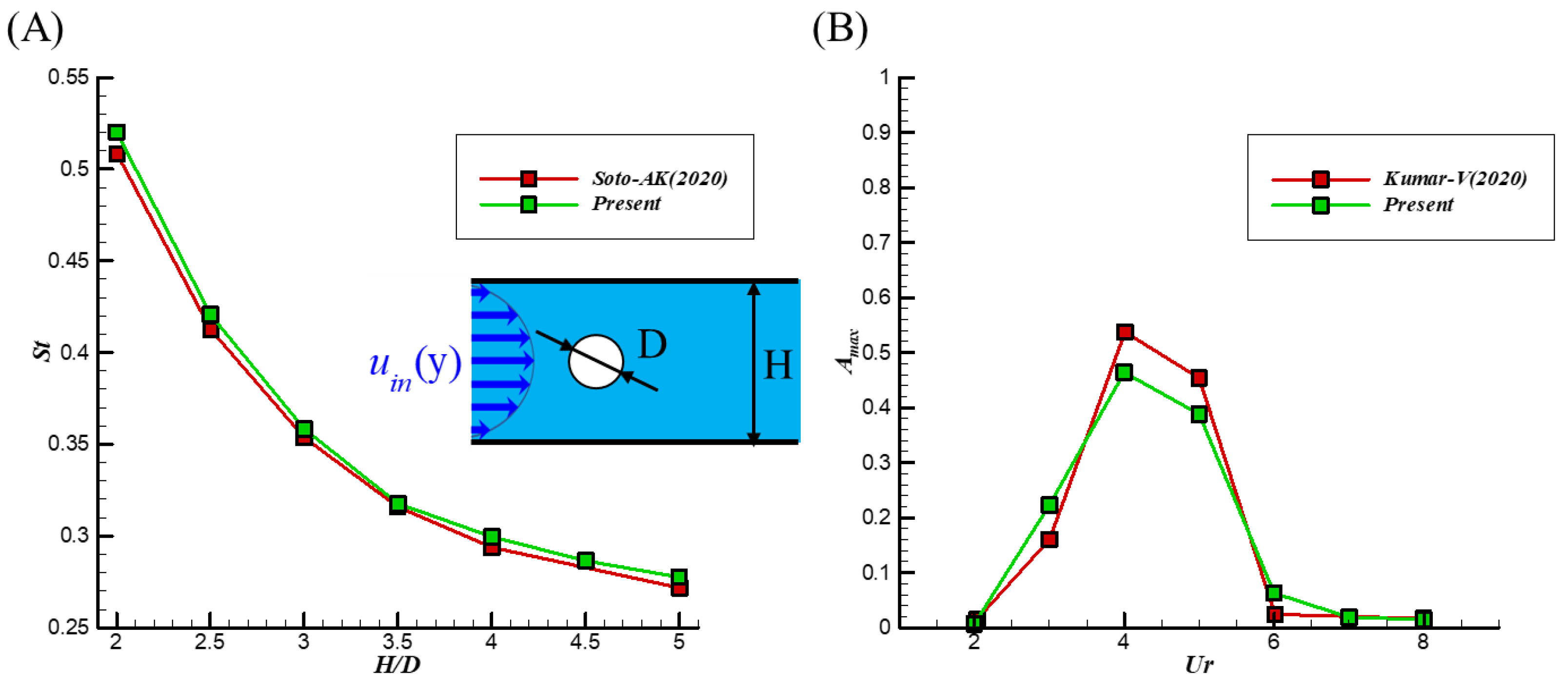
In order to determine the correctness of the current simulation, the current simulation results are compared with the simulation of a stationary cylinder [13] and the simulation [5] of an elastically mounted cylinder [5].
Figure 2A shows the simulation data of Soti et al. [13] compared with the current simulation results. The results of this study are in good agreement with Soti’s. Figure 2B shows the variation in maximum oscillation amplitude ( A max ) for an elastically mounted cylinder with U r as for Kumar et al. [5]. Figure 2B also presents that the Lock-in range in this study ( A max > 0.1 ) is similar to Kumar, as both are in 3 U r 5 . ( A max is dimensionless by the diameter of the cylinder).
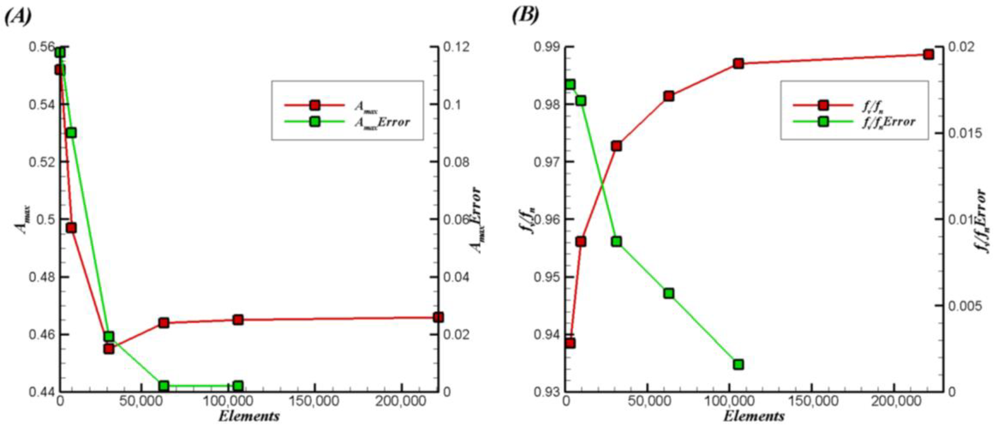
A mesh independence study is then performed by using the Kumar domain [5]. The computational domain uses a combination of a uniform mesh of size Δx = Δy (covering the area around the cylinder) and a non-uniform stretched mesh (covering the rest of the domain). Mesh independence studies were performed by changing the mesh size ΔX = Δx/D to 1/5 (3116), 1/10 (9590), 1/20 (31,122), 1/30 (63,012), 1/40 (105,564), and 1/60 (221,028) in a uniform mesh area. Figure 3 shows the maximum amplitude A max and frequency ratio ( f v / f n ) for cylinders U r = 4 of six mesh sizes. A mesh size of ΔX = 1/30 was chosen for the simulation because refinement beyond 1/30 did not change the maximum oscillation amplitude and frequency ratio by more than 1%. ( f v and f n is vortex shedding frequency of vibrating cylinder and natural frequency of cylinder).

3.2. Result

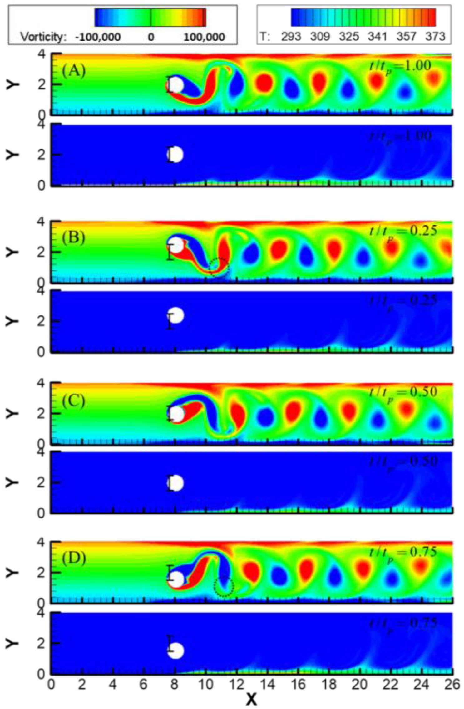
Figure 4 shows the vorticity and isotherm diagrams in t / t p = 1.00 , t / t p = 0.25 , t / t p = 0.50 , t / t p = 0.75 , by observing the movement of the cylinder in the flow channel under the conditions of U r = 3 , φ = 0 % . In Figure 4A,B, at t / t p = 1.00 , the thermal plume structure and the vortex structure are located at equal positions, and it is inferred that the TBL is destroyed due to the interaction with the convective vortex. The same goes for the remaining t / t p because the eddies periodically pass through the TBL, forcing the fluid near the TBL to exchange towards the middle, destroying the TBL and ultimately improving heat transfer ( t , t p is time, time period of the oscillation cycle.).
When discussing the effect of heat transfer, we pay attention to the oscillation amplitude of the cylinder. When the cylinder oscillates, it drags the position of the rear vortex so that the two ends of the newly formed vortex are closer to the TBL, and the fluid convection at this position eventually increases the heat transfer, as shown by the dotted line in Figure 4B,D.
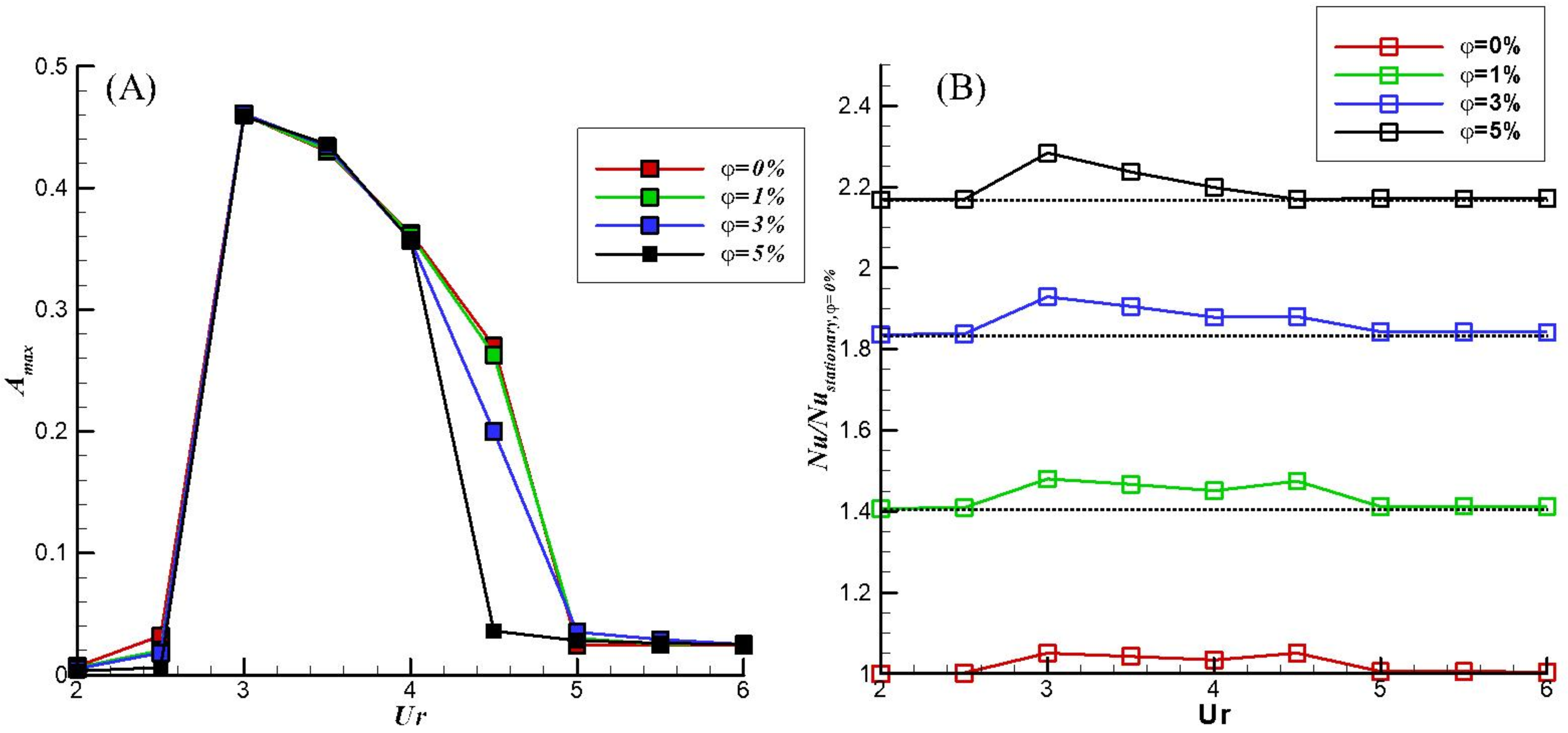
Figure 5A shows the relationship between U r and A max for different φ s, while Figure 5B shows the relationship between U r and N u / N u s t a t i o n a r y , φ = 0 % for different φ s. Figure 5A also presents that the increase in the concentration reduces the Lock-in range. However, Figure 5B shows that concentration increase in N u / N u s t a t i o n a r y , φ = 0 % and amplitude has a positive correlation with N u / N u s t a t i o n a r y , φ = 0 % . The decrease in the Lock-in range means that under the same U r condition, the increase in φ makes the cylinder change from large A max to small A max , as indicated by U r = 4 . 5 . Small amplitude is unfavorable for heat transfer, as indicated by U r = 4 . 5 in Figure 5B.

4. Conclusions

By using nanoparticle transport equations and considering the Brownian motion and thermophoresis of the particles, an immersed boundary method is used to simulate the elastically mounted cylinder moving inside the nanofluid-filled microchannel. The good thermal conductivity of solids is combined with the convective properties of fluids to improve overall heat transfer efficiency. In combination with the vortex-induced vibration of the cylinder, the heat transfer efficiency is improved again. The main results in this study with bullet points are presented as follows.
(1)
In the Lock-in range, the heat transfer efficiency can be improved. For example, when U r = 3 and φ = 0 % , the heat transfer efficiency is increased by about 5.08% compared to the fixed cylinder case.
(2)
Increasing the concentration reduces the Lock-in range.
(3)
Increasing the concentration results in heat transfer enhancement. When U r = 3 , φ increases from 0 to 5%, and the heat transfer efficiency increases by 117.3%.

Author Contributions

Y.-B.L.: Validation, Investigation, Data curation, Writing—original draft preparation, Visualization; C.-C.L.: Conceptualization, Methodology, Formal analysis, Investigation, Resources, Writing—original draft preparation, Writing—review and editing, Supervision, Project administration, Funding acquisition. All authors have read and agreed to the published version of the manuscript.

Funding

This research was funded by the Ministry of Science and Technology (NSTC 112-2221-E-033-026, MOST 111-2221-E-033-031).

Institutional Review Board Statement

Not applicable.

Informed Consent Statement

Not applicable.

Data Availability Statement

Not applicable.

Acknowledgments

This research was funded by the Ministry of Science and Technology, Taiwan, ROC via Grant No. MOST 111–2221-E-033–031.

Conflicts of Interest

The authors declare no conflict of interest.

References

  1. Ju, W.J.; Fu, L.M.; Yang, R.J.; Lee, C.L. Distillation and detection of SO2 using a microfluidic chip. Lab. Chip. 2012, 12, 622–626. [Google Scholar] [CrossRef] [PubMed]
  2. Tuckerman, D.B.; Pease, R.F.W. High-performance heat sinking for VLSI. Electron Device Lett. 1981, 2, 126–129. [Google Scholar] [CrossRef]
  3. Yeom, T.; Simon, T.W.; Yu, Y.; North, M.T.; Cui, T. Convective heat transfer enhancement on a channel wall with a high frequency, oscillating agitator. In Proceedings of the ASME International Mechanical Engineering Congress and Exposition, Denver, CO, USA, 11–17 November 2011; pp. 875–884. [Google Scholar]
  4. Celik, B.; Raisee, M.; Beskok, A. Heat transfer enhancement in a slot channel via a transversely oscillating adiabatic circular cylinder. Int. J. Heat Mass Transf. 2010, 53, 626–634. [Google Scholar] [CrossRef]
  5. Kumar, V.; Garg, H.; Sharma, G.; Bhardwaj, R. Harnessing flow-induced vibration of a D-section cylinder for convective heat transfer augmentation in laminar channel flow. Phys. Fluids 2020, 32, 19. [Google Scholar] [CrossRef]
  6. Lienhard, J.H. Synopsis of Lift, Drag, and Vortex Frequency Data for Rigid Circular Cylinders; Technical Extension Service; Washington State University: Pullman, WA, USA, 1966; Volume 300. [Google Scholar]
  7. Zhao, M.; Cheng, L.; An, H.; Lu, L. Three-dimensional numerical simulation of vortex-induced vibration of an elastically mounted rigid circular cylinder in steady current. J. Fluids Struct. 2014, 50, 292–311. [Google Scholar] [CrossRef]
  8. Buongiorno, J. Convective transport in nanofluids. J. Heat Transf.-Trans. ASME 2006, 128, 240–250. [Google Scholar] [CrossRef]
  9. Liao, C.C. Heat transfer transitions of natural convection flows in a differentially heated square enclosure filled with nanofluids. Int. J. Heat Mass Transf. 2017, 115, 625–634. [Google Scholar] [CrossRef]
  10. Liao, C.-C.; Chang, Y.-W.; Lin, C.-A.; McDonough, J. Simulating flows with moving rigid boundary using immersed-boundary method. Comput. Fluids 2010, 39, 152–167. [Google Scholar] [CrossRef]
  11. Corcione, M. Empirical correlating equations for predicting the effective thermal conductivity and dynamic viscosity of nanofluids. Energy Conv. Manag. 2011, 52, 789–793. [Google Scholar] [CrossRef]
  12. Meis, M.; Varas, F.; Velazquez, A.; Vega, J.M. Heat transfer enhancement in micro-channels caused by vortex promoters. Int. J. Heat Mass Transf. 2010, 53, 29–40. [Google Scholar] [CrossRef] [Green Version]
  13. Soti, A.K.; De, A. Vortex-induced vibrations of a confined circular cylinder for efficient flow power extraction. Phys. Fluids 2020, 32, 16. [Google Scholar] [CrossRef]
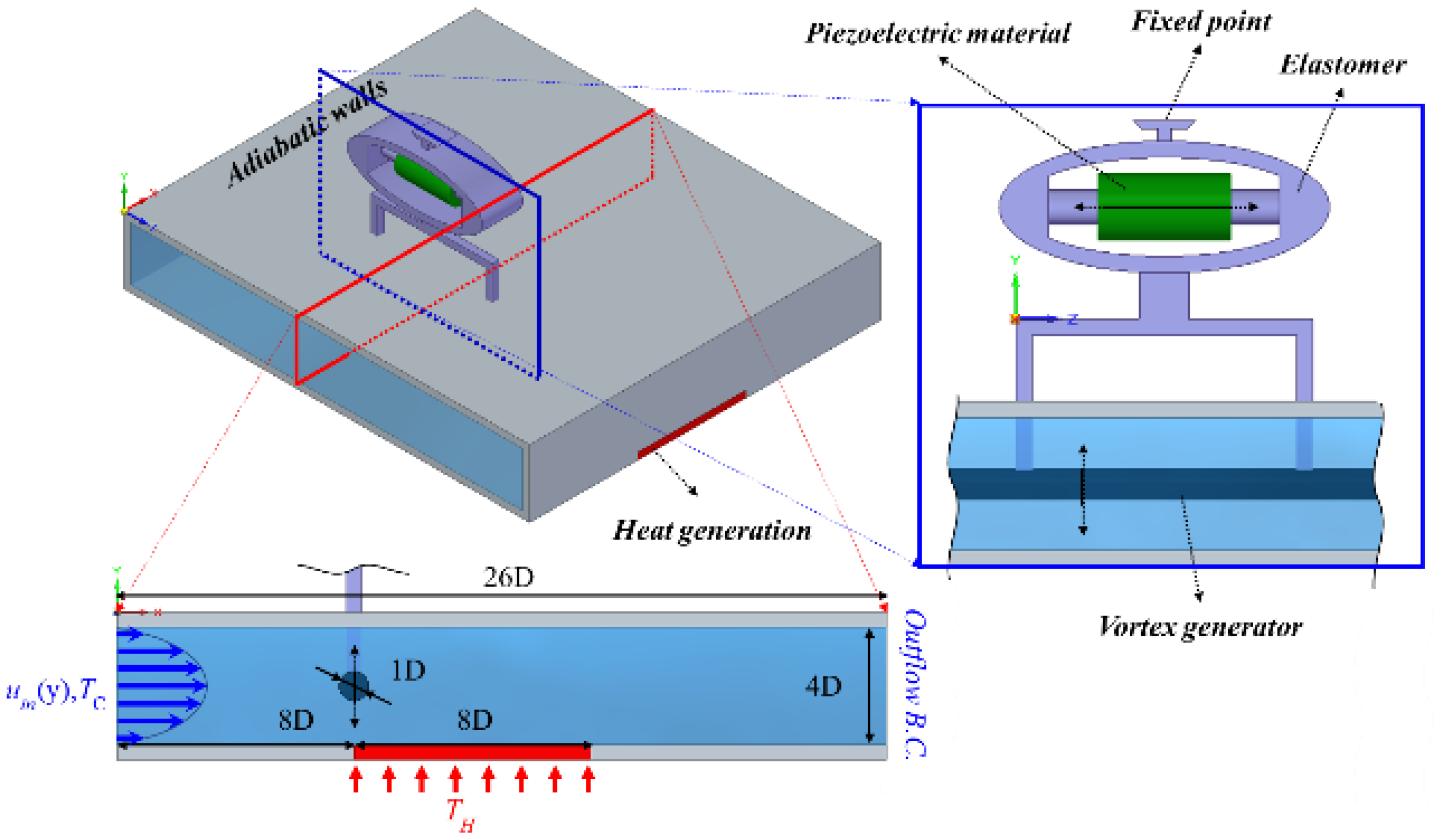
Figure 1. Schemes follow the same formatting.
Engproc 38 00068 g001
Figure 2. (A) Compared with the data in Soti [13], the Strouhal number ( S t ) with the stationary circular cylinder of diameter ( D ) kept inside a channel of height ( H ) at Re = 100 . (B) compared with the data in Kumar [5], A max with U r at Re = 100 .
Engproc 38 00068 g002
Figure 3. Mesh independence study for Ur = 4. Effect of elements on (A) maximum amplitude A max and (B) frequency ratio f v / f n .
Engproc 38 00068 g003
Figure 4. (A) mean position (moving upward), (B) upper extreme, (C) mean position (moving downward), and (D) lower extreme positions of the cylinder vorticity plot and isotherm plot. The legend “vorticity” is used for the upper plot, and the legend “T” is used for the lower plot.
Engproc 38 00068 g004
Figure 5. (A) the A max curve of different U r and φ . (B) the N u / N u s t a t i o n a r y curve of different φ s.
Engproc 38 00068 g005
Disclaimer/Publisher’s Note: The statements, opinions and data contained in all publications are solely those of the individual author(s) and contributor(s) and not of MDPI and/or the editor(s). MDPI and/or the editor(s) disclaim responsibility for any injury to people or property resulting from any ideas, methods, instructions or products referred to in the content.