Abstract
Power generation dependency on natural gas in Uzbekistan is high, with more than 85% of the country’s electricity production coming from natural gas. Hence, natural gas-fired power plants constitute the largest proportion of the country’s greenhouse gas emissions. Carbon capture, storage, and utilization (CCSU) play an essential role in reaching Uzbekistan’s reduction targets for carbon dioxide (CO2) emissions. In this study, one (450 MW) of the two identical blocks of a 900 MW Turakurgan natural gas-fired combined cycle power plant (NGCCPP), located in the Fergana valley in Uzbekistan, is simulated using Aspen Plus® commercial software and is validated with its open access project data prior to the evaluation of end-of-pipe CCSU unit integration. An optimal value of exhaust gas recirculation (EGR) is identified in order to further increase the CO2 content in the flue gas while reducing the flue gas flow rate. In addition, according to the simulation results, more than 2.16 Mt of annual CO2 emissions can be avoided when the capture plant is set at a 90% CO2 capture rate. Apart from that, the suitability of various CCSU integration methods such as absorption, adsorption, membrane separation, and CO2 bio-fixation is discussed, considering the power plant’s site-specific conditions and the obtained flue gas stream characteristics.
1. Introduction
Global climate change has become a major issue for the entire world in the 21st century. An increased amount of carbon dioxide (CO2) in the atmosphere is considered to be the primary leading factor of global warming. The fossil fuel-dependent energy sector, principally driven by coal and natural gas (NG), is one of the main sources responsible for more than a third of the total global CO2 emissions []. In this context, to meet the target of the Paris Agreement (2015) of limiting the temperature rise far below 2 °C, preferably 1.5 °C, above the pre-industrial level, the decarbonization of the fossil fuel-based electricity generation in line with the other large industrial point sources ought to be the priority of each country’s policy.
The current state of power generation in the Republic of Uzbekistan (hereinafter referred to as Uzbekistan) is heavily dependent on thermal power plants (TPP) with more than 85% of the country’s electricity coming from TPPs, mainly running on NG []. Uzbekistan’s first target towards net zero emissions is to cut its greenhouse gas emissions by 35% by the end of 2020s. In this way, the country’s main green economy policy includes the transition to solar, wind, and hydrogen energy, reaching a minimum of 25% share of renewables by 2025 []. Although the transition from fossil fuel-based power sources to renewable energy is seen as the most feasible climate change mitigation strategy, it is uncertain, especially in the current growing urbanization and population situation, to meet the energy demand of the whole country using renewables as far as the period from now to 2050 is concerned. Therefore, the implementation and feasibility of other decarbonization alternatives such as carbon capture, storage, and utilization (CCSU) in Uzbekistan’s condition should be thoroughly evaluated.
For the reliable assessment of CCSU integration possibilities in Uzbekistan, there is a necessity to develop a rigorous CCSU model to evaluate techno-economic, site-specific conditions with different scenarios. From this perspective, initially, a simulation with an exhaust gas recirculation (EGR) analysis of one block of two identical 450 MW Turakurgan natural gas-fired combined cycle power plants (NGCCPPs) was selected as an object of this investigation, due to the following reasons:
- NG is the abundant and primary fuel for energy production in Uzbekistan;
- NG has cleaner emissions compared to coal, oil, and other heavier hydrocarbons;
- The majority of the TPPs operate in the combined cycle principle in Uzbekistan;
- NGCCPPs are not likely to be replaced by renewables in the near term.
Although NGCCPPs have relatively low CO2 emission factors compared to coal-fired power plants (CFPP), at 364 and 800 kgCO2/MWh, respectively [], the CO2 concentration in the NGCCPPs (4.0 vol%) and flue gas is much less than those of the CFPP (15 vol%) counterparts, which makes capture unfeasible. Thus, recycling a part of the exiting flue gas as EGR in a combined cycle process has a significant impact on the CCSU process intensification. There are several research papers [,], which developed the NGCCPP model prior to CCSU integration and analyzed EGR integration for different types of gas turbines. However, the effect of EGR with different ratios on various parameters and the location of the plant is rarely considered. In this paper, a simulation of one block of Turakurgan TPP is developed and validated with the plant’s preparatory project report data. Apart from that, the EGR effect on the power plant’s performance and other main parameters is studied and discussed. Moreover, there is a brief discussion about the integration of different post-combustion CO2 capture methods and their feasibility in the case of Turakurgan NGCCPP.
2. Model Development
2.1. Brief Process Description in the Base Case
The Turakurgan TPP consists of two of the same (450 MW outputs) blocks with Mitsubishi Hitachi M701F Series gas turbines (GT). The simulation of one block of the 450 MW gas and steam turbine was developed and validated using the commercial software Aspen Plus® (AspenTech, Bedford, MA, USA) (See Figure 1). In the power generation process, 664.5 kg/s of ambient air with a pressure of 0.944 bar was compressed up to 18 bar and was divided into two directions—one for the combustion reactor after mixing with 16.11 kg/s (lower calorific value (LCV)—46.750 kJ/kg) of natural gas, while another one was used to cool down the hot flue gas coming out of the combustion chamber right after the heating of the natural gas by the heat exchanger. Due to the metallurgical limitation on the inlet temperature of up to 1300 °C of the F-type GTs, an extra amount of air of 34 kg/s was used to keep the GT inlet temperature at a permissible level (the exact amount of cooling air is not provided in the project report, so it is calculated by Aspen Plus in response to the GT inlet temperature limitations). The GT outlet hot gas at 1 bar and 596 °C was fed to the heat recovery steam generator (HRSG) where the heat from the hot flue gas was absorbed by the heat exchangers, generating even more power with three steam streams in high pressure at 127 bar, intermediate pressure at 27.5 bar, and low-pressure steam turbines (ST) at 4.5 bar. The flue gas exits the HRSG (14) at 104 °C and 0.981 bar.
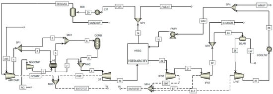
Figure 1.
Simulation flowsheet of Turakurgan natural gas-fired combined cycle power plant with exhaust gas recirculation.
2.2. EGR Integration Process
The exhaust gas (mainly nitrogen (N2), oxygen (O2), CO2, and water vapor (H2O)) exiting the power plant was split into two streams (FGEXIT and FGR) in the optimal ratio; one goes to the CO2 capture plant while the other one is recirculated back to the compressor after removing part of the H2O content from the flue gas by directly cooling with cold water down to an average 10–20 °C (see in Figure 1). The additional amount of water required to cool the recirculated stream was supplied by Grand Canal Namangan, an artificial irrigation channel composed of concrete with an average water flowrate of 6.6 m3/s []. The EGR effect on the additional water demand for the CO2 capture process was very small due to the EGR advantage of the flue gas flowrate decrease. Even if EGR was not applied, flue gas needs to be cooled down for most CO2 capture techniques, including absorption, adsorption, and membrane separation. Cooled and partly dehydrated flue gas was mixed with ambient air reducing its flowrate coming into the compressor. The exact ambient air flowrate reduction was calculated in only the condition of the GT inlet temperature (stream 9) at 179–180 °C in all different EGR ratio cases, except for the EGR ratio at 0.6 because the EGR ratio at this point creates massive O2 deficiency leading to simulation errors.
3. Results and Discussion
3.1. Simulation Results and Validation
The summary of the comparison of project data and simulation results is given in Table 1. It is apparent from the table, in most cases, there is a good agreement between the simulation results and the power plant’s project report data []. However, since the focus of this investigation is mainly on the flue gas flowrate and characteristics before the design of the CO2 capture plant, the auxiliary power consumption of the plant is estimated as 3% of its net power output (this includes the pumps, compressors, water treatment plant, etc.). While calculating the annual CO2 emissions, the capacity factor was obtained from the project report as 86.8%. According to the CO2 emission result, at least more than 2.16 Mt of CO2 can be avoided when the capture rate is at 90% standard.

Table 1.
1 Unit gas turbine modeling tuning parameters and Aspen Plus simulation results.
3.2. The Effect of EGR on the Plant’s Performance and Different Parameters
EGR is considered a feasible approach to avoid the huge energy penalty of CO2 capture plants due to the relatively low concentration of CO2 and the high amount of flue gas flowrate which makes CO2 separation costly. EGR can easily be integrated without making a significant change to the existing plant. For instance, using EGR integration, in the case of CO2 capture with the absorption method, it is possible to reduce the flue gas flowrate to enable the capital cost reduction in response to using smaller dimensions of the absorber and stripper towers. The increased CO2 content, on the one side, provides a better mass transfer rate, which results in a lower solvent pumping requirement. On the other side, the risks of oxidative degradation in the presence of O2 can also be reduced with decreased O2 content in the flue gas, since O2 is usually regarded as an impurity in the CO2 capture process. Figure 2 indicates the effect of EGR ratios from 0 to 0.6 with a 0.05 step on the molar concentration of O2, CO2, and combustor outlet O2, as well as the exiting flue gas mass flowrate.
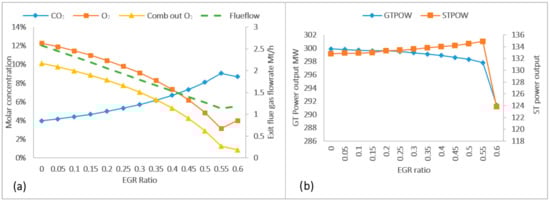
Figure 2.
The effect of exhaust gas recirculation in different ratios on the exiting flue gas mass flowrate and the molar concentration of different compounds (a). The effect of exhaust gas recirculation on the power output of the gas turbine and steam turbines (b).
It can be observed from Figure 2a that, at first glance, nearly all variables are reaching their optimal value when the EGR ratio is 0.55. After this point, the amount of ambient air cannot be reduced, even though the amount of recirculated flue gas increases due to O2 deficiency in the combustor and a significant quantity of carbon monoxide (CO) generation. However, for the combustion reaction to occur stable and for the conversion of all hydrocarbons completely, O2 content in the combustor outlet flue gas should be between 3 and 4 mol%. In terms of the EGR effects on the GT and ST power outputs, the result shows that as the EGR ratio is increased, the GT power output is decreasing, while the ST power output generates more power (see Figure 2b). The GT power generation efficiency decrease can be explained by the fact that the flowrate of the air and gas mixture coming into the compressor is slightly higher than without the EGR case so as to keep the GT inlet temperature at 179–180 °C in each EGR ratio test, resulting in the compressor’s higher power consumption. For instance, the flowrate of the compressor inlet mixture gas is higher by approximately 1.15 kg/s at the 0.05 EGR ratio and by 10.1 kg/s at the 0.5 EGR ratio than the value without EGR. In the case of a positive effect of EGR on steam turbines, as the EGR ratio increases, the GT outlet temperature also increases, resulting in more steam generation and as the power output increases. The steam cycle power output at 0.45 of the EGR ratio generates 1.05% more electricity than that without EGR.
Regarding the above-mentioned conditions, the EGR ratio at 0.45 is selected as an optimal case for this process in order to keep the flame stable in the combustor. Above this EGR ratio, there is less than 3 mol% O2 at the combustor outlet that can negatively impact the burner and combustion process. In this selected optimal case, the CO2 content in the flue gas can be increased from 3.96 mol% to 7.32 mol%, while the O2 concentration reduces from 12.28 mol% to 6.2 mol%. The flue gas mass flowrate leaving the power plant decreases by 45.8%, equivalent to roughly 389 kg/s. Although the power output of GT reduces by 1.3 MW, it is compensated by the additional power generation of ST by 1.4 MW, compared to the non-EGR case. Overall, the EGR integration can be implemented prior to the CO2 capture plant integration without deteriorating the plant’s performance.
3.3. Suitability of Different CO2 Capture Techniques in the Case of Turakurgan TPP
When it comes to evaluating the suitability of different CO2 capture technologies for Turakurgan TPP, the site-specific conditions and resource availability factors of the power plant are the most essential part of the research. Another important factor that must be considered is the characterization of the flue gas which will further be treated in a CO2 capture plant (See in Table 2).
Table 2.
Flue gas stream characteristics leaving the power plant.
Since the concentration of CO2 in the flue gas is directly proportional to the capture cost [], the CO2 concentration of Turakurgan TPP’s flue gas (7.3 mol%) after implementing 0.45 EGR ratio still remains too low to integrate the adsorption method cost effectively, while the flowrate of flue gas is also still high for successful membrane separation application. The CO2 bio-fixation method, on the one hand, can be seen as the most feasible option for the flue gases, even with very low CO2 contents without the need for flue gas pre-treatment and captured CO2 storage issue. On the other hand, this technique requires a huge amount of water or wastewater resources, which are nearly impossible to find around the plant location. Apart from that, CO2 bio-fixation has not reached its maturity level and the installation cost of a large number of photobioreactors is also problematic [,]. In this context, the only option that can be implemented is conventional chemical absorption technology with an appropriate solvent. Membrane separation is also applicable in the hybrid form with chemical absorption by partially removing CO2 from the flue gas, resulting in an increase in the concentration of CO2 and a flue gas flowrate decrease, as well as the reduction of huge absorption and stripper columns dimensions. However, both applicable approaches need to be thoroughly studied in all aspects, including techno–economic and life cycle analysis based on site-specific conditions and available resources.
4. Conclusions
The simulation of one block of the 450 MW gas and steam turbine was developed and validated using the commercial software Aspen Plus®. According to the results, there is a good agreement between the simulation results and the power plant’s project report data. An EGR ratio of 0.45 is selected as an optimal case and analyzed its effect on different parameters. Overall, based on the plant’s location and resource existence, absorption with an appropriate solvent and hybrid membrane–absorption approaches are recommended to further study the possible integration and their techno–economic and life cycle analysis.
Author Contributions
Conceptualization, A.N. and A.K.; methodology, M.V., M.F. and A.K.; software, A.K. and Z.T.; writing—original draft preparation, A.K. and Z.T.; writing—review and editing, A.K.; visualization, A.K. and Z.T.; supervision, M.V., A.N. and M.F.; A.K. and Z.T. contributed equally to this paper. All authors have read and agreed to the published version of the manuscript.
Funding
This research was funded by the Slovak Research and Development Agency, grant number APVV-18-0134 and APVV-19-0170.
Institutional Review Board Statement
Not applicable.
Informed Consent Statement
Not applicable.
Data Availability Statement
The data presented in this study are available on request from the corresponding author.
Acknowledgments
The first author acknowledges the national scholarship program of the Slovak Republic for making an opportunity to carry out this study in Slovakia under the international collaboration.
Conflicts of Interest
The authors declare no conflict of interest.
References
- Gür, T.M. Carbon Dioxide Emissions, Capture, Storage and Utilization: Review of Materials, Processes and Technologies. Prog. Energy Combust. Sci. 2022, 89, 100965. [Google Scholar] [CrossRef]
- Japan International Cooperation Agency (JICA). Preparatory Survey on Turakurgan Thermal Power Station Construction Project; Tokyo Electric Power Services Co., Ltd.: Namangan, Uzbekistan, 2014; Available online: https://openjicareport.jica.go.jp/pdf/12175436.pdf (accessed on 6 May 2023).
- Bne IntelliNews—Uzbekistan Tells COP26 It Aims to Cut Emissions by 35% within Decade. Available online: https://shorturl.at/rxIQ9 (accessed on 6 May 2023).
- Hu, Y.; Ahn, H. Process Integration of a Calcium-Looping Process with a Natural Gas Combined Cycle Power Plant for CO2 Capture and Its Improvement by Exhaust Gas Recirculation. Appl. Energy 2017, 187, 480–488. [Google Scholar] [CrossRef]
- Luo, X.; Wang, M.; Chen, J. Heat Integration of Natural Gas Combined Cycle Power Plant Integrated with Post-Combustion CO2 Capture and Compression. Fuel 2015, 151, 110–117. [Google Scholar] [CrossRef]
- Dillon, D.; Grace, D.; Maxson, A.; Børter, K.; Augeli, J.; Woodhouse, S.; Aspelund, G. Post-Combustion Capture on Natural Gas Combined Cycle Plants: A Technical and Economical Evaluation of Retrofit, New Build, and the Application of Exhaust Gas Recycle. Energy Procedia 2013, 37, 2397–2405. [Google Scholar] [CrossRef]
- Srivastav, P.; Schenkel, M.; Mir, G.R.; Berg, T.; Staats, M. Carbon Capture, Utilisation and Storage, (CCUS): Decarbonisation Pathways for Singapore’s Energy and Chemicals Sectors; Navigant: Utrecht, The Netherlands, 2021; Available online: https://shorturl.at/ouAQT (accessed on 6 May 2023).
- Kamolov, A.; Turakulov, Z.; Rejabov, S.; Díaz-Sainz, G.; Gómez-Coma, L.; Norkobilov, A.; Fallanza, M.; Irabien, A. Decarbonization of Power and Industrial Sectors: The Role of Membrane Processes. Membranes 2023, 13, 130. [Google Scholar] [CrossRef] [PubMed]
Disclaimer/Publisher’s Note: The statements, opinions and data contained in all publications are solely those of the individual author(s) and contributor(s) and not of MDPI and/or the editor(s). MDPI and/or the editor(s) disclaim responsibility for any injury to people or property resulting from any ideas, methods, instructions or products referred to in the content. |
© 2023 by the authors. Licensee MDPI, Basel, Switzerland. This article is an open access article distributed under the terms and conditions of the Creative Commons Attribution (CC BY) license (https://creativecommons.org/licenses/by/4.0/).