Abstract
Three-dimensional multiphoton laser lithography of hybrid resins has been shown to be a viable tool for producing micro-optical functional components. The use of calcination heat treatment also allows the transformation of such structures from the initial polymer to final glass and glass-ceramic. Although the laser-induced damage threshold (LIDT) is an important parameter in characterizing all optics, it was not known for such sol–gel-derived glass microstructures. Here we present the first pilot study regarding this parameter, wherein functional microlenses have been made, damaged and calcinated for the series-on-one protocol. The results point to the fact that the LIDT can be increased significantly, even multiple times, thus expanding the usability of such resilient micro-optics.
1. Introduction
The field of laser multi-photon lithography is rapidly progressing. More and more interesting micro-optical devices are given form at the micro-scale. Examples include conventional [1] and Fresnel micro-lenses [2], holographic elements [3], meta-optics [4,5] multi-component systems [6], and most notably, micro objectives [7]. One problem overlooked with such systems is the laser-induced damage threshold (LIDT) behavior. The major limitations stem from the fact that ease of manufacturing does not guarantee a high LIDT. Arguably not all applications are demanding in this regard [8], yet the domain of modern high-intensity pico- and femto-second pulses might be barred.
Some attempts to measure LIDT have been made and show variation depending on the following: if the resin used is organic or hybrid [9,10,11]; if a photo-initiator (PI) is used [12]; if the structure is a thin-film [11], bulk object [13] or a device [14,15]. Technically, the way to increase LIDT is by choosing resins without PI [16] and a less organic composition [17]. We want to go beyond this concept by using an alternative approach: making purely inorganic structures using a heat-based post-processing method called calcination, without disregarding the convenient multiphoton 3D printing method [18].
Essentially, for metal–organic systems such as SZ2080TM [19] above 1000 °C [20], the resulting phase is an inorganic composite glass or glass-ceramic phase while retaining the printed geometry with homogeneous and repeatable shrinking [21]. Intuition dictates that transparent glassy [22] structures should feature higher LIDT values and, therefore, must be more resilient to high-intensity radiation, but this idea was never tested [14].
Therefore, the goal of this paper is to fabricate suspended and functional structures, Figure 1a, in this case, microlenses, heat-treat them, Figure 1b, and confirm the useful increase in LIDT, Figure 1c.
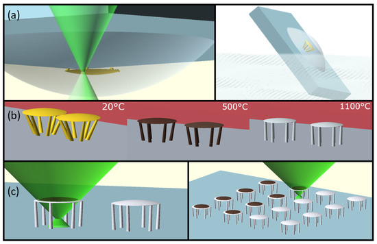
Figure 1.
The experimental principle: (a) the fabrication of the test lens structure in resin, (b) heat treatment of the structure and compliant columns, (c) the exposure of the structures to measure the LIDT values.
2. Methods
To produce the lenses, we used the low-shrinkage organic–inorganic prepolymer SZ2080TM. The preparation and exposure and conditions (Figure 1a) were selected similarly to Ref. [23] using a 1.4 NA objective, 517 ± 10 nm wavelength and 144 fs pulse duration and a repetition rate of 76 MHz. The lenses were printed on a quartz substrate. The final baseline geometry was of a plano-convex, 50 μm diameter, 300 μm focal length lens, with a thickness of approximately 2 μm. To support the lenses above the quartz substrate, pillars were printed with an inclination angle of 35° and a total height close to 30 μm. Heat treatment was performed at 1100 °C with a rise time of 12 h and held for 3 h. Some reactions with the ambient atmosphere are expected; however, the final transparent phase generated at the highest treatment temperature is of the essence here (Figure 1b). Non-calcinated (NCA) and calcinated (CA) samples were qualitatively examined and exposed to the probe beam in damage tests in an array form. (Figure 1c). Qualitative characterization of their imaging function was performed in a bright-field microscope to confirm their imaging function before and after LIDT measurements. See Figure 2a–d for the illustrated concept. The imaging function was used to confirm the occurrence of significant and catastrophic damage events (Figure 2b–d). After, they were characterized using a scanning electron microscope (SEM) and provided in Figure 3.
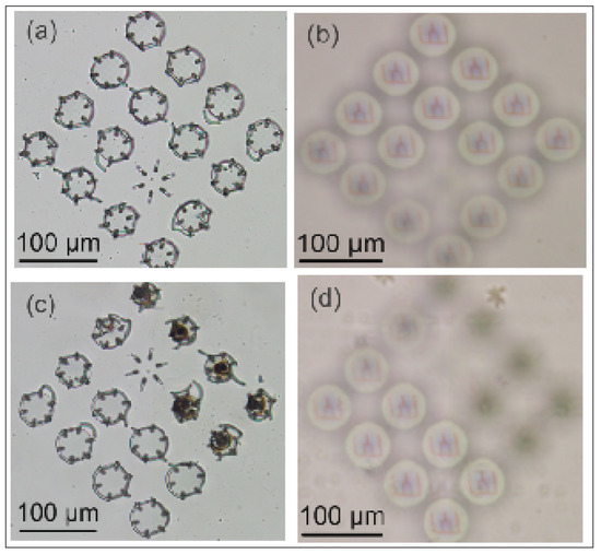
Figure 2.
Optical characterization of micro-optics using an inverted microscope: (a) image of the surface of the optic components, (b) an image of the focal position (300 μm) of the same micro-optics, (c) bright-field image after damage, (d) degradation in image quality in the focal position of damaged lenses.
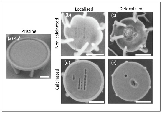
Figure 3.
Scanning electron microscope micrographs of micro-lenses, illustrating the typical damage morphologies observed. The scale bar is 10 μm: (a) image of an NCA lens without damage, (b) local damage protocol lens damaged before CA, (c) delocalized damage protocol lens damaged before CA, (d) local protocol lens damaged after CA, (e) delocalized protocol lens damaged after CA. Tracks are formed for easier visualization of the damaged sites.
Damage tests were performed on arrays of micro-lenses. Arrays, mainly composed of 16 lenses, were divided in half to account for damage experiments for NCA (control) and CA (test) micro-optics. Damage tests were performed in the following sequence: an array of lenses is printed, half of the lenses are damaged before calcination, then the array is calcinated as described previously, and finally, the second half of the lenses are damaged. The laser system parameters used for all experiments were as follows: wavelength nm and = 515 nm, repetition rate f = 200 kHz, pulse duration = 300 fs, Plan-Apochromat Zeiss 20× objective (0.8 NA). S-on-1 damage tests were performed with both wavelengths, exposing the lenses for 50 ms and 5 s, corresponding to 10,000-on-1 and 1,000,000-on-1 pulses.
In addition, two damage protocols were tested. The first protocol is referred to as a local-damage protocol, where the beam diameter is approximately 4 μm ( intensity level) on the sample. The second protocol is the delocalized-damage protocol, where the probe beam is 20 μm. The reasoning behind the delocalized damage protocol is to demonstrate the expected behavior where the full aperture of the lens is used.
3. Results
3.1. Morphology
The observed damage morphology is shown in Figure 3. For comparison, an example of a pristine lens is given in Figure 3a. Such a lens initially is of 50 μm in diameter and, after calcination, shrinks down to 30 μm. The localized damage protocol produces small damage sites. The delocalized-damage protocol produces large damage sites for NCA lenses (Figure 3b). In this case, the lenses lose their imaging function as most of the aperture becomes distorted. The damage is technically catastrophic. On the other hand, the CA lenses shown in Figure 3d,e retain their qualitative imaging function and feature small diameter ablation sites reminiscent of fs-laser surface ablation. The morphology does not differ in any meaningful manner independent of the wavelength used. The only observed difference for NCA lenses is that brown discoloration is prominent, especially for nm.
3.2. LIDT Values
The measurement results of LIDT values are summarized in Figure 4. We analyzed a combination of cases of localized and nonlocalized damage protocols, NCA and CA, -on-1 and -on-1, and 515 and 1030 nm wavelengths. The NCA localized damage results correspond well in the margin of error with the ones presented in the literature: J/cm and J/cm.
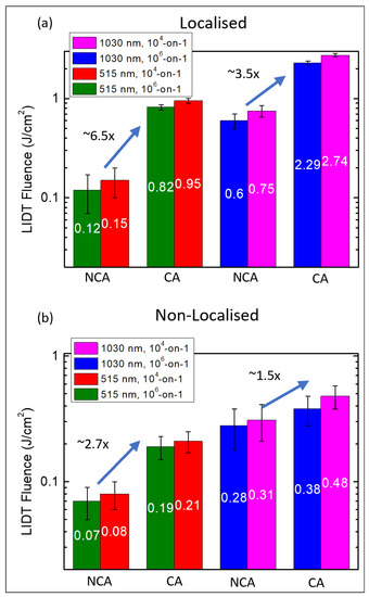
Figure 4.
Light induced damage threshold measurement results for (a) localized damage protocol, (b) non-localized damage protocol.
The non-localized damage thresholds do not correspond as accurately to previous results. They are lower. However, it is essential to note that the previously known experiment in which S-on-1 damage testing protocols were employed used only up to 1000 pulse exposure, so the current results with decreased LIDT are novel.
Damage thresholds of calcinated micro-optics from locally induced damage showed the highest increase—for 1030 nm damaging wavelength, a 3-fold increase was observed from F = 0.6–0.8 J/cm to F = 2.3–2.7 J/cm, using a 300 fs laser pulse duration. This damage threshold was the highest out of all measured values and contained the entire exposure duration range from 50 ms to 5 s. The highest percentile increase in resilience was observed from using a second harmonic (515 nm)—around a 6-fold increase from uncalcinated micro-optics damage tests in all exposure durations from F = 0.12–0.17 J/cm to F = 0.8–0.9 J/cm.
A decrease in damage thresholds is also observed when the laser focus position is shifted, thus increasing the exposure area on the lens compared to uncalcinated counterparts. For the 1030 nm wavelength, the most minor calcination influence was measured—damage thresholds increased only approximately 0.5 times from F = 0.28–0.31 J/cm for uncalcinated micro-optics to F = 0.38–0.47 J/cm for calcinated lenses.
The main result observable for all cases is that the LIDT values always increase CA microlenses. The results are consistent, independent of irradiation area, testing process, etc.
4. Conclusions
Optical damage threshold measurements of SZ2080 material after calcination have been reported for the first time. The structures have been processed at a temperature of 1100 °C and feature a significant increase in damage threshold, reaching 300–600% as a conservative estimate. This increase supersedes all previously measured values [11,12,17]. In addition, the maximum measured LIDT value at = 1030 nm is F = 2.74 J/cm. It is relatively large as it approaches the level of fused silica [13] F = 3.11 J/cm. This result is promising, as applications of this material in harsh environments, as postulated many times previously, are proven for optical and IR wavelengths. Thus, the multiphoton lithography method combined with heat treatment can offer a technologically viable pathway to producing optical-grade, glass-level performance micro-optical elements.
Finally, as this is a pilot study, more research should be carried out for other significant regimes, such as nanosecond and continuous-wave damage tests. Regardless, the current results give credibility to the hypothesis that further research will also feature increased LIDT values.
Author Contributions
Conceptualization, D.G. and M.M.; methodology, D.G. and R.Z.; software, R.Z.; validation, R.Z., D.G. and M.M.; formal analysis, D.G.; investigation, R.Z.; resources, M.M.; data curation, D.G.; writing—original draft preparation, D.G.; writing—review and editing, M.M.; visualization, R.Z.; supervision, D.G.; project administration, M.M.; funding acquisition, M.M. All authors have read and agreed to the published version of the manuscript.
Funding
This research received funding from EU Horizon 2020, Research and Innovation program LASERLAB-EUROPE JRA Project No. 871124.
Institutional Review Board Statement
Not applicable.
Informed Consent Statement
Not applicable.
Data Availability Statement
Data available on request from the authors.
Acknowledgments
We acknowledge Maria Farsari and Vasileia Melissinaki for kindly providing the authors with the SZ2080TM (IESL-FORTH, Heraklion, Greece) hybrid organic–inorganic materials for performing the described experiments.
Conflicts of Interest
The authors declare no conflict of interest.
References
- Wu, D.; Chen, Q.D.; Niu, L.G.; Jiao, J.; Xia, H.; Song, J.F.; Sun, H.B. 100% Fill-Factor Aspheric Microlens Arrays (AMLA) With Sub-20-nm Precision. IEEE Photonics Technol. Lett. 2009, 21, 1535–1537. [Google Scholar] [CrossRef]
- Asadollahbaik, A.; Thiele, S.; Weber, K.; Kumar, A.; Drozella, J.; Sterl, F.; Herkommer, A.M.; Giessen, H.; Fick, J. Highly Efficient Dual-Fiber Optical Trapping with 3D Printed Diffractive Fresnel Lenses. ACS Photonics 2020, 7, 88–97. [Google Scholar] [CrossRef]
- Sandford O’Neill, J.; Salter, P.; Zhao, Z.; Chen, B.; Daginawalla, H.; Booth, M.J.; Elston, S.J.; Morris, S.M. 3D Switchable Diffractive Optical Elements Fabricated with Two-Photon Polymerization. Adv. Opt. Mater. 2022, 10, 2102446. [Google Scholar] [CrossRef]
- Faniayeu, I.; Mizeikis, V. Realization of a helix-based perfect absorber for IR spectral range using the direct laser write technique. Opt. Mater. Express 2017, 7, 1453. [Google Scholar] [CrossRef]
- Faniayeu, I.; Khakhomov, S.; Semchenko, I.; Mizeikis, V. Highly transparent twist polarizer metasurface. Appl. Phys. Lett. 2017, 111, 1–5. [Google Scholar] [CrossRef]
- Žukauskas, A.; Malinauskas, M.; Brasselet, E. Monolithic generators of pseudo-nondiffracting optical vortex beams at the microscale. Appl. Phys. Lett. 2013, 103, 181122. [Google Scholar] [CrossRef]
- Thiele, S.; Arzenbacher, K.; Gissibl, T.; Giessen, H.; Herkommer, A.M. 3D-printed eagle eye: Compound microlens system for foveated imaging. Sci. Adv. 2017, 3, 2. [Google Scholar] [CrossRef]
- Sugioka, K.; Cheng, Y. Ultrafast lasers-reliable tools for advanced materials processing. Light. Sci. Appl. 2014, 3, 1–12. [Google Scholar] [CrossRef]
- Stankova, N.; Atanasov, P.; Nikov, R.; Nikov, R.; Nedyalkov, N.; Stoyanchov, T.; Fukata, N.; Kolev, K.; Valova, E.; Georgieva, J.; et al. Optical properties of polydimethylsiloxane (PDMS) during nanosecond laser processing. Appl. Surf. Sci. 2016, 374, 96–103. [Google Scholar] [CrossRef]
- Saha, S.K.; Divin, C.; Cuadra, J.A.; Panas, R.M. Effect of proximity of features on the damage threshold during submicron additive manufacturing via two-photon polymerization. J. Micro Nano-Manuf. 2017, 5, 031002. [Google Scholar] [CrossRef]
- Žukauskas, A.; Batavičiūtė, G.; Ščiuka, M.; Jukna, T.; Melninkaitis, A.; Malinauskas, M. Characterization of photopolymers used in laser 3D micro/nanolithography by means of laser-induced damage threshold (LIDT). Opt. Mater. Express 2014, 4, 1601. [Google Scholar] [CrossRef]
- Žukauskas, A.; Batavičiūtė, G.; Ščiuka, M.; Balevičius, Z.; Melninkaitis, A.; Malinauskas, M. Effect of the photoinitiator presence and exposure conditions on laser-induced damage threshold of ORMOSIL (SZ2080). Opt. Mater. 2015, 39, 224–231. [Google Scholar] [CrossRef]
- Gallais, L.; Commandré, M. Laser-induced damage thresholds of bulk and coating optical materials at 1030 nm, 500 fs. Appl. Opt. 2014, 53, A186. [Google Scholar] [CrossRef] [PubMed]
- Butkutė, A.; Čekanavičius, L.; Rimšelis, G.; Gailevičius, D.; Mizeikis, V.; Melninkaitis, A.; Baldacchini, T.; Jonušauskas, L.; Malinauskas, M. Optical damage thresholds of microstructures made by laser three-dimensional nanolithography. Opt. Lett. 2020, 45, 13–16. [Google Scholar] [CrossRef]
- Simakov, E.; Gilbertson, R.; Herman, M.; Pilania, G.; Shchegolkov, D.; Walker, E.; England, R.; Wootton, K. Possibilities for Fabricating Polymer Dielectric Laser Accelerator Structures with Additive Manufacturing. In Proceedings of the IPAC 2018, Vancouver, BC, Canada, 29 April–4 May 2018; pp. 9–12. [Google Scholar] [CrossRef]
- Samsonas, D.; Skliutas, E.; Ciburys, A.; Kontenis, L.; Gailevičius, D.; Berzinš, J.; Narbutis, D.; Jukna, V.; Vengris, M.; Juodkazis, S.; et al. 3D nanopolymerization and damage threshold dependence on laser wavelength and pulse duration. Nanophotonics 2023, 12, 1537–1548. [Google Scholar] [CrossRef]
- Kabouraki, E.; Melissinaki, V.; Yadav, A.; Melninkaitis, A.; Tourlouki, K.; Tachtsidis, T.; Kehagias, N.; Barmparis, G.D.; Papazoglou, D.G.; Rafailov, E.; et al. High laser induced damage threshold photoresists for nano-imprint and 3D multi-photon lithography. Nanophotonics 2021, 10, 3759–3768. [Google Scholar] [CrossRef]
- Merkininkaitė, G.; Aleksandravičius, E.; Malinauskas, M.; Gailevičius, D.; Šakirzanovas, S. Laser additive manufacturing of SiZrO2 tunable crystalline phase 3D nanostructures. Opto-Electr. Adv. 2022, 5, 210077. [Google Scholar] [CrossRef]
- Ovsianikov, A.; Viertl, J.; Chichkov, B.; Oubaha, M.; MacCraith, B.; Sakellari, I.; Giakoumaki, A.; Gray, D.; Vamvakaki, M.; Farsari, M.; et al. Ultra-Low Shrinkage Hybrid Photosensitive Material for Two-Photon Polymerization Microfabrication. ACS Nano 2008, 2, 2257–2262. [Google Scholar] [CrossRef]
- Gailevičius, D.; Padolskytė, V.; Mikoliūnaitė, L.; Šakirzanovas, S.; Juodkazis, S.; Malinauskas, M. Additive-manufacturing of 3D glass-ceramics down to nanoscale resolution. Nanoscale Horiz. 2019, 4, 647–651. [Google Scholar] [CrossRef]
- Gonzalez-Hernandez, D.; Varapnickas, S.; Merkininkaitė, G.; Čiburys, A.; Gailevičius, D.; Šakirzanovas, S.; Juodkazis, S.; Malinauskas, M. Laser 3D Printing of Inorganic Free-Form Micro-Optics. Photonics 2021, 8, 577. [Google Scholar] [CrossRef]
- Gallais, L.; Douti, D.B.; Commandré, M.; Batavičite, G.; Pupka, E.; Ščiuka, M.; Smalakys, L.; Sirutkaitis, V.; Melninkaitis, A. Wavelength dependence of femtosecond laser-induced damage threshold of optical materials. J. Appl. Phys. 2015, 117, 1–15. [Google Scholar] [CrossRef]
- Butkus, A.; Skliutas, E.; Gailevičius, D.; Malinauskas, M. Femtosecond-laser direct writing 3D micro/nano-lithography using VIS-light oscillator. J. Cent. South Univ. 2022, 29, 3270–3276. [Google Scholar] [CrossRef]
Disclaimer/Publisher’s Note: The statements, opinions and data contained in all publications are solely those of the individual author(s) and contributor(s) and not of MDPI and/or the editor(s). MDPI and/or the editor(s) disclaim responsibility for any injury to people or property resulting from any ideas, methods, instructions or products referred to in the content. |
© 2023 by the authors. Licensee MDPI, Basel, Switzerland. This article is an open access article distributed under the terms and conditions of the Creative Commons Attribution (CC BY) license (https://creativecommons.org/licenses/by/4.0/).