Proceeding Paper

Particle Swarm Optimization for Target Encirclement by a UAV Formation †

Ufa State Aviation Technical University, Ufa 450077, Russia
Presented at the 15th International Conference “Intelligent Systems” (INTELS’22), Moscow, Russia, 14–16 December 2022.
Eng. Proc. 2023, 33(1), 15; https://doi.org/10.3390/engproc2023033015
Published: 9 June 2023
(This article belongs to the Proceedings of 15th International Conference “Intelligent Systems” (INTELS’22))

Abstract

:
This paper presents an idea of using particle swarm optimization (PSO) to tune the control system of a decentralized unmanned aerial vehicle (UAV) formation. Simulations were run on a consensus-based decentralized UAV formation. Vector field guidance was used to control the formation. A fitness function is proposed that is based not only on the error of distance to the circular path, but also on the relative inter-UAV distance error. To demonstrate the effectiveness of the proposed method, the obtained results of such tuning are compared to those obtainable by the conventional trial and error method.

1. Introduction

Use of autonomous robots in groups is a promising area of research in today’s mobile robotics, and it receives much attention. Decentralized control of autonomous robots is one of the more complex yet effective approaches. Thus, many papers cover decentralized control applications in ground-based robots  [1,2,3] and autonomous unmanned aerial vehicles (UAVs) alike [4,5]. Most papers cover decentralized control of rotary-wing UAV groups, mainly quadcopter formations [6,7].
Currently, control of decentralized swarms of autonomous robots [8,9,10] and unmanned aerial vehicles (UAVs) [11,12] is a promising area of research. However, beside control and trajectory-planning algorithms, these formations require optimizing their transient trajectories. Since autonomous robot formations, including UAV formations, are complex nonlinear interconnected systems, soft computing could be effective for such optimization.
Control optimization research focuses on evolutionary algorithms [13] including genetic algorithms [14,15] and particle swarm optimization [16,17]. Some papers show implementation of particle swarm optimization for single-quadcopter controllers [18,19,20], UAV formations [21,22,23], UAV trajectory optimization [24], UAV movement planning [25] and UAV formations [26] in an uncertain environment. However, swarm optimization for vector field-controlled UAV formations remains under-researched. Thus, the goal hereof is to test the feasibility of applying particle swarm optimization to a decentralized consensus-based UAV formation controlled via vector field guidance.

2. Preliminary Remarks and Statement of Problem

The assumptions here are the same as in [12,27]: no wind, inter-UAV communication enabled and sufficiently accurate computation of the relative inter-UAV distance in the group.
The dynamics of a decentralized UAV formation can be tested via full models as well as via high-level models that approximate the movement of the formation provided that the UAVs are equipped with fine-tuned onboard autopilots. Full models are preferable, e.g., for final testing of control algorithms or for testing formation-wide stability. High-level models, also referred to in the literature as guidance models, are more suitable for simulating spatial movement planning algorithms as well as for trajectory optimization. However, full models are still useful when the trial and error method is used to find the initial values for the formation controller coefficients that are further to be used for trajectory optimization.
UAV formation trajectory optimization is a subtask of cooperative target tracking. This task is sometimes referred to as collective circumnavigation or target encirclement. The idea is to maintain a certain preset distance not only between the UAVs (through specified angular values) but also to the target encirclement orbit, which is a moving path. Formal statement of the problem can be found in Section 4. We covered a similar problem in [28], where we used a genetic algorithm to solve it.

3. Consensus-Based UAV Formation Control Algorithm

This paper uses a decentralized neighbor-to-neighbor interaction topology, where UAVs only receive data from the neighboring aircraft. The topology can be defined as a graph referred to as the “interaction graph” hereinafter. Paper [12] shows a mathematical model of interaction in a consensus-based UAV formation. The same model is described later in this section. Let 𝒩 be the set of all UAV agents.
Let e θ R N × 1 be this vector, where R N × 1 is a space of N × 1 -dimensional matrices with components from R . To find this vector, use some elements of the vector of all possible relative phase shift angle errors e ¯ θ = e ^ i , j R N N 1 × 1 , where e ^ i , j is the value of error for the directly interacting ith and jth agents. The choice is dictated by the interaction architecture; in this research, the control action vector is set as such for open-chain interaction in the same manner as described in [12,27]:
e θ = e 1 e k e N = e ^ 12 e ^ k 1 , k + e ^ k , k + 1 e ^ N 1 , N = M ^ θ e θ + D ,
where D = M θ H θ 1 P θ d T , P ^ θ T is a system control vector in the space of relative distances (an N 1 -dimensional space generated by the interaction graph incidence matrix columns), and H θ is a matrix that specifies the agents for agent-to-agent distance measurements, defined as follows:
H θ = q 1 q 2 q N , q i = 1 1 T , i < N , q N = 1 1 1 T ,
where H θ R N × N , q i R 1 × N and the positions of “1” and “−1” in q i are determined according to the structure of the interaction graph.
P θ d R N 1 × 1 is the vector of the desired inter-UAV phase shift angles and P ^ θ = k = 1 N φ k is the total of the current UAV phase angles in an inertial coordinate system;
e θ = ( e i , i + 1 ) i = 1 , N 1 ¯ R ( N 1 ) × 1 is the vector of current phase shift angles for directly co-engaged agents, calculated by the triple scalar product, e.g., when the final movement is directed clockwise, the following applies:
If n · d i × d i + 1 0 , then e i , i + 1 = β = arccos ( d i , d i + 1 ) d i   d i + 1 and e i , i + 1 = 2 π β in other cases, where dk,k𝒩 is the vector of aircraft-to-moving-target distance at a given time, n = (0, 0, 1)T;
M θ R N × N is an interaction matrix that in cases of decentralized neighbor–neighbor interactions as herein is as follows:
M θ = 1 1 0 0 1 2 0 1 0 1 2 1 0 0 1 1 ;
M ^ θ R N × N 1 is a matrix derived from the matrix M θ H θ 1 by removing the Nth column.
For collective target encirclement, this paper uses the same control laws as in [12,27]. For control based on angular errors, it uses the speeds of the UAVs in the formation. The following control command vector v c is set for UAV speeds:
v c = v 1 v 2 v N T = v 1 N + L ,
where 1 N = 1 1 1 T R N × 1 and the vector L = v f 2 2 π π arctan k θ e i + k θ ˙ e ˙ i i = 1 , N ¯ R N × 1 is found given (1), k θ is the positive tuning coefficient, k θ ˙ is the positive tuning coefficient for the derivative signal, v f is the maximum norm of the additional velocity vector that is to be adjusted for the constraints of the real-UAV dynamics, and v is the ultimate linear cruise speed of the UAVs provided that the target is stationary.
Path error-based control relies on the heading angles of the UAVs in the formation. The following control law from [12,27] is applied to the heading-angle command vector Ø c with slightly modified coefficients:
Ø c = φ i + λ π 2 + arctan k o i d i ρ + k o ˙ i d ˙ i i = 1 , N ¯ R N × 1 ,
where d i is the ith UAV-to-target distance, d ˙ i is the corresponding derivative signal, k o i is the tuning coefficient for the distance-to-circular-path signal for the ith UAV, k o ˙ i is the tuning coefficient for the distance-to-circular-path derivative signal for the ith UAV, ρ is the radius of the circular path that the UAV follows whilst encircling the target, φ i is the phase angle of circumvolution around the target for the ith UAV.

4. Implementation of Particle Swarm Optimization

The standard particleswarm solver from MATLAB2015b with default parameters was used for particle swarm optimization. A four-UAV formation was tested for this paper, hence eight tuning parameters. These parameters are coefficients in the control law (3):
K = [ k o 1 k o ˙ 1 k o 4 k o ˙ 4 ] R 1 × 8 .
We also added upper and lower bounds as follows:
[ 0.1 0.1 0.1 0.1 ] K [ 30 30 30 30 ]
These constraints were chosen in order to preserve the UAV formation stability. Stability can be lost if the control law coefficients go beyond certain limits in the absence of adaptive control.
The initial guess for the vector K was as follows:
K i n i t i a l = [ 1 2 1 2 ] R 1 × 8 .
For the fitness function, we chose the following:
F f i t n e s s = Δ 0 t n t i = 1 , , 4 d i ρ + e i d t ,
where t n is the particle swarm optimization time; the remaining parameters are defined in Equations (2) and (3). Thus, this solution optimizes not only for the error of each UAV’s distance to the ultimate orbit of target encirclement but also for the relative neighbor-to-neighbor distance errors.
The formal statement of the goal would be as follows:
minimize F f i t n e s s = Δ 0 t n t i = 1 , , 4 d i ρ + e i d t ,
s . t . [ 0.1 0.1 0.1 0.1 ] K [ 30 30 30 30 ]

5. Simulation Results

5.1. Simulation Parameters

For simulation, we ran a high-level UAV model from [29]. The formation consisted of four UAVs of the same type. To make an initial guess, we also ran full UAV models of this formation. This allowed us to find, by trial and error, a controller coefficient that would keep the entire formation system stable. Control laws (2) and (3) were used in the simulation. The simulation parameters are shown in Table 1.

5.2. Simulation Results and Discussion

Figure 1 shows how the fitness function changed during optimization. Apparently, the function’s value stopped declining drastically after 25 iterations. However, a significantly increasing number of iterations would be required to further reduce the value.
Running the optimization algorithm returned the following K = K o p t values that were used in the simulation:
K o p t = 4 . 7426 , 25 . 1807 , 2 . 6214 , 23 . 8265 , 20 . 6034 , 29 . 4922 , 18 . 7241 , 26 . 8984 T
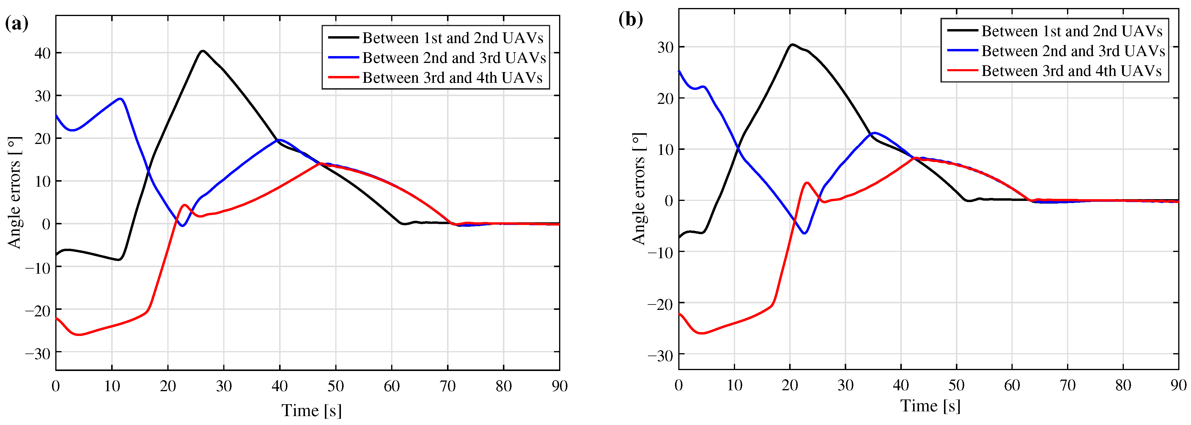
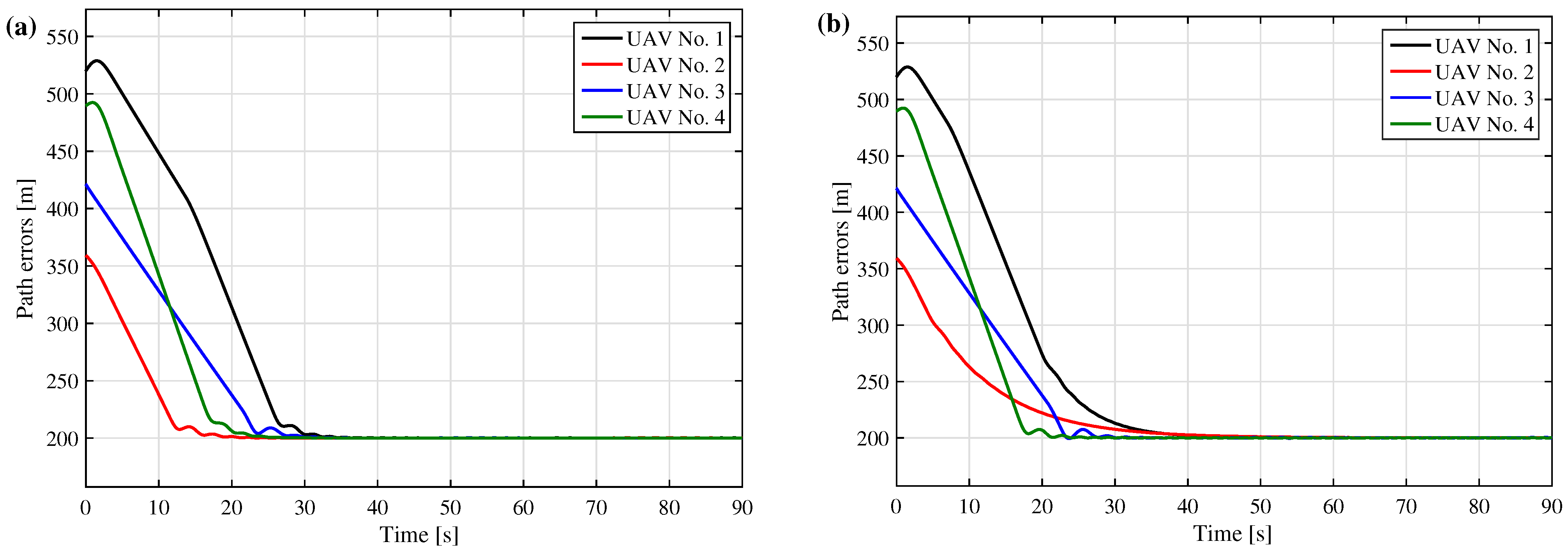
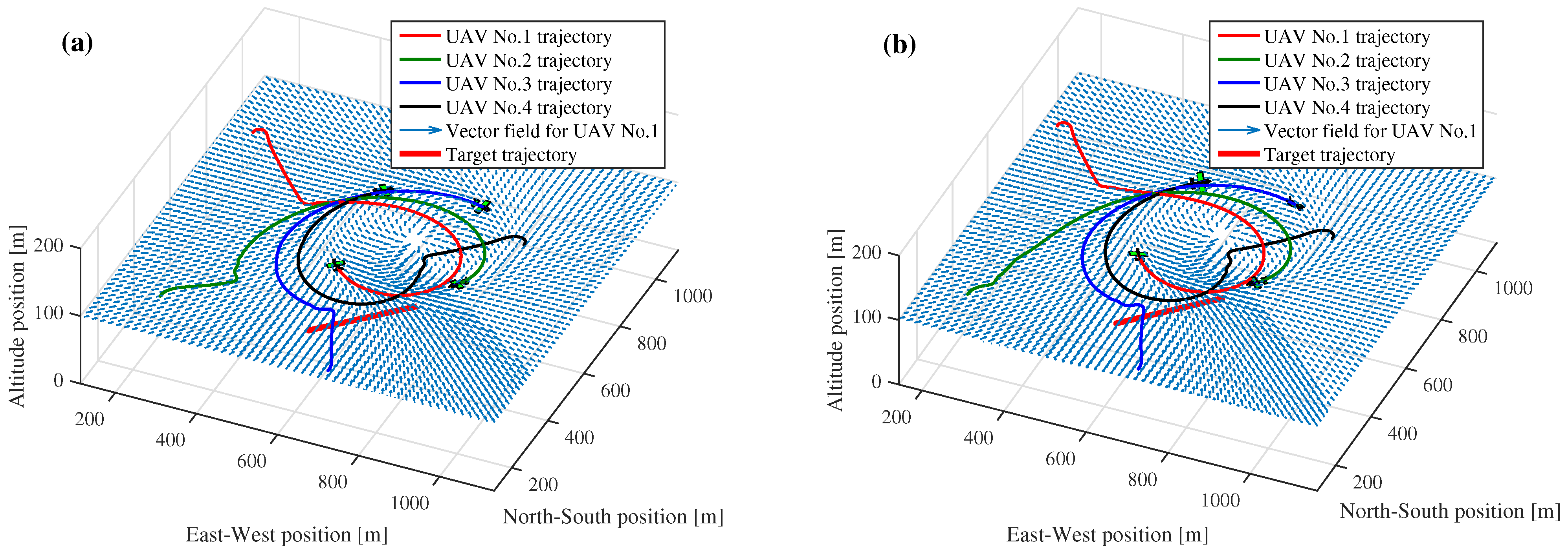
Figure 2 shows UAV formation angular errors before and after optimization. As can be seen in the graphs, optimization enabled the formation to reach the pre-specified relative angular positions somewhat faster. Figure 3 shows how path errors changed in the UAV formation. As can be seen from the graphs, UAV1 and UAV2 showed the most drastic changes. Apparently, transient trajectories before and after optimization are different (Figure 4). Even though the trajectories look similar in the figure, they are still different. That is especially noticeable in the trajectories for UAV1 and UAV2.
Notably, although the controller coefficients were tuned only for the control law (3), the fitness function included the total angular error of the formation (4). The reason for this was that control by path errors is tied to control by angular errors in a decentralized UAV formation system. This connection can be seen, among other things, in the simulation results in Figure 2.

6. Conclusions

The paper demonstrates a successful use of particle swarm optimization for target encirclement and tracking by a UAV formation. The formation itself was a vector fieldcontrolled decentralized formation. Simulations showed a reduction in the proposed fitness function as well as a change in the pattern of transient trajectories. A close connection was found between optimizing the path error controller optimization and the quality of transient trajectories for angular errors in the UAV formation.

Funding

This work was supported by the Ministry of Science and Higher Education of the Russian Federation (Agreement No. 075-15-2021-1016).

Institutional Review Board Statement

Not applicable.

Informed Consent Statement

Not applicable.

Data Availability Statement

Not applicable.

Conflicts of Interest

The authors declare no conflict of interest.

References

  1. Darintsev, O.V.; Yudintsev, B.S.; Alekseev, A.Y.; Bogdanov, D.R.; Migranov, A.B. Methods of a Heterogeneous Multi-agent Robotic System Group Control. Procedia Comput. Sci. 2019, 150, 687–694. [Google Scholar] [CrossRef]
  2. Ivanov, D.Y. Distribution of roles in groups of robots with limited communications based on the swarm interaction. Procedia Comput. Sci. 2019, 150, 518–523. [Google Scholar] [CrossRef]
  3. Veselov, G.; Sklyrov, A.; Mushenko, A.; Sklyrov, S. Synergetic Control of a Mobile Robot Group. In Proceedings of the 2014 2nd International Conference on Artificial Intelligence, Modelling and Simulation, Madrid, Spain, 18–20 November 2014; pp. 155–160. [Google Scholar] [CrossRef]
  4. Bennet, D.J.; McInnes, C.R.; Suzuki, M.; Uchiyama, K. Autonomous Three-Dimensional Formation Flight for a Swarm of Unmanned Aerial Vehicles. J. Guid. Control Dyn. 2011, 34, 1899–1908. [Google Scholar] [CrossRef] [Green Version]
  5. Milyakov, D.A.; Merkulov, V.I. The Approach to Managing a Group of UAVs as a System with Distributed Parameters. Procedia Comput. Sci. 2019, 150, 39–45. [Google Scholar] [CrossRef]
  6. Diveev, A.I.; Shmalko, E.Y.; Hussein, O. Synthesized Optimal Control of Group Interaction of Quadrocopters Based on Multi-Point Stabilization. Instrum. Eng. 2020, 133, 114–133. [Google Scholar] [CrossRef]
  7. Titkov, I.P.; Karpunin, A. Collision-aware formation assignment of quadrotors. Procedia Comput. Sci. 2021, 186, 727–735. [Google Scholar] [CrossRef]
  8. Pavlovskii, V.E.; Pavlovskii, V.V. A mathematical model of a 2D homogeneous swarm of robots. Sci. Tech. Inf. Process. 2016, 43, 306–314. [Google Scholar] [CrossRef]
  9. Senotov, V.D.; Aliseychik, A.P.; Pavlovsky, E.V.; Podoprosvetov, A.V.; Orlov, I.A. Algorithms for swarm decentralized motion control of group of robots with a differential drive. Keldysh Inst. Prepr. 2020, 123, 1–39. [Google Scholar] [CrossRef]
  10. Zakiev, A.; Tsoy, T.; Magid, E. Swarm robotics: Remarks on terminology and classification. In Proceedings of the Interactive Collaborative Robotics: Third International Conference, ICR 2018, Leipzig, Germany, 18–22 September 2018; pp. 291–300. [Google Scholar]
  11. Ollervides-Vazquez, E.J.; Rojo-Rodriguez, E.G.; Garcia-Salazar, O.; Amezquita-Brooks, L.; Castillo, P.; Santibañez, V. A sectorial fuzzy consensus algorithm for the formation flight of multiple quadrotor unmanned aerial vehicles. Int. J. Micro Air Veh. 2020, 12, 1756829320973579. [Google Scholar] [CrossRef]
  12. Muslimov, T.Z.; Munasypov, R.A. Multi-UAV cooperative target tracking via consensus-based guidance vector fields and fuzzy MRAC. Aircr. Eng. Aerosp. Technol. 2021, 93, 1204–1212. [Google Scholar] [CrossRef]
  13. Diveev, A.; Shmalko, E. Hybrid evolutionary algorithm for synthesized optimal control problem for group of interacting robots. In Proceedings of the 2019 6th International Conference on Control, Decision and Information Technologies (CoDIT), Paris, France, 23–26 April 2019; pp. 876–881. [Google Scholar] [CrossRef]
  14. Bożko, A.; Ambroziak, L.; Pawluszewicz, E. Genetic Algorithm for Parameters Tuning of Two Stage Switching Controller for UAV Autonomous Formation Flight. Adv. Intell. Syst. Comput. 2021, 1390, 154–165. [Google Scholar]
  15. Kim, M. Error Dynamics-Based Guidance Law for Target Observation using Multiple UAVs with Phase Angle Constraints via Evolutionary Algorithms. J. Control Autom. Electr. Syst. 2021, 32, 1510–1520. [Google Scholar] [CrossRef]
  16. Ali, Z.A.; Zhangang, H. Multi-unmanned aerial vehicle swarm formation control using hybrid strategy. Trans. Inst. Meas. Control 2021, 43, 2689–2701. [Google Scholar] [CrossRef]
  17. Ali, Z.A.; Han, Z.; Masood, R.J. Collective Motion and Self-Organization of a Swarm of UAVs: A Cluster-Based Architecture. Sensors 2021, 21, 3820. [Google Scholar] [CrossRef] [PubMed]
  18. Derrouaoui, S.H.; Bouzid, Y.; Guiatni, M. PSO Based Optimal Gain Scheduling Backstepping Flight Controller Design for a Transformable Quadrotor. J. Intell. Robot. Syst. 2021, 102, 67. [Google Scholar] [CrossRef]
  19. Kiyak, E. Tuning of controller for an aircraft flight control system based on particle swarm optimization. Aircr. Eng. Aerosp. Technol. 2016, 88, 799–809. [Google Scholar] [CrossRef]
  20. Saribas, H.; Kahvecioglu, S. PSO and GA tuned conventional and fractional order PID controllers for quadrotor control. Aircr. Eng. Aerosp. Technol. 2021, 93, 1243–1253. [Google Scholar] [CrossRef]
  21. Biantoro, N.; Halim, M.; Nazaruddin, Y.Y.; Juliastuti, E. PSO-based Optimization of Formation Control and Obstacle Avoidance for Multiple Quadrotors. In Proceedings of the 2021 International Conference on Instrumentation, Control and Automation (ICA), Bandung, Indonesia, 25–27 August 2021; pp. 133–137. [Google Scholar] [CrossRef]
  22. Hoang, V.T.; Phung, M.D.; Dinh, T.H.; Zhu, Q.; Ha, Q.P. Reconfigurable Multi-UAV Formation Using Angle-Encoded PSO. In Proceedings of the 2019 IEEE 15th International Conference on Automation Science and Engineering (CASE), Vancouver, BC, Canada, 22–26 August 2019; pp. 1670–1675. [Google Scholar] [CrossRef] [Green Version]
  23. Sruthy, A.N.; Jacob, J.; Ramch, R. PSO Based Integral Backtepping Control for Leader-Follower Quadrotors. In Proceedings of the 2020 Fourth International Conference on Inventive Systems and Control (ICISC), Coimbatore, India, 8–10 January 2020; pp. 466–471. [Google Scholar] [CrossRef]
  24. Vijayakumari, D.M.; Kim, S.; Suk, J.; Mo, H. Receding-Horizon Trajectory Planning for Multiple UAVs Using Particle Swarm Optimization; AIAA Scitech 2019 Forum; American Institute of Aeronautics and Astronautics: Reston, VA, USA, 2019. [Google Scholar] [CrossRef]
  25. Patley, A.; Bhatt, A.; Maity, A.; Das, K.; Ranjan Kumar, S. Modified Particle Swarm Optimization Based Path Planning for Multi-Uav Formation; AIAA Scitech 2019 Forum; American Institute of Aeronautics and Astronautics: Reston, VA, USA, 2019. [Google Scholar] [CrossRef]
  26. Skrzypecki, S.; Tarapata, Z.; Pierzchała, D. Combined PSO Methods for UAVs Swarm Modelling and Simulation. In Proceedings of the Modelling and Simulation for Autonomous Systems: 6th International Conference, MESAS 2019, Palermo, Italy, 29–31 October 2019; pp. 11–25. [Google Scholar]
  27. Muslimov, T.Z.; Munasypov, R.A. Coordinated UAV Standoff Tracking of Moving Target Based on Lyapunov Vector Fields. In Proceedings of the 2020 International Conference Nonlinearity, Information and Robotics (NIR), Innopolis, Russia, 3–6 December 2020; pp. 1–5. [Google Scholar] [CrossRef]
  28. Muslimov, T. Application of Genetic Algorithm for Vector Field Guidance Optimization in a UAV Collective Circumnavigation Scenario. In Robotics in Natural Settings: CLAWAR 2022; Springer International Publishing: Cham, Switzerland, 2022. [Google Scholar]
  29. Beard, R.W.; McLain, T.W. Small Unmanned Aircraft: Theory and Practice; Princeton University Press: Princeton, NJ, USA, 2012. [Google Scholar]
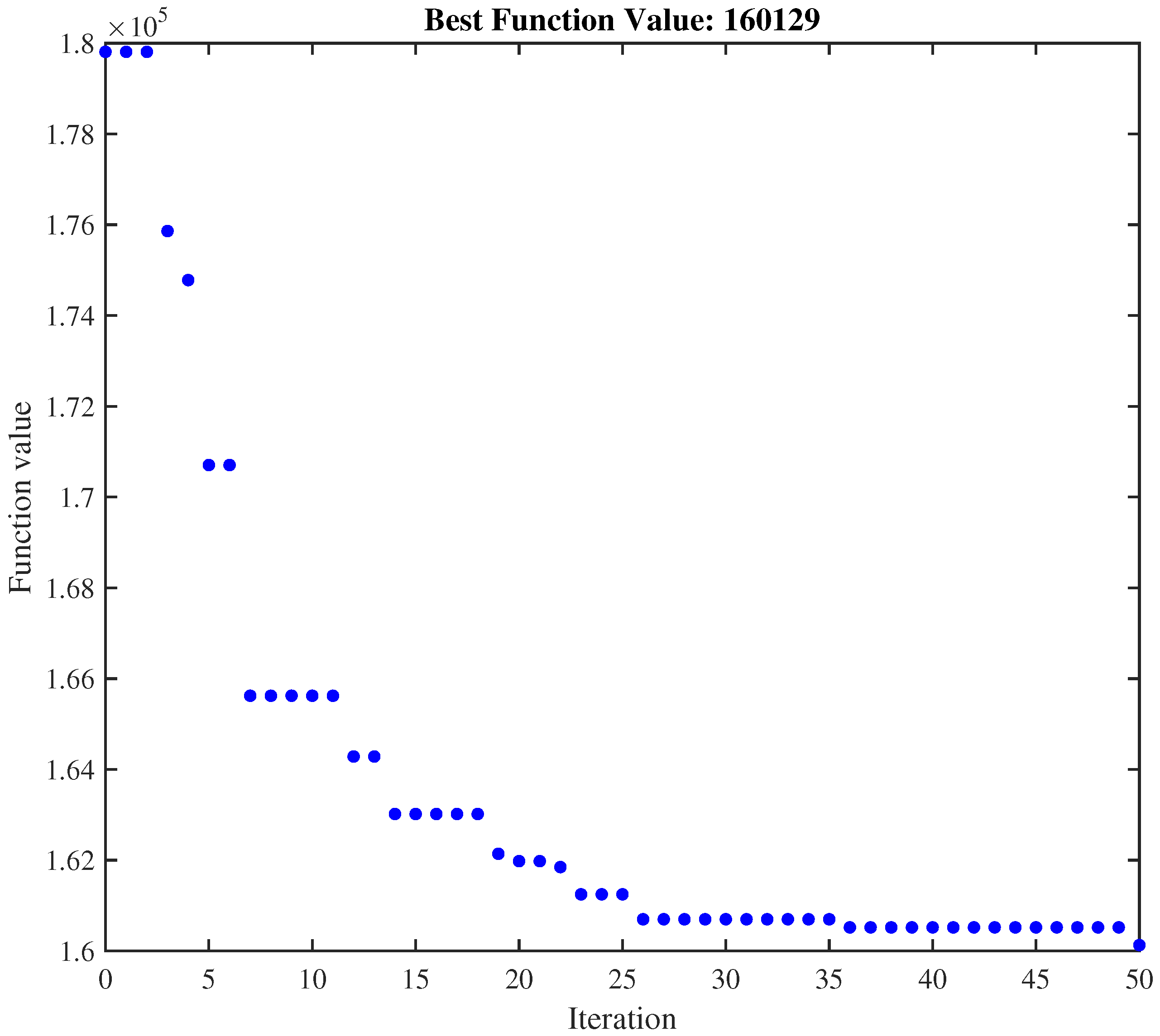
Figure 1. Fitness function value change during simulation.
Engproc 33 00015 g001
Figure 2. UAV angular errors at time t = 90 s . (a) Angular errors before particle swarm optimization; (b) angular errors after particle swarm optimization.
Engproc 33 00015 g002
Figure 3. UAV path errors at time t = 90 s . (a) Path errors before particle swarm optimization; (b) path errors after particle swarm optimization.
Engproc 33 00015 g003
Figure 4. UAV formation trajectories at time t = 90 s . (a) Trajectories before particle swarm optimization; (b) trajectories after particle swarm optimization.
Engproc 33 00015 g004
Table 1. Simulation parameters.
ParameterSymbolValues
Initial UAV heading vector (rad) Ø 0 0 0 0 0 T
Initial UAV speed vector (m/s) v 0 13 13 13 13 T
Circular path radius (m) ρ 200
Initial target coordinates (m) c = c e 0 c n 0 h 0 T 500 500 100 T
Ultimate cruise speed of the formation in case of a stationary target (m/s)v13
Target speed (m/s) v target 2
Target course angle (rad) χ target π π 4 4
Vector of initial UAV coordinates in the ICS (m)   p 1 0 , p 2 0 , p 3 0 , p 4 0 180 910 100 T , 245 247 100 T , 710 135 100 T , 915 760 100 T
Desired inter-UAV phase shift angles P θ d 270 260 290 T
Initial tuning coefficients k θ , k θ ˙ , k o i , k o ˙ i 35, 15, 1, 2
Disclaimer/Publisher’s Note: The statements, opinions and data contained in all publications are solely those of the individual author(s) and contributor(s) and not of MDPI and/or the editor(s). MDPI and/or the editor(s) disclaim responsibility for any injury to people or property resulting from any ideas, methods, instructions or products referred to in the content.