1. Introduction
Cellular networks at higher frequency spectra (such as mmWave band) provide high data rates due to their wide bandwidth. However, the propagation at this band experiences severe path loss and penetration loss, making the links highly vulnerable to blockage [
1,
2]. Moreover, future networks are envisaged to be dense, i.e., having more BSs per unit area for increased network capacity. In such a dense network, user equipment (UE) lies in the communication proximity of a BS, and the link lengths are equivalent to the BS heights. Therefore it is important to model a three-dimensional (3D) network by taking into account the BS height [
3,
4].
Prior works have mostly focused on two-dimensional mmWave networks [
5,
6,
7]. Recently, some literature has also contributed to the 3D network model of mmWave and terahertz band networks [
3,
4,
8,
9,
10,
11,
12]. The work in [
8,
12] consider a 3D ultra-dense network with line-of-sight (LOS) and non-line-of-sight(NLOS) propagation but did not consider BS and UE antenna gains. Whereas [
3] considers an outdoor mmWave network and takes into account the height of blockage and BS and UE antenna heights but does not take into account elevation angles. The work in [
10] considers the height of BS and 3D antenna radiation patterns but does not consider the height of building blockages. Finally, [
11] considers a 3D terahertz indoor wireless network. Authors in [
9] present a generalized system model that includes blockages and BS and UE antenna arrays in a 3D framework. It has also been shown that in a dense network with random UE height and at high frequency with more penetration losses, the uniform cylindrical array (UcylA) is a preferred choice.
In contrast to all the previous works mentioned above, we present a system model that considers a 3D network with BS and UE equipped with UcylA antenna radiation pattern accounting for their elevation angles. We also consider the height of building blockages as well as the BS. As compared to the work in [
9] that does not consider the features of building blockage, our system model in this work also characterizes the impact of blockage with different heights and widths.
2. System Model
In this work, the downlink of outdoor dense mmWave network is considered with BSs and UEs distributed following the Poisson point process (PPP) having densities
λ and
, respectively. Rectangular building blockages are distributed following another independent PPP. We conduct our analysis for a typical UE placed at the origin. Minimum path loss association is assumed between a UE and its serving BS. The network employs universal frequency reuse, and at any time, each BS has at least one active user to serve within its coverage area. Due to blockages, the link between typical UE and its serving BS is either unblocked, i.e., LOS with probability
, or blocked, i.e., non-LOS with probability
. For separate path loss exponents,
are used for LOS and NLOS paths according to the functions defined below [
3],
where,
β depends on the length and width of the building blockage, and δ depends on exponentially distributed building height with mean
and is given by
[
3].
The fading on the LOS and NLOS links follow independent Nakagami distribution with the parameters denoted by
and
, respectively. Each BS is assumed to be mounted at a height
h above the ground. The BS is equipped with a uniform cylindrical array (UcylA) that can be decomposed into two compound arrays, i.e., uniform circular array (UCA) on a horizontal plane with array gain
and uniform linear array (ULA) on a vertical plane with gain
. Therefore, the UcylA gain is given as
, with total antenna elements
, where
are the antenna elements in UCA and
are the antenna elements in ULA. The gains from UCA and ULA are given by [
9]:
3. Analysis of SINR Coverage Probability
The SINR coverage probability, defined as the probability of having SINR greater than a certain threshold value (
T), is mathematically given by
. For the LOS link between typical UE and reference BS, the received SINR at BS at a random distance
r is:
Here, represents the direction of the intended UE and represents the direction of interfering BS at a distance . represents noise power, and are the gamma distributed fading power on the desired link and interfering links, respectively. The beamforming gains are defined in terms of azimuth and elevation angles and is defined in (1).
The distance distribution between UE and LOS or NLOS serving BS is obtained as follows (the proof is omitted for brevity but can be obtained from [
5]):
The final coverage probability expression for
is given below,
Here,
represents the Laplace transforms (LT) of interference is obtained as follows:
Here, and similar expressions for LT can be obtained for the NLOS link typical UE and reference BS.
4. Numerical Results and Discussions
This section presents the numerical simulation of derived expressions according to the system parameter listed in
Table 1.
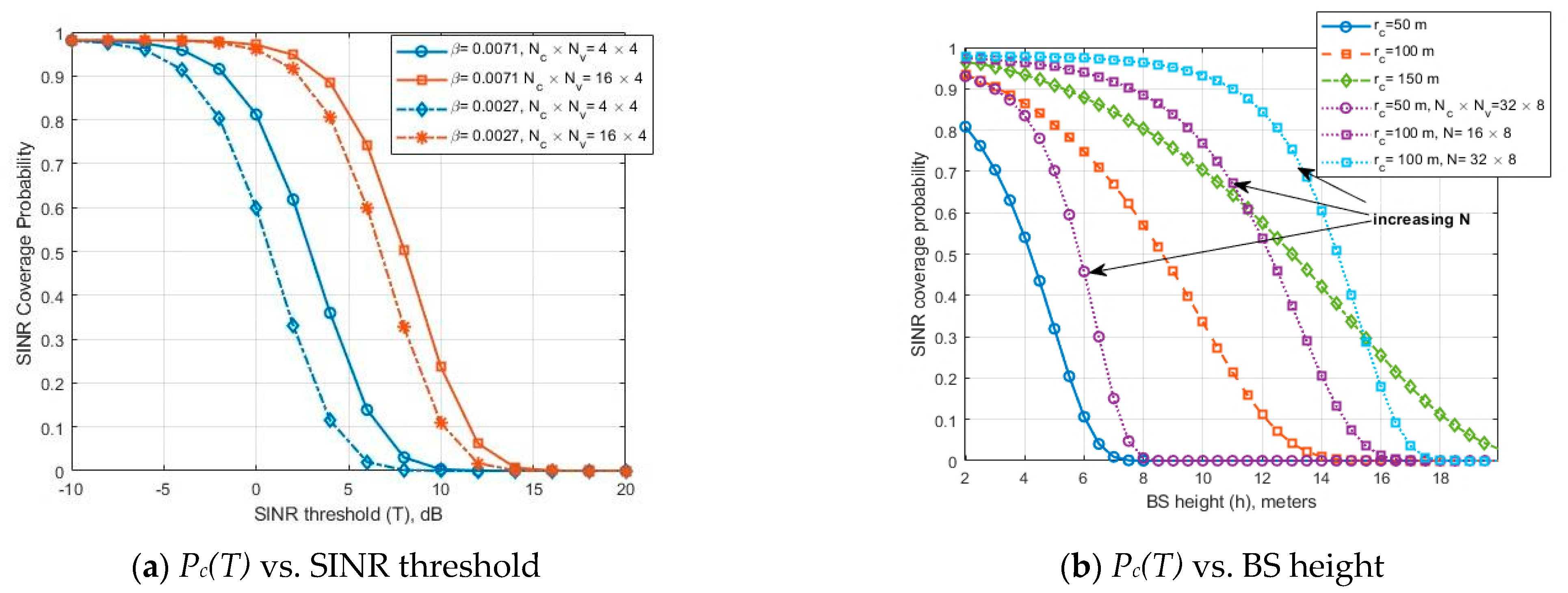
In
Figure 1a, we examine the impact of UcylA at blockage parameters (
β = 0.0071, 0.0027) representing different blockage densities. It can be observed that at high blockage density (
β = 0.0027), the coverage is improved by using a high configuration of the antenna elements.
Figure 1b presents the SINR coverage probability with respect to BS height at different cell radius
= 50, 100, 150 m for an antenna configuration
= 16 × 4. It can be seen that at these radii, the coverage probability reduces as the height of BS is increased; because of increased interference power from nearby elevated BSs. The detrimental effect of height is more severe in the case of low cell radius (
= 50 m). It can also be observed that for the case of
= 50 m and 100 m, and at fixed BS height (e.g., 6 m), a significant increase in coverage probability can be obtained by increasing the antenna array size to 16 × 8 or 32 × 8. However, this figure also dictates that at a particular radius, there is a certain range of BS height for which coverage probability can be improved by increasing the array elements, after which coverage probability falls to zero. This gives designers a choice to select the optimum configuration of array size at a certain BS height for different cell radii.
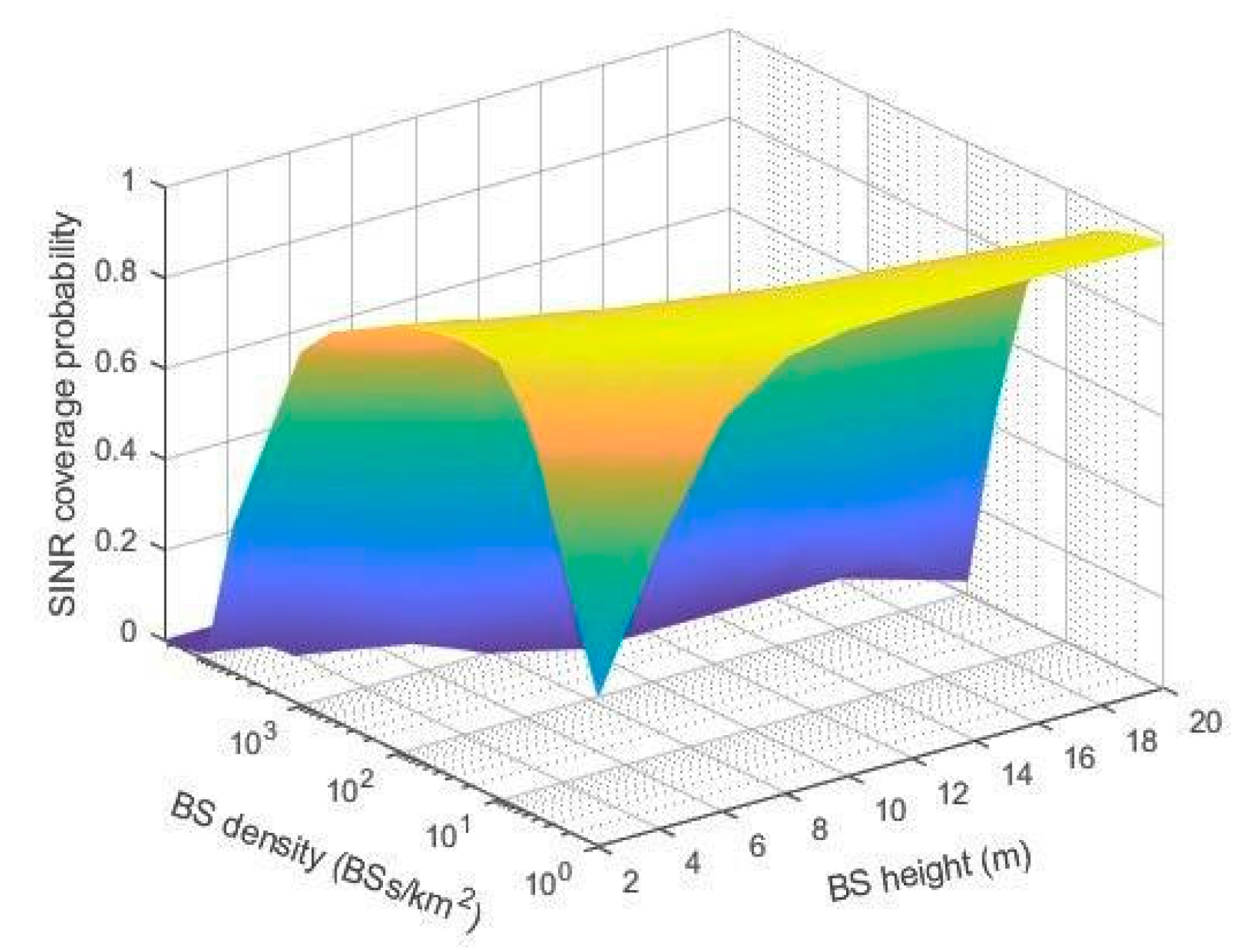
In
Figure 2, we present a 3D plot to observe the joint impact of BS height and BS density on the SINR coverage probability. It can be seen that there is a certain BS height at a particular BS density that maximizes coverage probability. Consequently, this provides network designers a choice to jointly optimize the BS density to BS height tradeoff.
5. Conclusions
In this work, we present a 3D system model for a dense mmWave cellular network that takes into account the height of BS and building blockage. A uniform cylindrical antenna array is employed at BS and UE. We derive mathematical expressions for SINR coverage probability that is dependent on various network parameters, such as BS density, height, and antenna array size. Results show that the coverage performance is affected by the proper choice of BS antenna height for a given cell radius and BS density. The array size is shown to increase the coverage probability within a certain range of BS height only, after which it reduces to zero due to increased network interference.
Author Contributions
H.M. formulated the system design, developed a theoretical model, performed numerical analysis, and wrote the manuscript. I.A. verified the analytical methods and findings, provided useful feedback, and reviewed the manuscript. All authors have read and agreed to the published version of the manuscript.
Funding
This research received no external funding.
Institutional Review Board Statement
Not applicable.
Informed Consent Statement
Not applicable.
Data Availability Statement
Not applicable.
Conflicts of Interest
The authors declare no conflict of interest.
References
- Pi, Z.; Khan, F. An introduction to millimeter-wave mobile broadband systems. IEEE Commun. Mag. 2011, 49, 101–107. [Google Scholar] [CrossRef]
- Rangan, S.; Rappaport, T.S.; Erkip, E. Millimeter-wave cellular wireless networks: Potentials and challenges. Proc. IEEE 2014, 102, 366–385. [Google Scholar] [CrossRef]
- Chen, C.; Zhang, J.; Chu, X.; Zhang, J. On the Optimal Base-Station Height in mmWave Small-Cell Networks Considering Cylindrical Blockage Effects. IEEE Trans. Veh. Technol. 2021, 70, 9588–9592. [Google Scholar] [CrossRef]
- Comisso, M.; Babich, F. Coverage Analysis for 2D/3D Millimeter Wave Peer-to-Peer Networks. IEEE Trans. Wirel. Commun. 2019, 18, 3613–3627. [Google Scholar] [CrossRef]
- Bai, T.; Heath, R.W. Coverage and Rate Analysis for Millimeter-Wave Cellular Networks. IEEE Trans. Wirel. Commun. 2015, 14, 1100–1114. [Google Scholar] [CrossRef]
- Di Renzo, M. Stochastic geometry modeling and analysis of multi-tier millimeter wave cellular networks. IEEE Trans. Wirel. Commun. 2015, 14, 5038–5057. [Google Scholar] [CrossRef]
- Turgut, E.; Gursoy, M.C. Coverage in heterogeneous downlink millimeter wave cellular networks. IEEE Trans. Commun. 2017, 65, 4463–4477. [Google Scholar] [CrossRef]
- Cho, H.; Liu, C.; Lee, J.; Noh, T.; Quek, T.Q.S. Impact of Elevated Base Stations on the Ultra-Dense Networks. IEEE Commun. Lett. 2018, 22, 1265–1271. [Google Scholar] [CrossRef]
- Aghazadeh Ayoubi, R.; Spagnolini, U. Performance of Dense Wireless Networks in 5G and beyond Using Stochastic Geometry. Mathematics 2022, 10, 1156. [Google Scholar] [CrossRef]
- Baianifar, M.; Razavizadeh, S.M.; Khavari-Moghaddam, S.; Svensson, T. Effect of Users Height Distribution on the Coverage of mmWave Cellular Networks With 3D Beamforming. IEEE Access 2019, 7, 68091–68105. [Google Scholar] [CrossRef]
- Shafie, A.; Yang, N.; Sun, Z.; Durrani, S. Coverage analysis for 3D terahertz communication systems with blockage and directional antennas. IEEE J. Sel. Areas Commun. 2020, 39, 20968592. [Google Scholar] [CrossRef]
- Arnau, J.; Atzeni, I.; Kountouris, M. Impact of LOS/NLOS propagation and path loss in ultra-dense cellular networks. In Proceedings of the 2016 IEEE International Conference on Communications (ICC), Kuala Lumpur, Malaysia, 22–27 May 2016; pp. 1–6. [Google Scholar]
| Disclaimer/Publisher’s Note: The statements, opinions and data contained in all publications are solely those of the individual author(s) and contributor(s) and not of MDPI and/or the editor(s). MDPI and/or the editor(s) disclaim responsibility for any injury to people or property resulting from any ideas, methods, instructions or products referred to in the content. |
© 2023 by the authors. Licensee MDPI, Basel, Switzerland. This article is an open access article distributed under the terms and conditions of the Creative Commons Attribution (CC BY) license (https://creativecommons.org/licenses/by/4.0/).


