1. Introduction
There have been various advancements in internal combustion engines, primarily due to emissions standards and regulations. Since harmful gases such as are released in case of incomplete combustion, Variable Valve Timing is employed to operate the valves for the intake and exhaust of fuel, air, and exhaust gases in the combustion chamber. As a result, emissions can be reduced, which also leads to fuel conservation and increased efficiency.
In general, VVTs are hydraulic systems. Hydraulic VVTs, however, have limitations, which include the change in response and performance characteristics due to changes in operating conditions such as temperature and oil viscosity. This led to the study of other types of VVT systems, such as electro-pneumatic, electro-magnetic, cam-less, and electric planetary systems. Comparing electric motor-driven VVT systems to hydraulic VVT systems has led to concur that electrical VVT systems are independent of engine oil pressure, hence offering better operational performance and emissions.
As far as closed-loop control design for the VVT systems is concerned, a linear controller using loop-shaping has been investigated by Paden et al. [
1]. Similarly, in [
2], a feedforward/feedback controller was studied for an HCCI combustion engine. Moreover, multi-parametric model predictive control has widely been used for the design of VVT systems [
3,
4]. Finally, in [
5,
6], an
, and
controller was investigated in the context of VVT control. GA optimization, however, has not been used for the control design of electric planetary VVT, but it is an effective approach due to its ability to search through large design spaces and determine optimal solutions. Therefore, in this study, a GA-based VVT controller is investigated. In correspondence, a root locus-tuned PD controller is also developed and performance is compared between these two controllers.
2. Linear Model Development
The simplified linear VVT model is explained in [
5,
6]. In this study, however, certain assumptions are made; for example, the dynamics of the ring gear are ignored because of the high inertia of the engine flywheel and crankshaft; the camshaft load which is the disturbance parameter in the control system is also ignored for model simplification.
2.1. Motor Dynamics
The relationship between the voltage drop across the armature circuit and the torque produced by the motor is represented by
in Equation (1). Armature resistance, inductance, motor torque constant, and back emf of the motor are represented by
,
,
and
respectively.
2.2. Planetary Gear System Dynamics
For model simplification, the planetary system is treated as having only one planet gear and the friction present is ignored. Equation (2) represents the transfer function
, which shows the relationship between the motor speed input to the planetary gear system and the output to the camshaft.
Here,
J is the sum of the inertia of the carrier and the equivalent inertia of the gears.
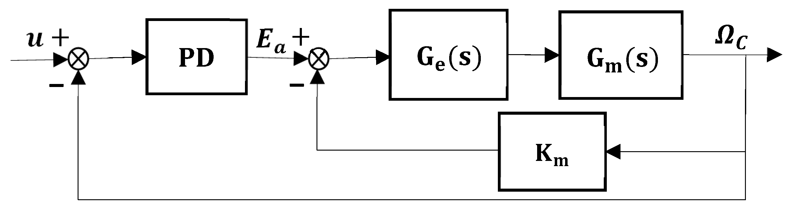
is the friction coefficient, which depends on the engine oil viscosity, and it changes due to temperature. The block diagram of the VVT model under study is shown in
Figure 1.
3. Controller Design
For closed-loop control design, a PD controller is developed. The resulting transfer function which represents the system plant without the back emf (
) is provided as
Here,
is the open-loop VVT transfer function without the back emf
.
Equation (4) is used to determine the overall open loop transfer function shown in Equation (5).
The value of
, which is the frictional coefficient, depends on the viscosity of oil and ranges from 0.5
to 2
. For normal working conditions, it is taken as
. Putting the parameter values shown in
Table 1 into Equation (5), we obtain the open- and closed-loop transfer function as shown in Equations (6) and (7). From the analysis of these equations, the system is determined to be stable. The root locus plot is shown in
Figure 2a, where the poles lie at −
and −
.
PD Controller Design
A Proportional Derivative (PD) controller is designed to achieve the desired performance. The general form of the PD controller is provided as . A PD controller was chosen because of the overshoot requirements. The performance requirements were set to be a maximum overshoot of 5% and a settling time of 0.01 s.
Using the conventional root-locus tuning method, the proportional and derivative gains were determined to be 10 and 0.05, respectively. The root locus of the system with the controller is shown in
Figure 2b. The open- and closed-loop transfer functions alongside the PD controller are shown in Equations (8) and (9), respectively.
The designed PD controller, as discussed before, will be used as a baseline controller for comparison with an optimal controller.
4. Controller Optimization Using Genetic Algorithm
GA is a search-centered optimization technique which is based on the Darwinian theory of genetic evolution. It is significantly useful in the optimization of PID controller parameters. The optimization performance of the controller design using GA is mainly dependent on the selection of an appropriate cost function. For this system, the Integral of Time-weighted Absolute Error (ITEA) is used as the cost function. Equation (10) represents the mathematical expression of the cost function, where the error signal of the function is denoted by
. Using the ITEA error function, proportional and derivative gains are determined for the VVT system.
The setup parameters of the GA optimization are shown in
Table 2. The values of
and
obtained using GA are
and
, respectively. Using these values, the open-loop and closed-loop transfer functions are shown in Equations (11) and (12).
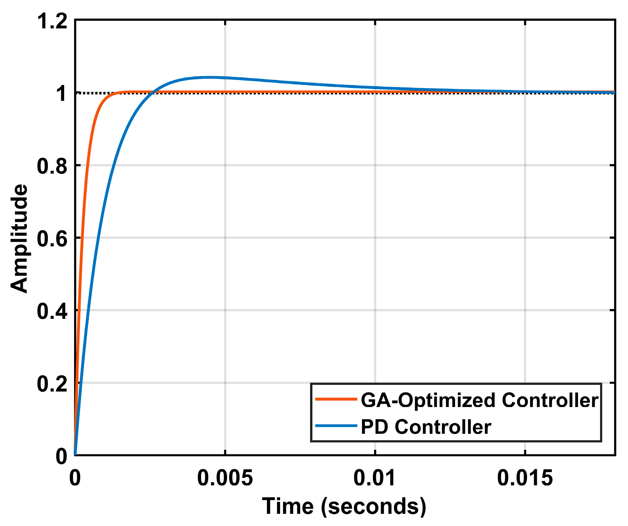
The response of the GA-optimized VVT system for a step input is shown in
Figure 3. The step response shows that the performance of the system has considerably increased. The improved settling time and rise time are determined to be 0.0009 s and 0.000568 s. The overshoot was calculated to be 0.34%, while the steady-state error was calculated to be 0.0017.
5. Conclusions
In this study, a motor-driven planetary VVT controller is explained. A PD controller was designed using the root locus technique and served as the baseline controller in comparison to a GA-optimized controller. Simulations are carried out in which the GA-optimized controller showed an improved and optimal performance.
The linear model of the electric planetary VVT system is led in line with some assumptions and simplifications. However, in real world, a non-linear model is followed with high engine speeds for maximum power and fuel efficiency at low RPM. Therefore, in future, an optimal controller can be developed consequent to these changing parameters and non-linear behavior, which can be verified by its practical implementation.
Author Contributions
Conceptualization by A.u.R. and A.T. Methodology, software validation, formal analysis, investigation, and draft preparation by A.u.R. Overall, this study has been completed under the supervision of A.T., who has also reviewed and edited the paper. All authors have read and agreed to the published version of the manuscript.
Funding
This research received no external funding.
Institutional Review Board Statement
Not applicable.
Informed Consent Statement
Not applicable.
Data Availability Statement
The data presented in this study are available on request.
Conflicts of Interest
The authors declare no conflict of interest.
References
- Paden, B.A.; Snyder, S.T.; Paden, B.E.; Ricci, M.R. Modeling and Control of an Electromagnetic Variable Valve Actuation System. IEEE/ASME Trans. Mechatron. 2015, 20, 2654–2665. [Google Scholar] [CrossRef]
- Ebrahimi, K.; Schramm, A.; Koch, C.R. Feedforward/Feedback control of HCCI combustion timing. In Proceedings of the 2014 American Control Conference, Portland, OR, USA, 4–6 June 2014; pp. 831–836. [Google Scholar] [CrossRef]
- Lee, J.; Chang, H.J. Multi-parametric model predictive control for variable valve timing. In Proceedings of the 2017 17th International Conference on Control, Automation, and Systems (ICCAS), Jeju, Republic of Korea, 18–21 October 2017; pp. 1218–1221. [Google Scholar] [CrossRef]
- Kristoffersson, I. Model Predictive Control of a Turbocharged Engine. Master’s Thesis, Institute for Signals, Sensors and Systems (S3) at KTH-Royal Institute of Technology, General Motors Powertrain, Stockholm, Sweden, 2006. XR-EE-RT 2006:005. Available online: http://kth.diva-portal.org/smash/get/diva2:576329/FULLTEXT01.pdf (accessed on 8 January 2022).
- White, A.; Choi, J.; Zhu, G. Dynamic, output-feedback, gain-scheduling control of an electric variable valve timing system. In Proceedings of the 2013 American Control Conference, Washington, DC, USA, 17–19 June 2013; pp. 3619–3624. [Google Scholar] [CrossRef]
- Ren, Z.; Zhu, G.G. Modeling and control of an electric variable valve timing system for SI and HCCI combustion mode transition. In Proceedings of the 2011 American Control Conference, San Francisco, CA, USA, 29 June–1 July 2011; pp. 979–984. [Google Scholar] [CrossRef]
| Disclaimer/Publisher’s Note: The statements, opinions and data contained in all publications are solely those of the individual author(s) and contributor(s) and not of MDPI and/or the editor(s). MDPI and/or the editor(s) disclaim responsibility for any injury to people or property resulting from any ideas, methods, instructions or products referred to in the content. |
© 2023 by the authors. Licensee MDPI, Basel, Switzerland. This article is an open access article distributed under the terms and conditions of the Creative Commons Attribution (CC BY) license (https://creativecommons.org/licenses/by/4.0/).


