Proceeding Paper

An Efficient Opto Electronic Filter Design of Reflective CMY Colors for Optical Communications †

by
Shahram Hamza Manzoor
*,
Shahinza Manzoor
and
Mary Antonette Perez Diez
Department of Electrical and Computer Engineering, AIR University, Islamabad 44000, Pakistan
*
Author to whom correspondence should be addressed.
Presented at the 2nd International Conference on Emerging Trends in Electronic and Telecommunication Engineering, Karachi, Pakistan, 15–16 March 2023.
Eng. Proc. 2023, 32(1), 1; https://doi.org/10.3390/engproc2023032001
Published: 18 April 2023

Abstract

:
The discussed study presents a new type of opto-electronic color filter designed for optical communication that could revolutionize both the signal processing field and the fiber optic communication industry. The study proposes a precise structure design for three reflective color filters based on a tri-layer configuration. This design includes a titanium dioxide layer on top, a semi-conductor silicon layer in the middle, and a silicon dioxide layer at the bottom, creating a DSD structure. This design presents three different filters for pure hues, namely magenta, yellow, and cyan. One of the significant advantages of this tri-layer design is the thickness of each material layer, which plays a vital role in producing better intensity values and purity of CMY colors. This study presents the design of the new filters that could potentially have a significant impact on the display industry, and life-saving medical equipment where fiber optics with multi-layer opto-electronic color filters are used. The novelty of this study lies in its precise structure design and the potential to generate superior results compared to existing color filters. This innovative design can potentially be implemented in various fields, such as display technology and medical equipment, to enhance their performance and accuracy. Overall, this study’s contribution highlights the potential advantages and usages of the proposed filters in various fields.

1. Introduction

The telecommunications sector has undergone a revolution thanks to fiber optic transmission, which is now regarded as the fundamental building block of contemporary, global broadband networks [1]. Ultra-long-haul optical transmission [2], multi-terabit communication fibers [3], laser neural communication network nodes [4], and intelligent optical transmission networks [5] are only a few examples of the various fiber optic communication technologies. Light pulses are employed in all of these varieties of fiber optic communication, which transmit data from one location to another. A cylindrical structure, often comprised of a dielectric substance such as silicon [1], is what constitutes an optical fiber.
Since light serves as the medium of transmission in fiber-=optic-based communication, the purity of the light pulses, also known as light filtering or optical filters, is crucial. Every material absorbs, transmits, or reflects the incident light depending on its refractive index values, which is a natural phenomenon known as light filtering [6,7]. As a result, every material has a built-in capacity to filter particular hues. Transmissive color filtering, reflecting color filtering, and trans-reflective color filtering are possible classifications for this phenomenon [8,9]. There are several uses for these categories, including the production of photovoltaic cells, medical imaging [6,10], plasmonic devices and color filters [11,12], and many other devices [13]. Opto-electronic color-filter-based photoreaction devices frequently make use of the semiconductor thin-film-based devices’ ability to selectively absorb specific wavelengths of light [9,14].
Specially created nanostructures called spectral color filters are made of various thin-film materials [15,16]. Different sorts of visible colors are produced at the output when the thickness of the material is altered in any opto-electronic reflective color filter [17,18]. Time- and cost-effectiveness are the two key benefits of utilizing multilayer thin-film filters [19]. For thin-film color filters, there are three main design configurations: MDM [20,21], all-dielectric medium designs, and DSD. The latter produces just one resonance reaction. In comparison to MDM, it suggests that filters with DSD and an all-dielectric structure have higher reflective filter efficiency [7]. Based on the number of layers, there are numerous multilayer thin-film designs [22], such as the tri-layer-based color filter design [23]. Additionally, bi-layer Etalon color filters [8,24] that display colors in reflection or transmission are demonstrated.
The primary goal of this research is to develop a multi-layer-based opto-electronic structure with higher color purity values for efficient fiber optics communication. The major driving force behind designing this reflective color filter design is that it eliminates the requirement for an additional layer beyond the one that has been suggested, which was previously required by works [24] and Fabry-Perot etalons [23]. To obtain the desired results, extra metal layers were typically added to these works in addition to the designed filter. The proposed research is expected to yield results that can be applied to optical filter applications. By utilizing the research findings, these applications will be able to use three filters that are expected to provide superior results compared to the currently available state-of-the-art color filters. Specifically, the three filters are expected to improve color purity in the reflection spectrum, which can save time and effort in producing accurate results. With the implementation of these filters, optical filter applications can expect to achieve better color accuracy and quality, resulting in improved performance and greater efficiency.

2. Methodology

In this section, there will be a presentation of three different multi-layer color filter designs with their complete design processes.
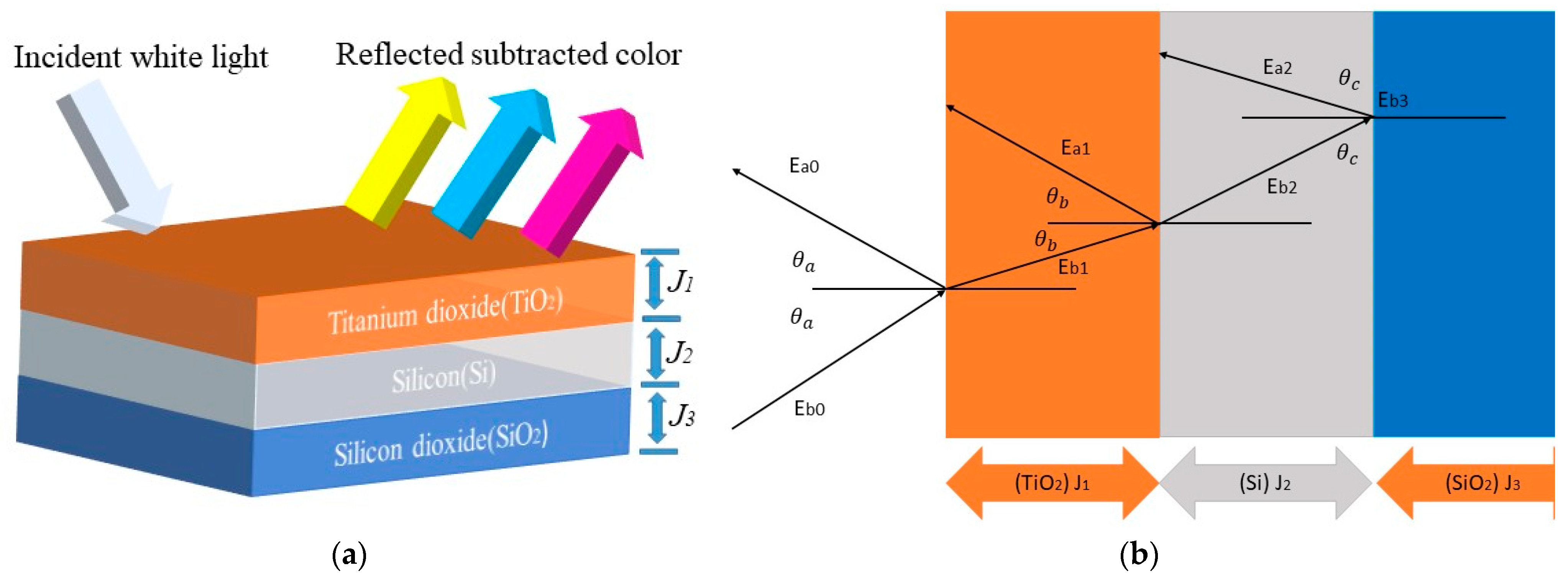
Figure 1 is a flowchart that shows the steps taken to ascertain an optically thin film stack’s anticipated color. The wavelength dependence of all the relevant parameters is taken into account, as well as the incident light’s polarization state. This is the detailed flowchart for the designing process of the multi-layer color filters. According to Table 1, the refractive index of TiO2 is 2.6142. Light bends toward normal, and some of it is reflected back when it is incident at a 90-degree angle from the air (a medium with a low refractive index) to titanium dioxide (a medium with a high refractive index). The silicon layer is then reached by the light, which has a refractive index of 3.9 values. After that, it bends and refracts once more, reflecting back a portion of itself. As illustrated in Figure 2a,b, the lowest layer, silicon dioxide, has a low refractive index value and allows light to pass through.
Derivation of the reflection equation/algorithm used in designing the proposed tri-layer filter from a TiO2-Si-SiO2 multilayer structure according to Figure 2b:
E b 1 = t r 01 E b 0 + r f 10 E a 1
where b 1 = j F O / B K , therefore E j F O / B K shows electric field j indicated in the medium, and FO is forward motion, and BK is backward motion of electric field in the medium.
t r k h = 2 h k c o s θ k h k c o s θ k + h h c o s θ h
Equation (2) indicates the transmissions co-efficient for s-polarization.
t r k h = 2 h k c o s θ k h h c o s θ k h k c o s θ h
Equation (3) indicates the transmissions co-efficient for p-polarization.
r f k h = h k c o s θ k h h c o s θ h h k c o s θ k + h h c o s θ h
Equation (4) indicates the reflection co-efficient for s-polarization.
r f k h = h h c o s θ k h k c o s θ h h h c o s θ k + h k c o s θ h
Equation (5) indicates the reflection co-efficient for p-polarization.
h k is the refractive index of medium k.
β k = 2 π λ h k d k c o s θ k
d k is the thickness of material layers.
θ k is the incident angle on medium.
Applying and rearranging r f 10 = r f 01
E b 0 = 1 t r 01 × ( E b 1 + r f 01 E a 1 )
E a 0 = r f 01 E b 0 + t r 10 E a 1
This equation is also from Figure 2b.
Rearranging and applying t r 10 = 1 r f 01 2 t r 01
E b 0 = 1 t r 01 × ( E a 1 + r f 01 E b 1 )
For the other E-field,
E b 1 = 1 t r 12 × ( E b 2 + r f 12 E a 2 ) × e j β 1
E b 2 = 1 t r 23 × ( E b 3 ) × e j β 2  
E b 2 = r f 23 t r 23 × ( E b 3 ) × e j β 2
Back substitution of (12) and (13) into (11) and (10):
E b 1 = E b 3 t r 12 t r 23 × ( e j β 2 + r f 12 r f 23 e j β 2 ) × e j β 1
E a 1 = E b 3 t r 12 t r 23 × ( r f 12 e j β 2 + r f 23 e j β 2 ) × e j β 1
Back substitution of (14) and (15) into (5) and (8):
E a 0 = E b 3 t r 01 t r 12 t r 23 × ( ( e j β 2 + r f 12 r f 23 e j β 2 ) × e j β 1 + r f 01 ( r f 12 e j β 2 + r f 23 e j β 2 ) × e j β 1 )
After rearranging we have
T r = E b 3 E b 0 = t r 01 t r 12 t r 23 e j ( β 1 + β 2 ) 1 + r f 01 r f 12 e j β 2 + ( r f 12 + r f 01 e j 2 β 1 ) r f 23 e j 2 β 2
where T r = Transmittance. Similarly,
E b 0 = E b 3 t r 01 t r 12 t r 23 × ( ( r f 01 e j β 2 + r f 01 r f 12 r f 23 e j β 2 ) × e j β 1 + ( ( r f 12 e j β 2 + r f 23 e j β 2 ) × e j β 1 )
Dividing (18) by (16)
R f = E a 0 E b 0 = r f 01 + r f 12 e j 2 β 1 + ( r f 01 r f 12 + e j 2 β 1 ) × r f 23 e j 2 β 2 1 + r f 01 r f 12 e j 2 β 1 + ( r f 12 + r f 01 e j 2 β 1 ) r f 23 e j 2 β 2
where R f = Reflectance, and
A b = 1 R f
After the implementation of the reflection algorithm, there is a need to have a cross-check method for the proposed design of the reflective filter. For this purpose, this study used the standardized CIE 1931, pure color axis values for cyan, yellow, and magenta as shown in Table 2.
These color coordinates will be used as a reference to cross-check the proposed color filter coordinates.

3. Simulation Results and Discussion

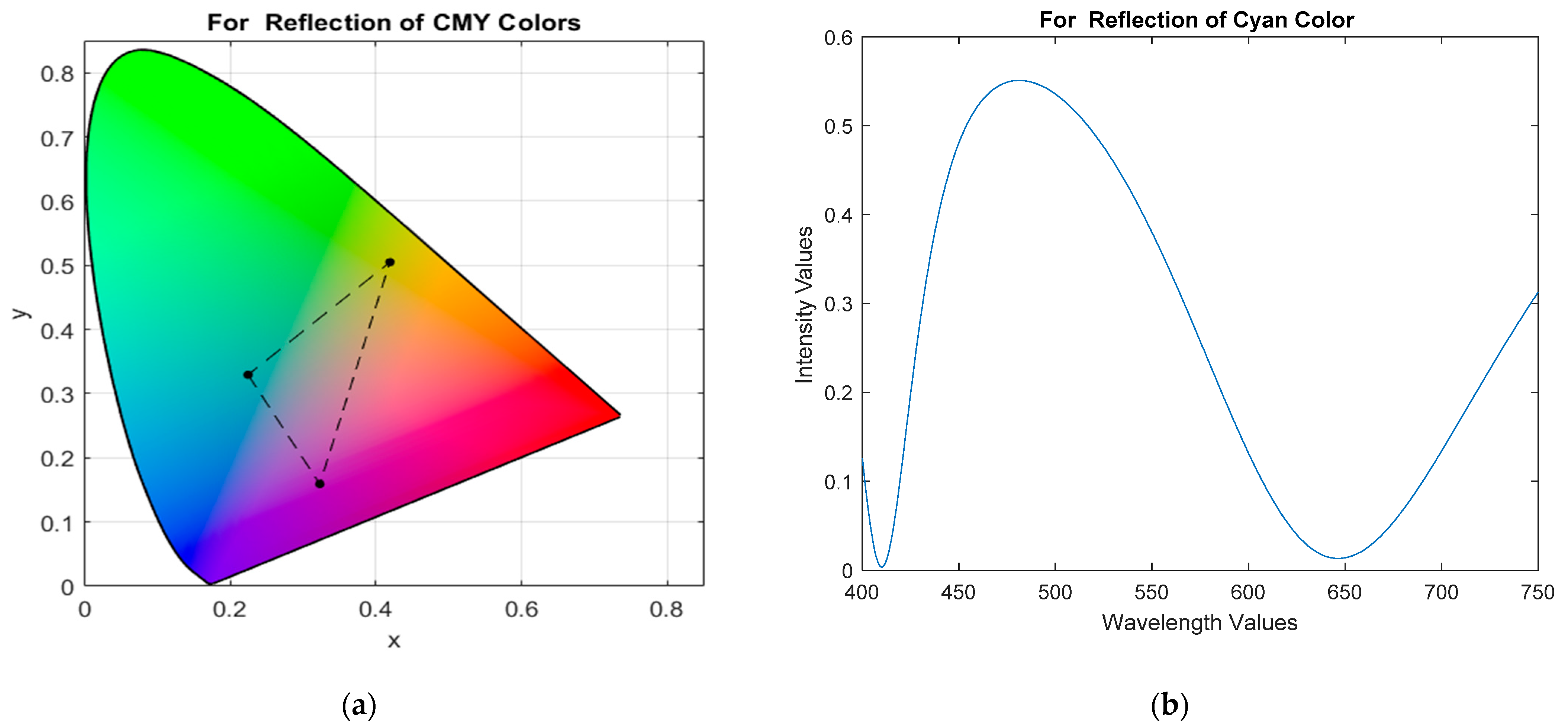
This section covers the filter design parameters and simulation results. The purity of the three filtered reflected colors—magenta, yellow, and cyan–as well as the efficiency of each filtered reflected color rely on the optimal layer thickness, as indicated in Table 3. The color coordinate values for cyan, magenta, and yellow that were obtained using the reflective color filters are shown in Figure 3 on the CIE 1931 plot. These reflected colors are depicted by a color triangle on the CIE plot in Figure 3.
R D = ( E x F x ) 2 + ( E y F y ) 2
Using the coordinate values for the cyan, yellow, and magenta colors from Table 2 and Table 4 in Equation (21), the color purity value and relative distance value is 0.0014 for magenta, 0.004 for cyan, and 0.021 for yellow. From Figure 3b the cyan color intensity values are approximately 55%, while in Figure 3c,d, magenta has a 35% intensity value and yellow has 50%.

4. Conclusions

The proposed reflective CMY filter design presented in the study outperformed other existing designs, as demonstrated in Table 5 by the color purity values obtained using the coordinate values for cyan, yellow, and magenta colors. The filter design is efficient in producing pure cyan, magenta, and yellow as reflected colors, which could result in better-quality light signal transmission and reception through fiber optic communication. One important observation made during the design process was that the color intensity values change significantly with an increase in the thickness of the dielectric layers. Low-intensity values are expected with a relatively thicker layer. Filter layers should be fabricated under the 150 nm structure of thin films used.

Author Contributions

Conceptualization, S.H.M. and S.M.; methodology, S.H.M.; software, M.A.P.D.; validation, S.H.M., S.M. and M.A.P.D.; formal analysis, S.H.M.; investigation, S.M.; resources, S.H.M.; data curation, S.H.M.; writing—original draft preparation, S.H.M.; writing—review and editing, S.H.M.; visualization, S.M.; supervision, S.H.M.; project administration, S.H.M.; funding acquisition, S.H.M. All authors have read and agreed to the published version of the manuscript.

Funding

This research received no external funding.

Institutional Review Board Statement

Not applicable.

Informed Consent Statement

Not applicable.

Data Availability Statement

Not applicable.

Conflicts of Interest

The authors declare no conflict of interest.

References

  1. Idachaba, F.; Ike, D.U.; Hope, O. Future Trends in Fiber Optics Communication. In Proceedings of the World Congress on Engineering 2014, London, UK, 2–4 July 2014; pp. 438–442. [Google Scholar]
  2. Jansen, S.L.; van den Borne, D.; Spinnler, B.; Calabro, S.; Suche, H.; Krummrich, P.; Sohler, W.; Khoe, G.-D.; de Waardt, H. Optical phase conjugation for ultra long-haul phase-shift-keyed transmission. J. Light. Technol. 2006, 24, 54–64. [Google Scholar] [CrossRef]
  3. Oliveira, J.; Magalhães, E.; Januário, J.; Siqueira, M.; Scaraficci, R.; Salvador, M.; Mariote, L.; Guerrero, N.; Carvalho, L.; Hooft, F.V.; et al. Toward Terabit Autonomic Optical Networks Based on a Software Defined Adaptive/Cognitive Approach [Invited]. J. Opt. Commun. Netw. 2015, 7, A421–A431. [Google Scholar] [CrossRef]
  4. Munguía, J.; Ciurana, J.; Riba, C. Neural-network-based model for build-time estimation in selective laser sintering. Proc. Inst. Mech. Eng. Part B J. Eng. Manuf. 2009, 223, 995–1003. [Google Scholar] [CrossRef]
  5. Gu, R.; Yang, Z.; Ji, Y. Machine learning for intelligent optical networks: A comprehensive survey. J. Netw. Comput. Appl. 2020, 157, 102576. [Google Scholar] [CrossRef]
  6. Kim, I.; So, S.; Rana, A.S.; Mehmood, M.Q.; Rho, J. Thermally robust ring-shaped chromium perfect absorber of visible light. Nanophotonics 2018, 7, 1827–1833. [Google Scholar] [CrossRef]
  7. Rana, A.S.; Zubair, M.; Anwar, M.S.; Saleem, M.; Mehmood, M.Q. Engineering the absorption spectra of thin film multilayer absorbers for enhanced color purity in CMY color filters. Opt. Mater. Express 2020, 10, 268. [Google Scholar] [CrossRef]
  8. Rana, A.S.; Zubair, M.; Danner, A.; Mehmood, M.Q. Revisiting tantalum based nanostructures for efficient harvesting of solar radiation in STPV systems. Nano Energy 2021, 80, 105520. [Google Scholar] [CrossRef]
  9. Rana, A.S.; Nasir, M.; Khan, H.A. String level optimisation on grid-tied solar PV systems to reduce partial shading loss. IET Renew. Power Gener. 2018, 12, 143–148. [Google Scholar] [CrossRef]
  10. Koirala, I.; Lee, S.-S.; Choi, D.-Y. Highly transmissive subtractive color filters based on an all-dielectric meta surface incorporating TiO2 nanopillars. Opt. Express 2018, 26, 18320–18330. [Google Scholar] [CrossRef]
  11. Lee, K.-T.; Seo, S.; Guo, L.J. High-Color-Purity Subtractive Color Filters with a Wide Viewing Angle Based on Plasmonic Perfect Absorbers. Adv. Opt. Mater. 2015, 3, 347–352. [Google Scholar] [CrossRef]
  12. Sadatnajafi, C.; Balaur, E.; Abbey, B. Bimodal Plasmonic Color Filters Enable Direct Optical Imaging of Ion Implantation in Thin Films. Adv. Funct. Mater. 2022, 32, 2009419. [Google Scholar] [CrossRef]
  13. Rana, A.S.; Mehmood, M.Q.; Jeong, H.; Kim, I.; Rho, J. Tungsten-based Ultrathin Absorber for Visible Regime. Sci. Rep. 2018, 8, 2443. [Google Scholar] [CrossRef] [PubMed]
  14. Park, C.-S.; Shrestha, V.R.; Lee, S.-S.; Kim, E.-S.; Choi, D.-Y. Omnidirectional color filters capitalizing on a nano-resonator of Ag-TiO2-Ag integrated with a phase compensating dielectric overlay. Sci. Rep. 2015, 5, 8467. [Google Scholar] [CrossRef] [PubMed]
  15. Park, C.-S.; Shrestha, V.R.; Lee, S.-S.; Choi, D.-Y. Trans-Reflective Color Filters Based on a Phase Compensated Etalon Enabling Adjustable Color Saturation. Sci. Rep. 2016, 6, 25496. [Google Scholar] [CrossRef]
  16. Naeem, T.; Rana, A.S.; Zubair, M.; Tauqeer, T.; Mehmood, M.Q. Breaking planar symmetries by a single layered metasurface for realizing unique on-chip chiroptical effects. Opt. Mater. Express 2020, 10, 3342–3352. [Google Scholar] [CrossRef]
  17. Kim, J.; Rana, A.S.; Kim, Y.; Kim, I.; Badloe, T.; Zubair, M.; Mehmood, M.Q.; Rho, J. Chiroptical Meta surfaces: Principles, Classification, and Applications. Sensors 2021, 21, 4381. [Google Scholar] [CrossRef]
  18. Shrestha, V.R.; Lee, S.-S.; Kim, E.-S.; Choi, D.-Y. Polarization-tuned Dynamic Color Filters Incorporating a Dielectric-loaded Aluminum Nanowire Array. Sci. Rep. 2015, 5, 12450. [Google Scholar] [CrossRef]
  19. Li, Z.; Butun, S.; Aydin, K. Large-Area, Lithography-Free Super Absorbers and Color Filters at Visible Frequencies Using Ultrathin Metallic Films. ACS Photonics 2015, 2, 183–188. [Google Scholar] [CrossRef]
  20. Shrestha, V.R.; Lee, S.-S.; Kim, E.-S.; Choi, D.-Y. Aluminum Plasmonics Based Highly Transmissive Polarization-Independent Subtractive Color Filters Exploiting a Nanopatch Array. Nano Lett. 2014, 14, 6672–6678. [Google Scholar] [CrossRef]
  21. Cheng, F.; Gao, J.; Luk, T.S.; Yang, X. Structural color printing based on plasmonic meta surfaces of perfect light absorption. Sci. Rep. 2015, 5, 11045. [Google Scholar] [CrossRef]
  22. Kats, M.A.; Blanchard, R.; Genevet, P.; Capasso, F. Nanometre optical coatings based on strong interference effects in highly absorbing media. Nat. Mater. 2013, 12, 20–24. [Google Scholar] [CrossRef] [PubMed]
  23. Shrestha, V.R.; Lee, S.-S.; Kim, E.-S.; Choi, D.-Y. Non-iridescent Transmissive Structural Color Filter Featuring Highly Efficient Transmission and High Excitation Purity. Sci. Rep. 2014, 4, 4921. [Google Scholar] [CrossRef] [PubMed]
  24. Lin, J.; Luo, S.; Zuo, D.; Wang, X. Multilayer structure for highly transmissive angle-tolerant color filter. Opt. Commun. 2018, 427, 158–162. [Google Scholar] [CrossRef]
  25. Yang, C.; Shen, W.; Zhang, Y.; Peng, H.; Zhang, X.; Liu, X. Design and simulation of omnidirectional reflective color filters based on metal-dielectric-metal structure. Opt. Express 2014, 22, 11384–11391. [Google Scholar] [CrossRef] [PubMed]
Figure 1. Flow chart of opto-electronic reflective CMY color filters design process.
Engproc 32 00001 g001
Figure 2. (a) Design schematics of a tri-layer-based opto-electronic reflective (CMY) color filter; (b) description of how light interacts with incident light from air in proposed tri-layer filter design.
Engproc 32 00001 g002
Figure 3. (a) Obtained pure CMY color triangle on CIE 1931 plot; (b) Output wave graph for reflected cyan color from proposed filter; (c) Output wave graph for reflected magenta color from proposed filter; and (d) Output wave graph for reflected yellow color from proposed filter.
Engproc 32 00001 g003aEngproc 32 00001 g003b
Table 1. Design details of the tri-layer reflective color filter.
Materials Placement Name Refractive Index Value (mo)Material NatureThickness Notation (nm)
1st layerTitanium dioxide2.6Dielectric J1
2nd layerSilicon3.9Semiconductor J2
3rd layerTitanium dioxide1.4DielectricJ3
Table 2. CIE 1931 standard CMY color coordinate values.
Reflective Colorsx-Axis (Ex)y-Axis (Ey)
Cyan0.2240.328
Yellow0.4190.505
Magenta0.3200.154
Table 3. Layer thickness for efficient opto-electronic CMY color filters for fiber optic communication.
MaterialsLayer Thickness (nm) for Magenta Color Layer Thickness (nm) for Cyan ColorLayer Thickness (nm) for Yellow Color
Titanium dioxide (J1)42.642.8147.1
Silicon (J2)8.0674.288.1
Silicon dioxide (J3)119.322.549.4
Table 4. Tri-layer reflective color filter design CMY output color coordinate values.
Reflective Colorsx-Axis (Fx)y-Axis (Fy)
Cyan0.2200.328
Yellow0.4120.485
Magenta0.3210.153
Table 5. Comparison of color purity/relative distance values of Tri-layer reflective CMY color filters with previous studies.
Previous WorksMagenta Color (x,y)Relative Distance (RD)Proposed Tri-Layer Design (RD) Value (0.0014)Cyan Color (x,y)Relative Distance (RD)Proposed Tri-Layer Design (RD) Value (0.004)Yellow Color (x,y)Relative Distance (RD)Proposed Tri-Layer Design (RD) Value (0.021)
[21]
Meta materials
(0.38,0.27)0.1399Improved(0.26,0.36)0.0558Improved(0.42,0.42) 0.0759Improved
[19]
Multi-layer
(0.21,0.54)0.2197Improved
[7]
Multi-layer
(0.32,0.16)0.0116Improved(0.22,0.27)0.0578Improved(0.46,0.44)0.0758Improved
[25]
Meta materials
(0.32,0.16)0.0116Improved(0.22,0.27)0.0578Improved(0.46,0.46)0.0758Improved
Disclaimer/Publisher’s Note: The statements, opinions and data contained in all publications are solely those of the individual author(s) and contributor(s) and not of MDPI and/or the editor(s). MDPI and/or the editor(s) disclaim responsibility for any injury to people or property resulting from any ideas, methods, instructions or products referred to in the content.