Proceeding Paper

Novel Strain Sensor in Weft-Knitted Textile for Triggering of Functional Electrical Stimulation †

1
Institute for Textile Machinery and High Performance Material Technology (ITM), Faculty for Mechanical Science and Engineering, Technische Universität Dresden, 01069 Dresden, Germany
2
CeTI—Cluster of Excellence, Centre for Tactile Internet with Human-in-the-Loop, Technische Universität Dresden, 01069 Dresden, Germany
*
Author to whom correspondence should be addressed.
Presented at the 4th International Conference on the Challenges, Opportunities, Innovations and Applications in Electronic Textiles, Nottingham, UK, 8–10 November 2022.
Eng. Proc. 2023, 30(1), 13; https://doi.org/10.3390/engproc2023030013
Published: 31 January 2023

Abstract

:
Functional electrical stimulation (FES) aims to improve the gait pattern in case of foot drop of people suffering chronic diseases, e.g., multiple sclerosis. The fibular nerve can be stimulated by electrical impulses sent through electrodes on the skin, which leads to the contraction of the corresponding muscles. One major disadvantage of commercial FES devices is their bulky design. The paper presents an alternative approach of weft-knitted strain sensors that are directly integrated into the knee area of a functional legging suitable for daily use. To initiate electrical impulses for FES at the right time, the textile strain sensors are used as soft triggers.

1. Introduction

Wearables have developed very rapidly over the last decade and have become integral parts of our daily lives. Due to their convenience and flexibility, they are used for gesture and posture tracking in healthcare and biomechanical and physiological monitoring systems [1]. An important functional therapy method for multiple sclerosis (MS) related foot drop or stroke patients is functional electrical stimulation (FES), in which the muscle is functionally activated by electrical nerve stimulation and can thus perform its physiological movement [2]. Neuro-prostheses are one of the advances that have been made in the field of FES therapy. They detect the gait phases through inertial measurement units (IMU), which then trigger electrical impulses to stimulate the corresponding nerve at the appropriate moment so that the foot rises [3,4]. Commercially available assistance systems for people with foot-lift weakness are, e.g., L100/300 Go® [5,6] from Bioness, innoSTEP-WL [7] from Heller Medizintechnik, or WalkAide® from Pro Walk [8]. In these bulky devices, the sensors and electrical signal generator are integrated directly into a cuff that is fixed with Velcro straps around the knee. However, the size and mass, the built-in hard electronics (inflexible, non-bendable areas), and the limited washability are comfort-limiting factors of these devices for daily use. Therefore, the aim of the current research at ITM is the realization of a textile-based sensory and therapeutic stimulative functional system integrated into a weft-knitted fabric in the form of functional leggings.
Electrically conductive yarns are suitable for the realization of resistive strain sensors, whose electrical resistance changes in correlation to the applied mechanical strain and can be integrated into a weft-knitted fabric during manufacturing. In addition to that, the joint movement according to the natural degrees of freedom that causes a corresponding strain state in the textile can also be measured. Due to the loop structure, knitted fabrics are stretchable in both horizontal and vertical directions, resulting in a low bending modulus and shear. The user comfort of weft-knitted fabrics in terms of freedom of movement make them a suitable choice for use as supporting structures of wearable healthcare products [9], e.g., for both future textile-based strain sensors and dry electrodes for FES therapy purposes, respectively. Due to the loop structure, weft-knitted fabrics are also characterized by excellent permeability and flexibility. The gait analysis for FES devices requires a real-time diagnostic function to determine the movements based on the deformation measurement, for which integrated textile strain sensors are predestined. The textile-based strain sensor is positioned on the kneecap and is intended to determine valid motion-induced strain data without restricting the freedom of movement of the functional leggings. The textile structure is stretched accordingly by the bending movement of the leg during the gait phase, and the measurable change in ohmic resistance can be correlated with the movement phase. Based on previous investigations using weft-knitted structures, the maximum expected elongation in the knee area is determined to a max of 50%.

2. Materials and Methods

For the gait analyses, suitable conductive yarn-based resistive strain sensors on the knee area are needed. Based on investigations using weft-knitted structures, the maximum expected elongation in the knee area is determined to the max of 50%. It is essential that the textile sensor is flexible and does not restrict free movement. With dynamic movement, the knee or bent angle changes continuously. Bending is defined here as the direction of motion, which leads to the reduction of angle and stretching, causing an increase of the angle. To determine the expected length change of the weft-knitted structure (leggings) above the kneecap, the knee is bent in 45° steps from the unbent to full-bent state and the lengths L1 to L4 are measured. Based on the observations, the expected elongation of weft-knitted structures over the knee joint during walking is determined at a range from 23 to 50%. This represents the measuring range of the textile strain sensor (cf. Table 1). Although other gait analyses come to similar conclusions that the bending/flexion of the knee joint during normal walking reaches max. 60° (max. elongation/extension 0°), for the further development steps [10,11], a maximum elongation of 30% is assumed as the average deformation to be expected during the normal gait phase.
Weft-knitted strain sensors are realized on a conventional weft-knitting machine (Karl Mayer Stoll ADF 530-32 BW knit & wear, E14 machine gauge) available at ITM. The basic knit structures have been developed, and material combinations were evaluated. The investigations were based on a plated, plain, right−left weft-knitted structure (single jersey) made of a material combination from TENCEL™ lyocell fibers (fineness 25 tex) plated with a polyamide and elastane twine PA/EL 78/78f23x1. The strain sensors are integrated into four different bindings in wale-wise (A, B) and course-wise directions (C, B). The strain-sensor pattern was realized by intarsia knitting or platting, respectively, using different silver coated/plated conductive yarns Silver-tech+ 150, Elitex 235/f36 PA/Ag. Table 2 shows the investigated materials and bindings of the weft-knitted basic structure and the textile-based sensors.
For characterization of the strain sensor’s cyclical tensile behavior, specimens (cf. Table 2) were tested on a ZwickRoell Junior Z2.5 tensile tester. The tensile strain is increased from 0 to 50% successive in 10% steps after 10 cycles while measuring the change in resistance of the textile-based strain sensors simultaneously with a Keithley DAQ 6510 precision multimeter in a 4-wire method.

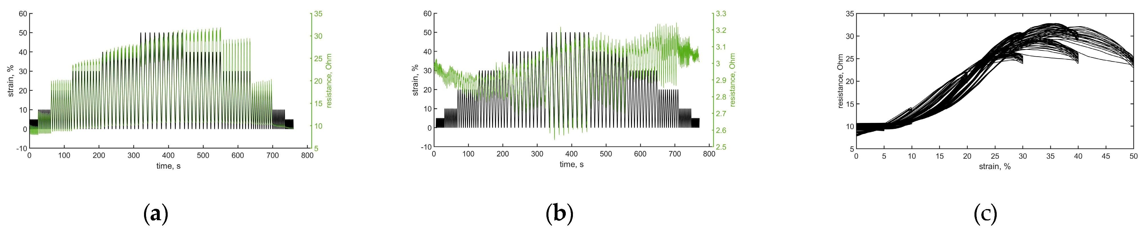
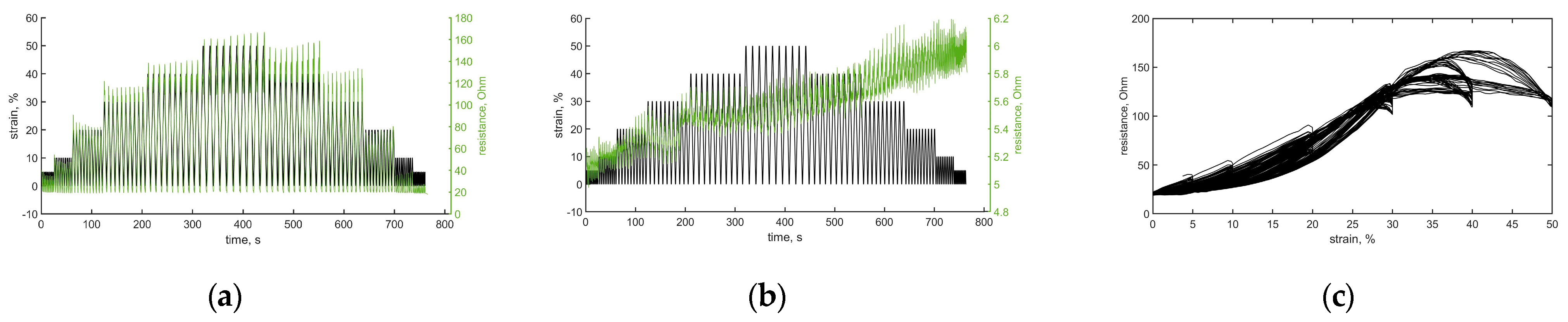
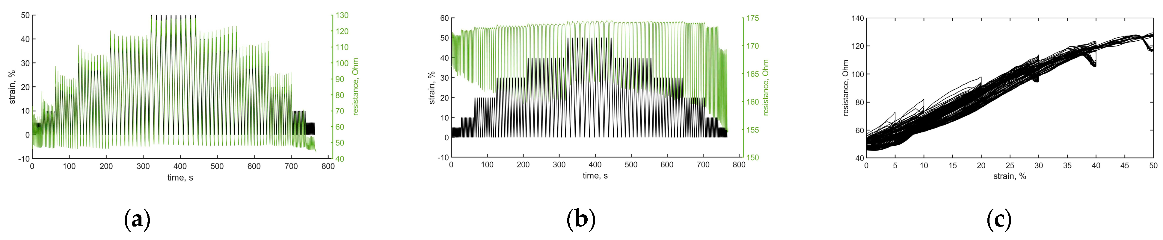
3. Results and Discussion

As observed in Figure 1a, the sensor binding A with yarn I has a good correlation between change in strain and resistance compared with sensor C (cf. Figure 1b) with the same yarn (cf. Figure 1b). The hysteresis increases for strain levels above 25% significantly, as Figure 1c shows, and the cross-correlation coefficient was calculated to 0.83. Furthermore, a latent signal drift after each load cycle within a constant elongation level can be observed.
Figure 2 shows that sensor binding A with yarn II also has a good correlation between the change in resistance and applied strain with a cross-correlation coefficient 0.94 (cf. Figure 1c). For sensor binding C (cf. Figure 2b), which means the course-wise integration of the sensor yarn in a single wale over 100 courses, the resistance-strain correlation is remarkably low.
Figure 3 shows that the sensor binding B with yarn I (cf. Figure 3a,c) has the best correlation between strain and resistance. The cross-correlation coefficient was calculated to 0.99. For all investigated sensor yarns, sensor bindings C and D (cf. Figure 3b) show the lowest resistance-strain correlation of the investigated test series. It can be stated that the course-wise platting of conductive yarns is not suitable for reliable strain sensing.

4. Conclusions

This work presents a novel approach for the integration of conductive yarns into weft-knitted fabric acting as strain sensor for monitoring and detecting the gait phase for FES applications, e.g., for patients suffering from MS. Two conductive yarns in wale-wise and course-wise directions have been integrated into a plated plain right-left weft-knitted structure, and the electromechanical behavior was determined during cyclical tensile tests. It can be concluded that the strain sensor made of silver-coated yarn Silver-tech+ 150 plated with PA/EL elastane twine in a plain right/left wale-wise binding structure B (1 wale × 200 courses) shows the best result concerning a change of resistance under an applied cyclic tensile strain up to 30% with cross-correlation coefficient calculated to 0.99.

Author Contributions

Conceptualization, B.A., H.W., and E.H.; methodology, B.A. and M.W.; software, M.W.; knitting design, knitting, specimen preparation, C.S.; validation, E.H., A.N., and M.W.; formal analysis, M.W.; investigation, B.A. and H.W.; resources, B.A.; data curation, M.W.; writing—original draft preparation, B.A.; writing—review and editing, E.H.; visualization, B.A.; supervision, E.H.; project administration, C.C.; funding acquisition, E.H. All authors have read and agreed to the published version of the manuscript.

Funding

The project is funded by the German Research Foundation (DFG. Deutsche Forschungsge meinschaft) as part of Germany’s Excellence Strategy—EXC 2050/1—funding Nr. 390696704—Cluster of Excellence “Centre for Tactile Internet with Human-in-the-Loop” (CeTI) of Technische Universität Dresden. The ZIM project “SmartMediTex”, funding Nr. KK5090906SK1, is funded through the AiF within the “Central Innovation Program for small and medium-sized enterprises (SMEs)—Zentrales Innovationsprogramm Mittelstand (ZIM)—Cooperation projects” from funds of the Federal Ministry for Economic Affairs and Climatic Action (BMWK) by a resolution of the German Bundestag. Funding of the named institutions is gratefully acknowledged.

Institutional Review Board Statement

Not applicable.

Informed Consent Statement

Not applicable.

Data Availability Statement

All data are available from authors by request.

Conflicts of Interest

The authors declare no conflict of interest.

References

  1. Isaia, C.; Mcnally, D.S.; Mcmaster, S.A.; Branson, D.T. Effect of mechanical preconditioning on the electrical properties of knitted conductive textiles during cyclic loading. Text. Res. J. 2019, 89, 445–460. [Google Scholar] [CrossRef]
  2. Miller, L.; Mattison, P.; Paul, L.; Wood, L. The effects of transcutaneous electrical nerve stimulation (TENS) on spasticity in multiple sclerosis. Mult. Scler. 2007, 13, 527–533. [Google Scholar] [CrossRef] [PubMed]
  3. Gorman, P.H. An Update on Functional Electrical Stimulation after Spinal Cord Injury. Neurorehabilit. Neural Repair 2000, 14, 251–263. [Google Scholar] [CrossRef] [PubMed]
  4. Creasey, G.H.; Ho, C.H.; Triolo, R.J.; Gater, D.R.; DiMarco, A.F.; Bogie, K.M.; Keith, M.W. Clinical applications of electrical stimulation after spinal cord injury. J. Spinal Cord Med. 2004, 27, 365–375. [Google Scholar] [CrossRef] [PubMed]
  5. Hausdorff, J.M.; Ring, H. The effect of the L300 neuroprosthesis on gait stability and symmetry. J. Neurol. Phys. Ther. 2006, 30, 198–199. [Google Scholar] [CrossRef]
  6. Improved Mobility. Made Easier. Bioness Inc., NC 27703, United States: 2022. Available online: https://www.l300go.com/ (accessed on 21 November 2022).
  7. HELLER MEDIZINTECHNIK GmbH & Co. KG: Weak Foot Dorsi Flexion—Foot Drop System innoSTEP-WL Provides Mobility. Available online: https://www.heller-medizintechnik.de/produkte/innostep_wl/?lang=EN (accessed on 12 November 2022).
  8. Pro Walk Rehabilitationshilfen und Sanitätsbedarf GmbH: The WalkAide®—System. Myo-Orthetic Technology for the Treatment of Centrally Caused Foot Lift Weakness. Available online: https://www.prowalk.de/produkte/walkaide/ (accessed on 20 November 2022).
  9. Euler, L.; Guo, L.; Persson, N.-K. Textile Electrodes: Influence of Knitting Construction and Pressure on the Contact Impedance. Sensors 2021, 21, 1578. [Google Scholar] [CrossRef] [PubMed]
  10. Watson, A.; Sun, M.; Pendyal, S.; Zhou, G. TracKnee: Knee angle measurement using stretchable conductive fabric sensors. Smart Health 2020, 15, S.100092f. [Google Scholar] [CrossRef]
  11. Götz-Neumann, K. Understanding Walking—Gait Analysis in Physiotherapy, 4th ed.; Thieme; Georg Thieme Verlag: Stuttgart, Germany, 2016; ISBN 9783132401549. [Google Scholar]
Figure 1. Electromechanical behavior of sensor yarn I during cyclic straining: (a) change in resistance with binding A; (b) change of resistance with binding C; (c) resistance-strain correlation for binding A.
Engproc 30 00013 g001
Figure 2. Electromechanical behavior of sensor yarn II during cyclic straining: (a) change in resistance with binding A; (b) change of resistance with binding C; (c) resistance−strain correlation for binding A.
Engproc 30 00013 g002
Figure 3. Electromechanical behavior of sensor yarn I during cyclic straining: (a) change in resistance with binding B; (b) change of resistance with binding D. (c) resistance−strain correlation for binding B.
Engproc 30 00013 g003
Table 1. Determined elongation of a weft-knitted structure fixed over knee joint during leg angulation.
Leg Position, Bent AngleLength Knit Structure Li [cm]Expected Strain
εm = Li-Li-1/Li-1 [%]
Basic lengthL09.2-
Pre-stretched, unbent 0°L11223
Bent by 45°L215.126
Bent by 90°L316.336
Full bent (140°)L41850
Table 2. Overview materials and bindings of basic weft-knitted structure and textile sensors.
Sensor Yarns (Red Area)Binding Basic Knit and Material
(Yellow Area)
Sensor Binding
I: Silver-tech+ (Silver coated pol- yamide yarn; 150 tex)
II: Elitex 235/f36 (Silver coated pol- yamide yarn)
Plated right left single jersey
Tencel 25 tex plated with PA/EL single cover yarn 78/78f23x1
Engproc 30 00013 i001Wale-wise plating of sensor yarns
A: 4 wales × 200 courses
B: 1 wale × 200 courses
course-wise plating of sensor
yarns
C: 100 wales × 4 courses
D: 100 wales × 1 course
Disclaimer/Publisher’s Note: The statements, opinions and data contained in all publications are solely those of the individual author(s) and contributor(s) and not of MDPI and/or the editor(s). MDPI and/or the editor(s) disclaim responsibility for any injury to people or property resulting from any ideas, methods, instructions or products referred to in the content.

