1. Introduction
Operational monitoring of complex gas mixtures (CGM) of various origins in order to quickly track the transformation of an “acceptable” situation into a potentially “dangerous” one is a necessary condition for ensuring the safety of the civilian population and timely prevention (if possible) or the most effective response to said situation, in order to effectively overcome negative consequences. Within the framework of an ever-faster developing technological civilization, this general problem is directly related to the determination of potentially dangerous atmospheric gases when monitoring the environmental situation, the timely detection of allergenic components, the control of working area air in enterprises, compliance with the regulation of technological processes, etc. The solution forsuch a diverse type of tasks involves the development of, in a sense, “universal” devices that simultaneously have the properties of mobility and autonomy, while providing the ability to detect “changing conditions of the reference environment”, process “states’ fingerprints” and generate “alarm signals” within asingle set ofequipment.
The variety of tasks that are set for such systems determine the specific nature of the requirements in relation to the registration unit of gaseous components. For the purposes of monitoring the status of a complex gas mixtures, it is not necessary to have information about their composition, but only that it remains unchanged (or changes in a given range of values of given criteria). This approach fully reflects the concept of electronic nose technologies [
1,
2], whereina multisensor array is developed with a wide range of sensitivity to the maximum possible number of different compounds using weakly selective sensors with pronounced crossselectivity.
It is obvious that no matter what unique capabilities a sensing system possesses, it is practically impossible to provide effective control of the perimeter of a potentially dangerous gas zone of a large area using only one device. In this case, it is necessary to form a network of intelligent devices (distributed alarm networks) that interact with each other and decide together the task assigned to them. Such a system typically comprises at least two devices: (i) a registration unit that detects and processes alarm conditions and that is immersed in the atmosphere of interest, and (ii) a remote device (central station) that generates alarms signals that may or may not be in the vicinity of the detection units. In this case, a two-way wireless communication system can generate alarm signals for alarm conditions forthe responsible operator in an area far removed from the monitoring devices. Such distributed systems may be of particular interest for monitoring objects of increased danger (for example, in the chemical and pharmaceutical industries, power plants, etc.), wherealmost any significant difference in the gas composition of the atmospherefrom the “reference” state may indicate a potentially dangerous situation for humans and the environment.
The main purpose of this article is to describe the design and construction of a distributed remote-controlled sensor network that provides monitoring of the status of complex gas mixtures in terms of Gestalt-like perception by their virtual coding with so-called chemical images. This is necessary, in particular, to ensure compliance with the requirements of existing safety standards with respect tothe atmosphere, which makes it possible to prevent a potentially dangerous development of the situation. This paper considers the concept of the electronic part of a distributed monitoring system based on commercially available elements and systems of microsystem technology.
2. Conceptualization and Motivation
Ashort overview of state-of-the-art in profiling technologies enables us to conclude that the application of traditional methods based on a “univariate” sensor array with a hard-coded list of selective sensors forthe monitoring of complex gas mixtures often runs into problems [
3,
4,
5,
6]. This results from the fact that multicomponent chemical media contain abundant quantities of fractions differing in their chemical and physical nature. To obtain information about such samples with numerous and unknown components using traditional techniques encountersboth fundamental and technical restrictions. Moreover, this molecular level information must be presented in a form that can be processed by the human user since the evaluation process depends on results derived by the analysis and interpretation of collected data.
The complex mixtures can be described not asa sum of their individual components but by some abstract representation—a chemical image (CI)—a virtual fingerprint with a set of intrinsic parameters for a given CGM. An array of low-selective/cross-reactive sensors (“multivariate” sensing systems) can be used to form a CI of a CGM with further classification and identification based on the image recognition techniques. The sensors’ responses have to represent the result of the interaction between the CGM components and a sensitive layer with desired chemical functionality: arrays of sensors mapping the CGM variety in the chemical space onto the m-dimensional response space (m is the number of sensors). Thus, when used with complex mixtures, analysis methods are intended to identify the set of features (which are linear or nonlinear combinations of response characteristics) that can segregate identifiable CGM; in this way, they are similar to data processing algorithms commonly used when evaluating expression arrays in electronic nose technology [
7,
8,
9,
10].
The actual challenge is to extend the using the “multivariate” sensing array in safety evaluation tools based on distribution sensor networks. The main focus of this article is on developing a prototype of registration and communication modules for distributed fingerprint technology based on “multivariate” cross-reactive arrays that aim to highlight the overall trends in complex gaseous media. To elaborate: new hardware for “multivariate” arrays will be desired, in which low-selective sensors are used to analyze the levels of different components and this complex information iscorrelated with specific fingerprints—“virtual markers” of the CGM status—by pattern recognition methods. More information regarding cross-reactive sensor array can be found in [
11,
12,
13,
14,
15,
16,
17,
18,
19,
20].
The main idea of the system design is to use remotely controlled arrays of adaptive chemical sensors (based on e-nose technology) as registration units in combination with intelligent analysis systems (specific coding and their follow-up classification by pattern recognition) and public telecommunication networks for information exchange. This makes it possible to develop a distributed and fairly universal monitoring system for complex gaseous media, which provides formalization of their status and identification of changes in them associated with potential hazards for humans and the environment over long periods of time.
3. Prototype Design and Construction
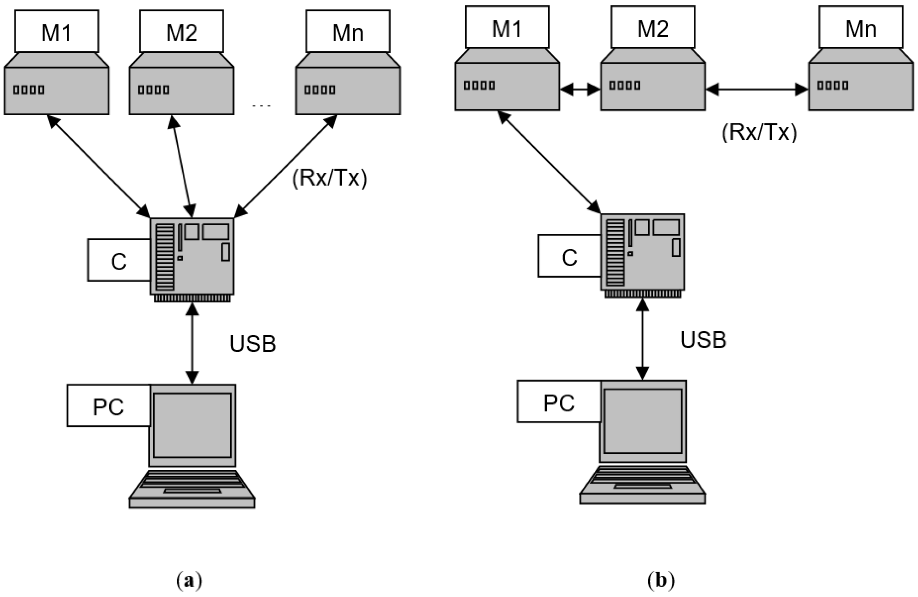
To ensure monitoring of CGM in accordance with the required standards, it is advisable to use distributed automated systems for monitoring the gaseous environment in real time. In the framework of this work, we consider a distributed network of discrete modules, which consists of two types of devices—sensor (registration) modules and a central station, which can be integrated into the GSM network or connected to the global Internet space. The main components of such systems are (
Figure 1): (1) a central station with an expert decision-making system that controls and monitors the performance of the entire system, (2) several remote arrays of sensors powered by (3) a local power supply unit with (4) a block for transmitting and receiving information between the modules and the central station using (5) the corresponding initial coding of the state of the external gaseous medium and information protocols for the transmission of information.
The principle of operation of the registration unit for measuring the components of a gas mixture is based on a change in the frequency of vibrations of a quartz plate (physical transducer) with a change in the amount of substance on its surface—quartz crystal microbalance (QCM). The measuring element of such a system is quartz plates with metal electrodes and various absorbent layers deposited on these electrodes (sensitive layers). Absorption by this layer of a substance from the analyzed gas mixture leads to an increase in the mass mechanically associated with the surface of a quartz plate, and a decrease in the natural frequency of oscillations of such a plate. The absorption process can be reversible, resulting in a decrease in the mass associated with the surface and an increase in the oscillation frequency. Since the quartz plate has a high quality factor, this ensures the stabilization of the frequency of the oscillator, for which such a plate with a sensitive layer will set the frequency of its resonant oscillations. The frequency at the output of such a generator will correspond to the oscillation frequency of a quartz plate, and will accordingly change with a change in the amount of a substance mechanically bound to the surface. For such a system, a change in frequency is an information signal that is directly related to the amount of substance that is on their surface.
In accordance with the chosen physical principle of registration of the molecular components of the gas mixture, the measuring part of the device consists of a measuring unit, which contains sensor elements with a unit of generators that form an output signal in the form of a meander with a frequency equal to the natural frequency of vibrations of a quartz plate with a sensitive layer and a recording module. The registration module also provides pulse counting and frequency determination, as well as synchronization of the command and data flow between the device and the central station.
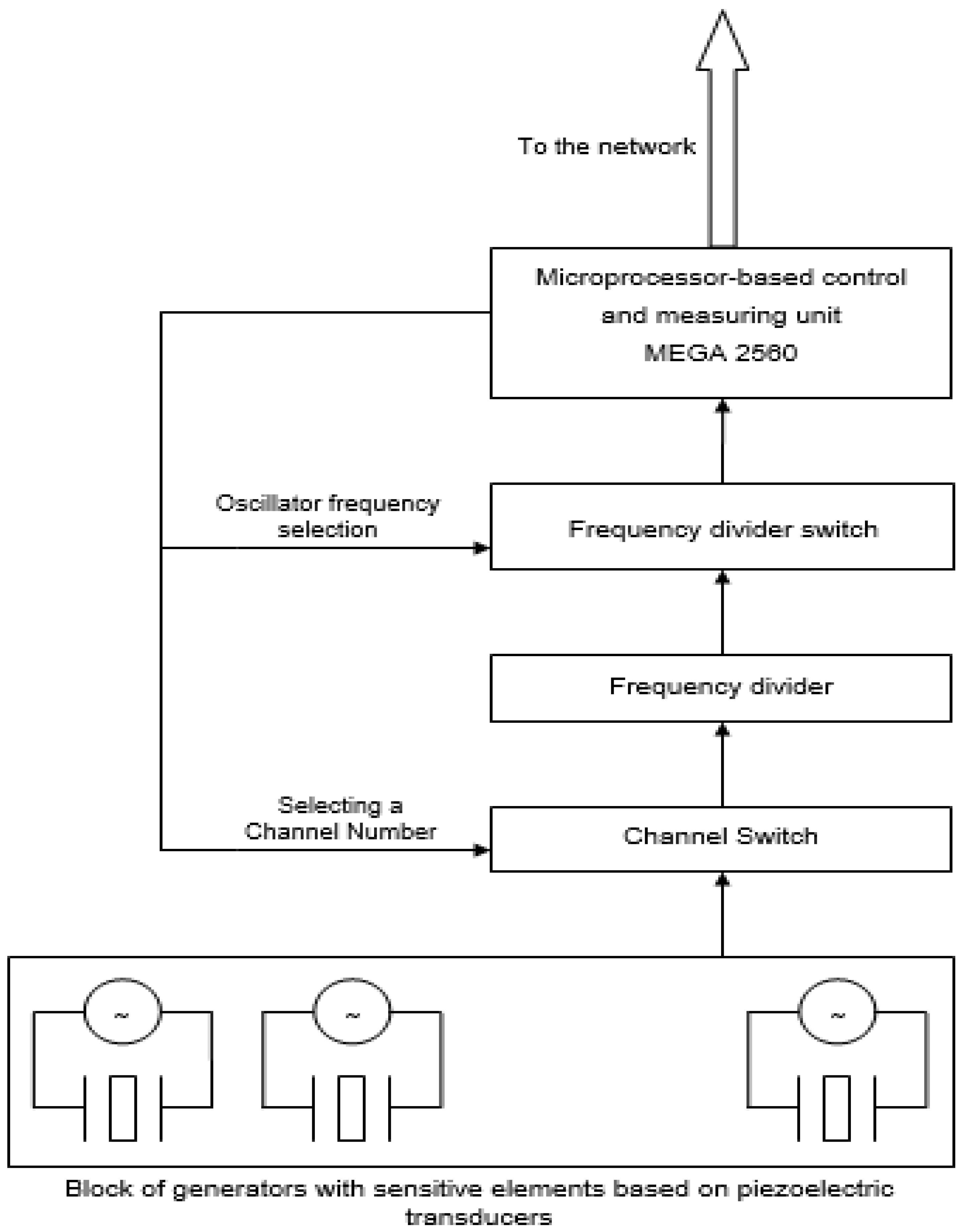
The block diagram of the registration module is shown in
Figure 2. The measuring unit is a modular construction using commercially available Arduino hardware and software for building and prototyping microprocessor devices. A MEGA 2560 processor module is used as a basic control device. The device control firmware is stored in the FLASH memory of the microcontroller: this controls the state of the entire device, ensures synchronization of the exchange of commands and data through the Rx/Tx protocol with the central station and other registration unit, and also controls the operation of the counter and channel switch.
The principle of operation of the system is based on the definition of the concept of frequency. That is, the system directly counts the number of vibrations of a quartz plate that occur within one second. In the frequency registration module, this is implemented as follows. Having received a command from the control computer to measure the frequency, the microcontroller, the speed of which is set by the reference oscillator, sends a reset signal to the counter, setting it to zero. Then it sends a signal to enable the account. The output values increase by one with each new pulse of the crystal oscillators of the oscillator module. After passing a predetermined time interval (1 sec), counted by the reference oscillator, the microcontroller removes the “counting permission” signal from the counter input. Sequentially controlling the switch, the microcontroller gets access to all the values of the generators. The received data is sent to the central station and then to the control computer via USB interface. After receiving the data, the main computer can send a frequency measurement request again.
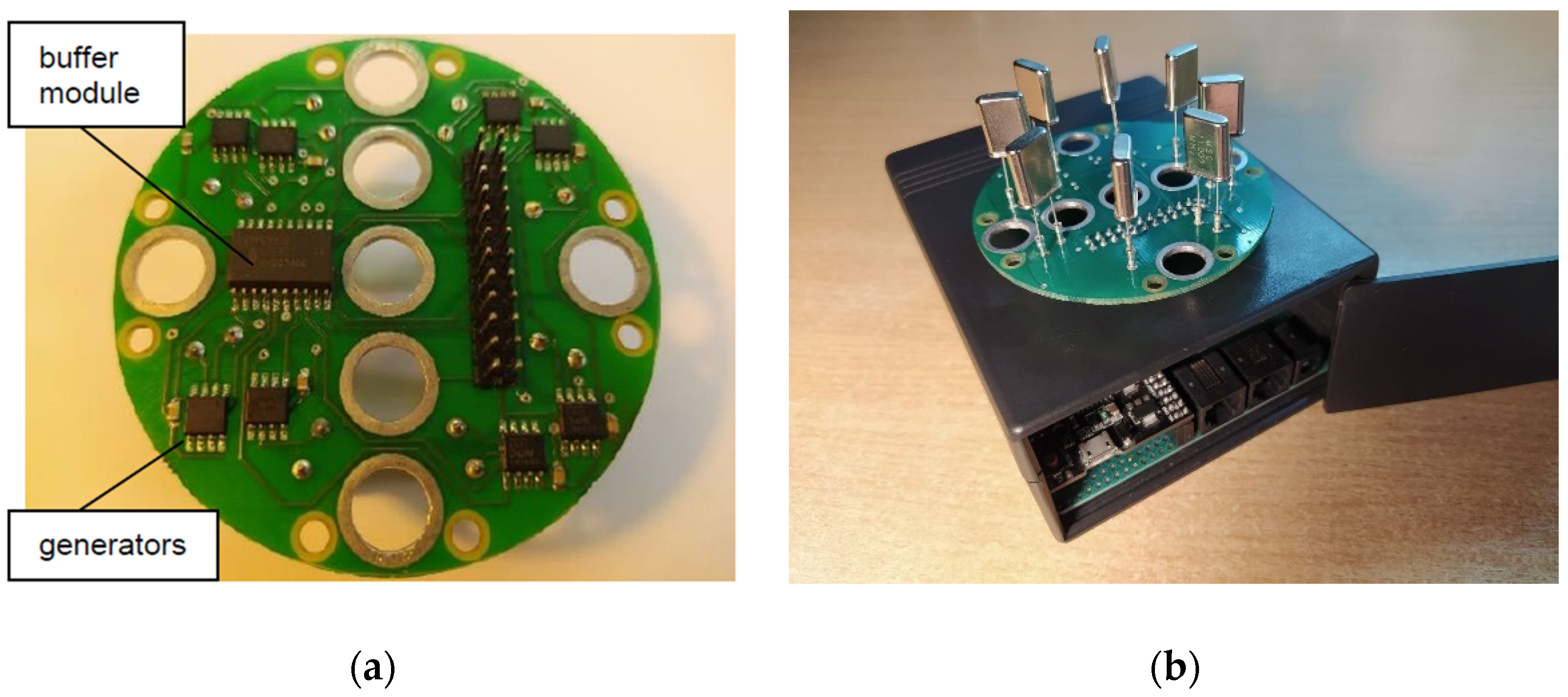
The frequency generation module consists of eight identical elements, one for each channel (
Figure 3). It consists of an oscillator that performs the main function of this block, a quartz resonator, which is a sensor element and simultaneously sets the resonant frequency of the oscillator, and circuits that match the oscillator and resonator (and buffer module on the basis of 74HC541). Each channel is built on a separate quartz square-wave oscillator, implemented on a specialized microcircuit from Nippon Precision Circuits. The microcircuit is designed to connect quartz resonators with a fundamental harmonic frequency from 3 to 40 MHz, providing stable generation of rectangular pulses of a given amplitude. To eliminate the mutual influence of generators, to eliminate the effect of “frequency capture” of adjacent channels, an inductive-capacitive filter is implemented for each generator in the power circuit. The block of generators is made on double-sided printed circuit boards manufactured according to 200micron technology (IV class of accuracy in the manufacture of printed circuit boards).
To match the frequency of the generators and adjust the registration of the microprocessor module, frequency dividers by 2, 4, 8, 16 are used, implemented on four D-flip-flops of the 74HC74 type and a channel selector.
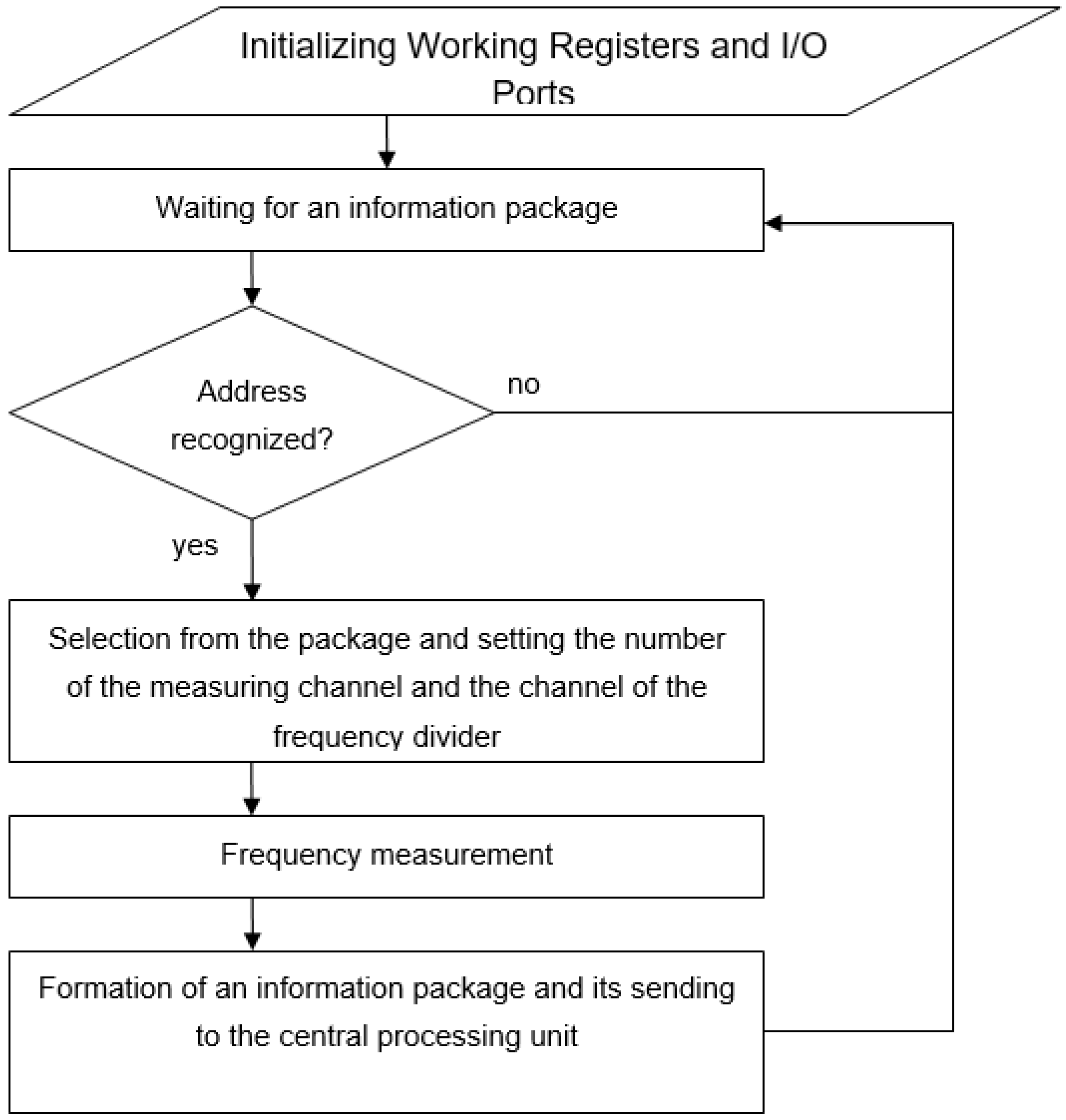
An essential element of the operation of the device is the firmware stored in the memory of the microcontroller. This program contains the operation logic of the entire device and is logically linked to the software running at the central station and main computer. When the device is connected to a power source, the controller circuits are initialized and this program is launched. First of all, the program initializes the working registers and programsthe input-output ports. After that, the device is completely ready for operation and enters the mode of waiting for commands from the central station. Each measuring module has its own unique address within the local network. The versatility of this approach lies in the independence of the network from the method of data transmission (wired/wireless) and the configuration of the network itself (connections of the “star” type or “serial” connection of modules). The central station sends a data packet containing the address of the requested module. Each measurement module in the network receives this packet. The module, which has recognized its address, starts processing the incoming command, extracting from it the number of the measuring channel and the number of the frequency divider channel. The microcontroller makes the corresponding settings of the channel switch circuit registers, and performs the frequency measurement. Then an information packet is formed and sent back to the local network to the central processing unit. The block diagram of the microprogram operation protocol is shown in
Figure 4.
4. Concluding Remarks
In this study, an important scientific and practical problem of complex gas mixture monitoring is solved by forming a unique “chemical image of the CGM” using an intelligent gas analyzer based on a cross-reactive array of chemical sensors using piezoelectric elements of a quartz crystal microbalance (QCM) as physical transducers. The originality of this work lies in the formation of a network of such intelligent analyzers connected by means of telecommunication protocols for the operational control of the perimeter of a protected and/or dangerous zone by monitoring the gaseous environment. Registration and communication systems are built on commercially available modules, which ensures cost-effectiveness and ease of repair if necessary. A variety of devices, such as sensors for temperature, humidity, light, atmospheric pressure, CO or CO2 concentrations, soil moisture, soil saturation, mineral components, current and voltage of the solar battery, etc. can be added to the system, if necessary. Individual modules can be connected in a network of various configurations using both wired and wireless protocols. Typical examples of the use of such systems are the control of technological processes, a security alarm regarding high-risk objects and the generation of information about the danger in order to prevent personnel from entering an area with a potentially hazardous atmosphere of the working area.


