Proceeding Paper

Safety Measures for Hydrogen Generation Based on Sensor Signal Algorithms †

by
Francisco Javier Folgado
*,
Isaías González
and
Antonio José Calderón
Department of Electrical Engineering, Electronics and Automation, Universidad de Extremadura, Avenida de Elvas, s/n, 06006 Badajoz, Spain
*
Author to whom correspondence should be addressed.
Presented at the 9th International Electronic Conference on Sensors and Applications, 1–15 November 2022; Available online: https://ecsa-9.sciforum.net/.
Eng. Proc. 2022, 27(1), 24; https://doi.org/10.3390/ecsa-9-13284
Published: 1 November 2022

Abstract

:
In the last decade, the use of electrolyzers in various sectors has facilitated the generation of hydrogen for multiple applications, such as an alternative fuel source for vehicles, generation of green hydrogen through renewable energies, or energy storage through metal hydride tanks, among others. Regardless of their application, electrolyzers are characterised by complex operation and dependence on various operating parameters, which means that their implementation in a real system is not immediate. This paper presents sensor-based algorithms aimed at ensuring safe and stable operation of a Proton Exchange Membrane Electrolyzer (PEMEL) framed within a smart microgrid powered by renewable energy. Algorithms developed to consider factors such as operating temperature and pressure, availability of feed water or the presence of water in the phase separator are presented. The goal of these algorithms is to maintain the operation of the PEMEL within nominal ranges in order to avoid degradation and/or malfunction of the materials and equipment involved in the system. The algorithms are programmed in a programmable logic controller that is responsible for managing the complete operating cycle of the PEMEL. The sensors and actuators are described, together with their relevance in the operation of the PEMEL. Finally, experimental results of their implementation and real-time operation are provided.

1. Introduction

Technological advances in hydrogen generation devices such as the Proton Exchange Membrane Electrolyzer (PEMEL), have led to a new energy revolution. This revolution is aimed at harnessing this new energy source and integrating it with existing renewable energy sources [1]. However, the PEMEL is a complex device and current studies and research is focused on issues such as the design and simulation of models to understand its behaviour [2,3], optimisation of its operation [4] or experimentation on its useful life and degradation [5]. However, despite the importance of these topics, research work on the implementation and control of PEMELs is relevant, as it allows these devices to be integrated into functional installations in an autonomous and safe way.
This article presents a hydrogen generation system framed in a Smart Microgrid and composed of a PEMEL and a set of sensors and actuators. These devices are governed by a Programmable Logic Controller (PLC), in order to ensure a correct and safe operation for all the components of the system. To this end, algorithms are developed and executed in the PLC that limit and control the operation of the PEMEL to avoid possible equipment malfunctions and long-term degradation of its internal components. These algorithms are designed using key parameters such as the working temperature and pressure or input current.
The structure of the rest of the document is as follows: Section 2 describes the PEMEL and the set of sensors and actuators used in the hydrogen generation system. At the same time, the control parameters selected for the management of the system are detailed. Section 3 deals with the implementation of the various control algorithms developed to achieve an autonomous and safe management of the system. Finally, the main conclusions of the work are detailed.

2. Materials and Methods

This section describes the hydrogen generation system integrated in the Smart Microgrid, with emphasis on the operation of the PEMEL and the different sensors and actuators necessary for its correct operation.

2.1. PEM Electrolyzer

The PEMEL is a hydrogen generation device based on electrolysis. Through this electrochemical process, the electrolyzer splits an input compound into its fundamental components, producing hydrogen from the separation of compounds such as carbides or water. For the system described, the PEMEL is fed with distilled water and powered by a renewable energy source, performing the reaction described in Equation (1) and resulting in what is known as green hydrogen.
H 2 O   ( l ) + E n e r g y H 2 ( g ) + 1 2 O 2 ( g )
On a structural level, the electrolyzer is made up of fundamental units called cells, which carry out the electrolysis process. These cells can be combined in series to form a stack. Figure 1 depicts a PEMEL as a stack of cells grouped together, illustrating its structure and operation.

2.2. Sensors and Actuators

In order to achieve safe operation of the PEMEL, it is necessary to measure and act on the key parameters that affect its operation. For this purpose, a series of sensors and actuators governed by a PLC have been installed next to the electrolyzer. The following factors have been considered: working temperature and pressure, input current, water supply, hydrogen production and humidity. Table 1 lists the control parameters together with the different sensors and actuators installed.
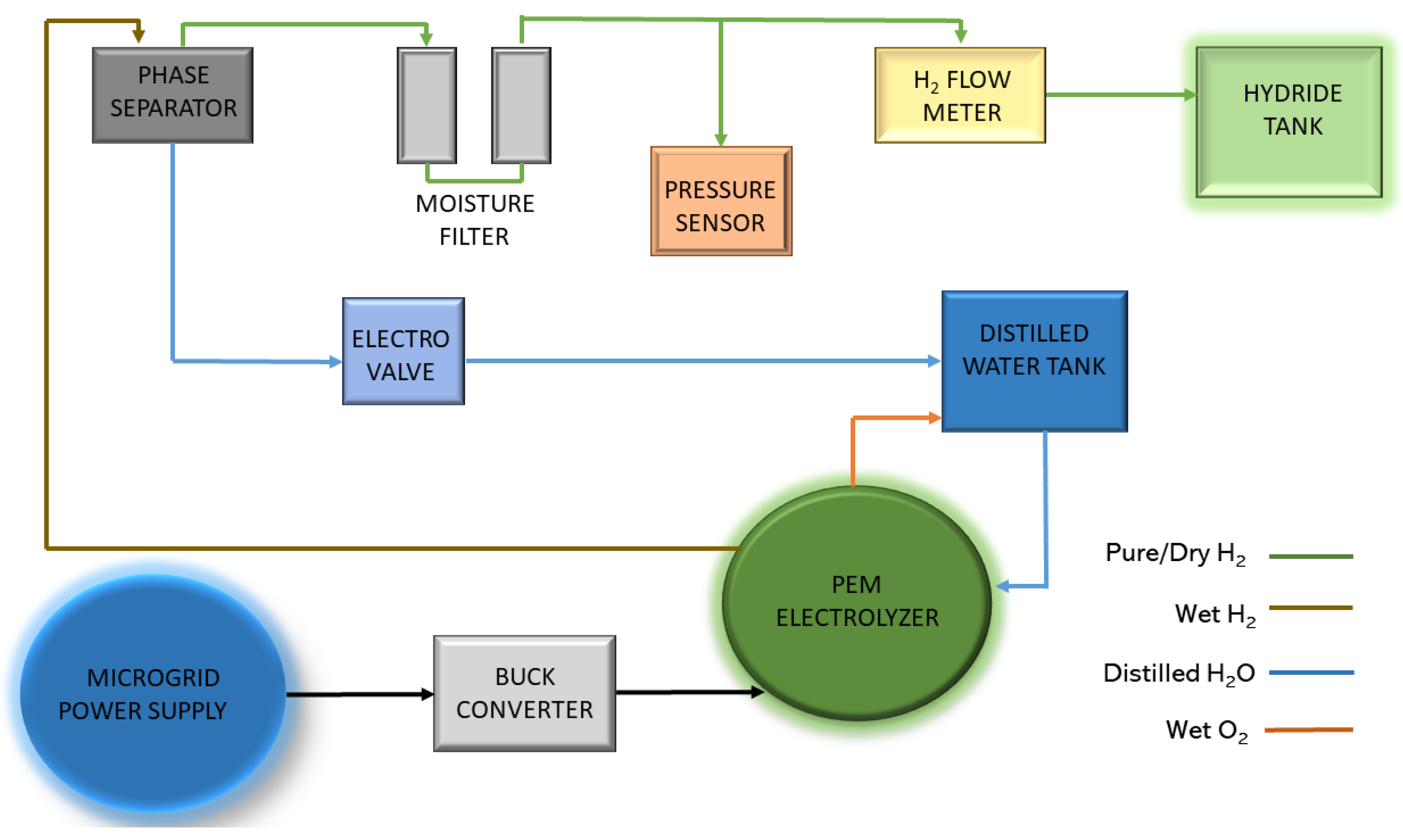
These devices are part of the generation system itself and are arranged and interconnected to produce high purity green hydrogen. The process carried out for the production of hydrogen is described below.
First, an operating point is set for the PEMEL, which starts producing hydrogen by feeding distilled water stored in a tank and drawing power from the Smart Microgrid. After the electrolysis process, the generated oxygen is recirculated to the water feed tank. On the other hand, due to the performance of the electrolyzer, the hydrogen produced contains a percentage of water and is therefore taken to a phase separator. Once in the phase separator, the water content is removed from the hydrogen by gravity and deposited back into the feed tank. The dry hydrogen is then passed through silica filters to ensure a low moisture content. Finally, the gas is stored in a metal hydride tank. Figure 2 shows the hydrogen generation system described, distinguishing the various flows and components involved.

2.3. Control Parameters

With regard to the system control parameters, these have been selected after considering their impact on the performance/operation of the electrolyzer, as well as possible adverse and degrading effects on the PEMEL and the rest of the associated devices.
Starting with the working temperature, this is a fundamental parameter in the operation of the PEMEL, being related to the voltage present in its cells and, therefore, in the overall performance of the electrolyzer. In [6,7], models are developed where it is demonstrated that the efficiency of the PEMEL grows with increases in temperature. However, in practice, this temperature increase must be controlled and limited, since continuous operation at high temperatures can degrade electrolyzer internal components. In addition, operation in this elevated temperature range results in the generation of superheated wet hydrogen and oxygen. This effect causes a constant increase in the temperature of the water stored in the feed tank, as well as the stored dry hydrogen, which can lead to deterioration of the metal hydride tank.
As well as temperature, working pressure plays an important role in the operation and efficiency of the PEMEL, but from a safety point of view, this parameter becomes more critical. By keeping the system pressure below its nominal maximum, possible leaks and equipment damage due to material fatigue and fracture are prevented.
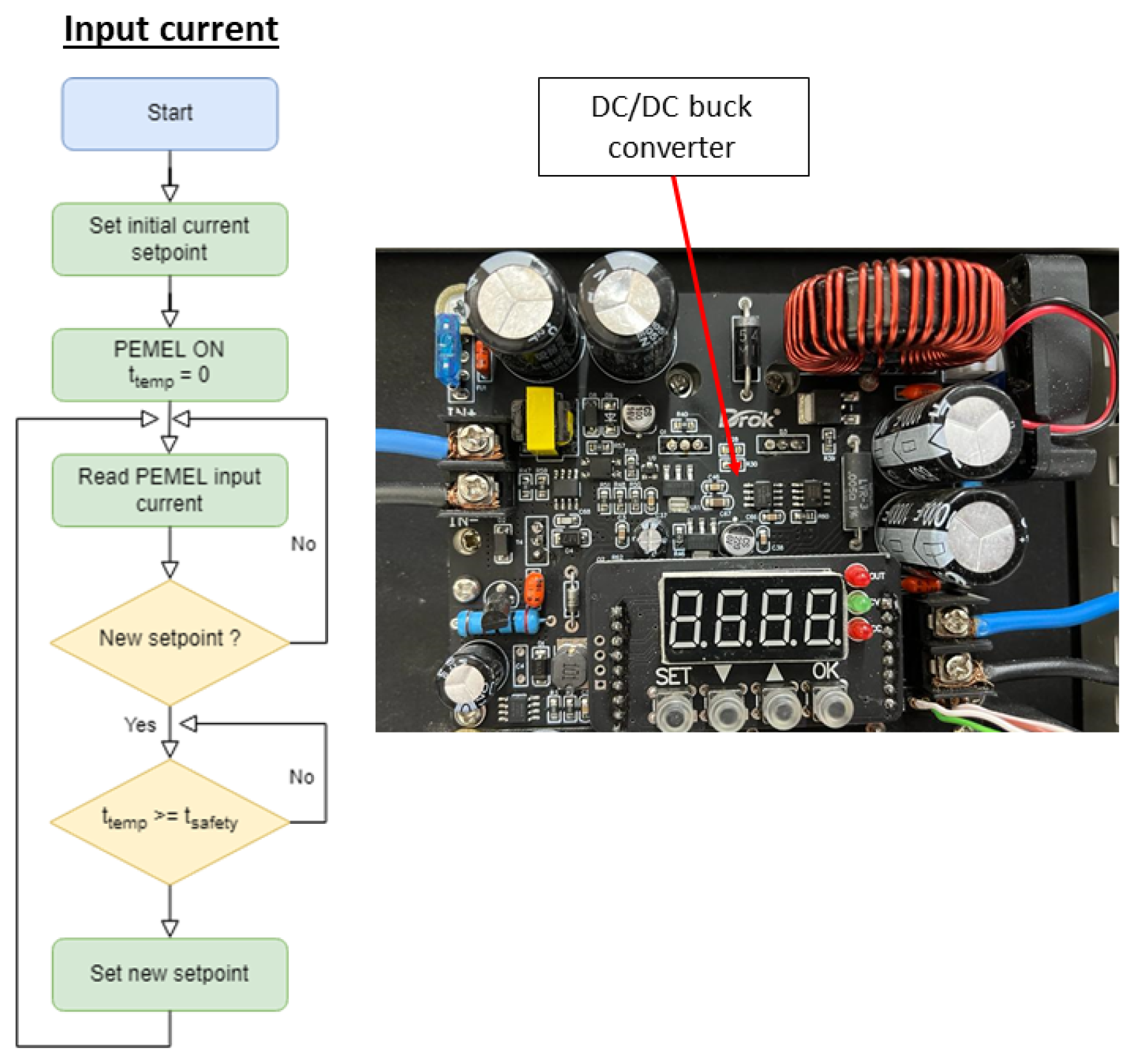
Among the variety of electrolyzer technologies available, PEM types stand out in renewable energy applications due to their rapid adaptability to variations in the current supplied. However, works such as [8] describe the adverse effects of prolonged operation under constant fluctuations in the input current. Therefore, this current is controlled in the system by a DC/DC converter that sets a constant consumption for a certain period of time.
With regard to moisture, the presence of water in the hydrogen generated can lead to the deterioration of sensors that are not adapted to such humidity levels. Likewise, the storage capacity and lifetime of metal hydride tanks can be compromised by the presence of water.
Finally, the availability of feed water to the PEMEL is controlled to ensure an adequate and uninterrupted flow of input water during operation. Operating the PEMEL without water can lead to internal degradation of its components, destroying the membrane and reducing its efficiency.

3. Implementation and Results

This section describes the implementation of the control algorithms for the generation system, and the results obtained in the operation of the PEMEL.

Control Algorithms

Regarding the temperature control of the PEMEL, the value is acquired by means of the PT-100 sensor. This value is then compared with two temperatures: a maximum temperature (Tmax) from which the PEMEL stops production, and a minimum temperature (Tmin) set to start the fan. In relation to the working pressure, a maximum operating value (Pmax) is set which limits the production and storage of hydrogen. This limit is set by reference to the specifications provided by the manufacturers of the PEMEL and the hydride tank. Figure 3 shows the temperature and pressure control by means of flow diagrams, as well as the physical devices involved.
Electro-optical level sensors are used for the feed water and the presence of moisture. For feed water, a high (LHigh) and a low (LLow) sensor are used to monitor the current volume in the tank. If the level is above LHigh or LLow, the PEMEL operates normally. As soon as the level drops below LLow, the electrolyzer stops to avoid idle operation. Regarding the presence of moisture, a level sensor is placed in the phase separator, which controls the operation of an electro-valve that allows the water contained in the wet hydrogen to be purged back to the feed tank. This purging process is performed for a specific time according to a timer, which minimises hydrogen leakage in the system. Figure 4 shows the flow chart control algorithms for feed water availability and the presence of moisture. The physical components of the system involved are also shown.
The current consumed by the PEMEL is supplied and controlled by a DC/DC converter, which ensures a continuous consumption without fluctuations during a programmed time. Figure 5 shows the flow diagram associated with this control, as well as the appearance of the converter.
Finally, all the results obtained from the operation of the system after implementing the management described above are shown. Figure 6 depicts the input current and H2 flow curve for a time interval of two hours in a continuous, uninterrupted operation.

4. Conclusions

This article has presented a hydrogen generation system managed by means of control algorithms based on sensor signals. The PEMEL has been described as the central core of the system, with emphasis on its operating principle and structure. The set of sensors and actuators used and their relationship with the selected control parameters have been detailed. The selection of these parameters has been made considering performance and safety aspects of the system. Finally, the different control algorithms implemented in the PLC for the management of the system have been described, indicating the components involved in each of them. Further research guidelines include studying long-term operation of the PEMEL under the control of the reported algorithms.

Author Contributions

Conceptualization, F.J.F. and I.G.; Methodology, I.G.; Software, F.J.F. and I.G.; Validation, A.J.C.; Investigation, F.J.F., I.G. and A.J.C.; Data curation, F.J.F.; Writing—original draft preparation, F.J.F. and I.G.; Writing—review and editing, I.G. and A.J.C.; Supervision, I.G. and A.J.C.; Project administration, A.J.C.; Funding acquisition; A.J.C. All authors have read and agreed to the published version of the manuscript.

Funding

This research received no external funding.

Institutional Review Board Statement

Not applicable.

Informed Consent Statement

Not applicable.

Data Availability Statement

Data sharing not applicable.

Conflicts of Interest

The authors declare no conflict of interest.

References

  1. González, I.; Calderón, A.J.; Andújar, J.M. Novel remote monitoring platform for RES-hydrogen based smart microgrid. Energy Convers. Manag. 2017, 148, 489–505. [Google Scholar] [CrossRef]
  2. Awasthi, A.; Scott, K.; Basu, S. Dynamic modeling and simulation of a proton exchange membrane electrolyzer for hydrogen production. Int. J. Hydrog. Energy 2011, 36, 14779–14786. [Google Scholar] [CrossRef]
  3. Folgado, F.J.; González, I.; Calderón, A.J. Simulation platform for the assessment of PEM electrolyzer models oriented to implement digital Replicas. Energy Convers. Manag. 2022, 267, 115917. [Google Scholar] [CrossRef]
  4. Scheepers, F.; Stähler, M.; Stähler, A.; Rauls, E.; Müller, M.; Carmo, M.; Lehnert, W. Improving the efficiency of PEM electrolyzers through membrane-specific pressure optimization. Energies 2020, 13, 612. [Google Scholar] [CrossRef] [Green Version]
  5. Feng, Q.; Yuan, X.Z.; Liu, G.; Wei, B.; Zhang, Z.; Li, H.; Wang, H. A review of proton exchange membrane water electrolysis on degradation mechanisms and mitigation strategies. J. Power Sources 2017, 366, 33–55. [Google Scholar] [CrossRef]
  6. Atlam, O.; Kolhe, M. Equivalent electrical model for a proton exchange membrane (PEM) electrolyser. Energy Convers. Manag. 2011, 52, 2952–2957. [Google Scholar] [CrossRef]
  7. Guilbert, D.; Vitale, G. Dynamic emulation of a PEM electrolyzer by time constant based exponential model. Energies 2019, 12, 750. [Google Scholar] [CrossRef] [Green Version]
  8. Weiß, A.; Siebel, A.; Bernt, M.; Shen, T.-H.; Tileli, V.; Gasteiger, H.A. Impact of Intermittent Operation on Lifetime and Performance of a PEM Water Electrolyzer. J. Electrochem. Soc. 2019, 166, F487–F497. [Google Scholar] [CrossRef]
Figure 1. Structure and operation of a PEMEL.
Engproc 27 00024 g001
Figure 2. PEMEL hydrogen generation system.
Engproc 27 00024 g002
Figure 3. Control algorithms for temperature and pressure and equipment involved.
Engproc 27 00024 g003
Figure 4. Control algorithms for feed water and presence of moisture. Equipment involved.
Engproc 27 00024 g004
Figure 5. Control algorithms for the PEMEL input current and the related DC/DC converter.
Engproc 27 00024 g005
Figure 6. Input current and H2 flow curve.
Engproc 27 00024 g006
Table 1. Control parameters, sensors, and actuators.
Control ParametersTypologyModel/Type
Working temperatureSensorPT-100
ActuatorDC fan
Working pressureSensorWika A-10
Input currentSensorHall-effect sensor
ActuatorDC/DC buck converter
Water supplySensorElectro-optical level sensor
Hydrogen productionSensorMass flow meter
Water presence/moistureSensorElectro-optical level sensor
ActuatorElectrovalve
Publisher’s Note: MDPI stays neutral with regard to jurisdictional claims in published maps and institutional affiliations.