1. Introduction
Zinc is a chemical element with the element symbol Zn and is the 24th most abundant element on earth with a content of 0.0076% [
1]. The global demand for zinc is increasing. It amounted to 13.4 Mt in 2018 [
2]. The applications of zinc and its alloys are very numerous. More than 50% of the zinc produced worldwide is used for corrosion protection of steel. The use for zinc dye casting or as an alloying additive in brass is the second highest application of zinc with 17% each. In addition, 6% of the world’s zinc production is used for semi-finished products for roofs, facades, and roof drainage. Another 6% are used for zinc compounds such as zinc oxide or zinc sulphate [
3].
In forging, zinc is mainly used as an alloying component in brass. Today, brass is found especially in applications such as in the sanitary, the fittings, and the electrical industry, where components such as fittings, valves, door fittings, locks, and plugs are manufactured. Many brasses, especially free-cutting brass CuZn39Pb3, are to be regarded critically due to their lead content after the European health authorities established the toxicity of lead even in very small quantities [
4]. In connection with the resulting conversions, lead-free wrought zinc alloys in bar form were developed as a substitute for brass. Zinc extrusion products, ZEP for short, are novel wrought zinc-based alloys that differ from other alloys in their good formability and meet the highest demands on material quality and achievable manufacturing tolerances [
5].
The alloying elements of this wrought zinc alloy were put together with the aim of creating an environmentally friendly and lead-free alternative for brass alloys, especially for brass CuZn39Pb3, without having any mechanical and physical disadvantages [
6]. In addition to being environmentally friendly during production and further processing, ZEP1510 (consisting of up to 15% secondary aluminum, 1% copper, and 0.1% magnesium) has other advantages over CuZn39Pb3 (see
Figure 1). The 15% higher electrical conductivity offers great potential for several products in the innovative field of electromobility [
7], which are currently manufactured with copper and copper alloys. In addition, the 20% higher yield strength combined with low weight enables the use of ZEP1510 in light- weight construction applications. Energetically and economically, the use of wrought zinc alloys makes sense due to the realisation of enormous cost advantages and CO2 savings in the process chain [
8]. In this study, the aim is to investigate the fundamental forming behavior of ZEP1510 and compare it with other materials used usually as substitutes. Furthermore, another objective is to produce and investigate selected industry-relevant products manufacturable using ZEP1510.
2. Experimental Procedure
2.1. Laboratory Level
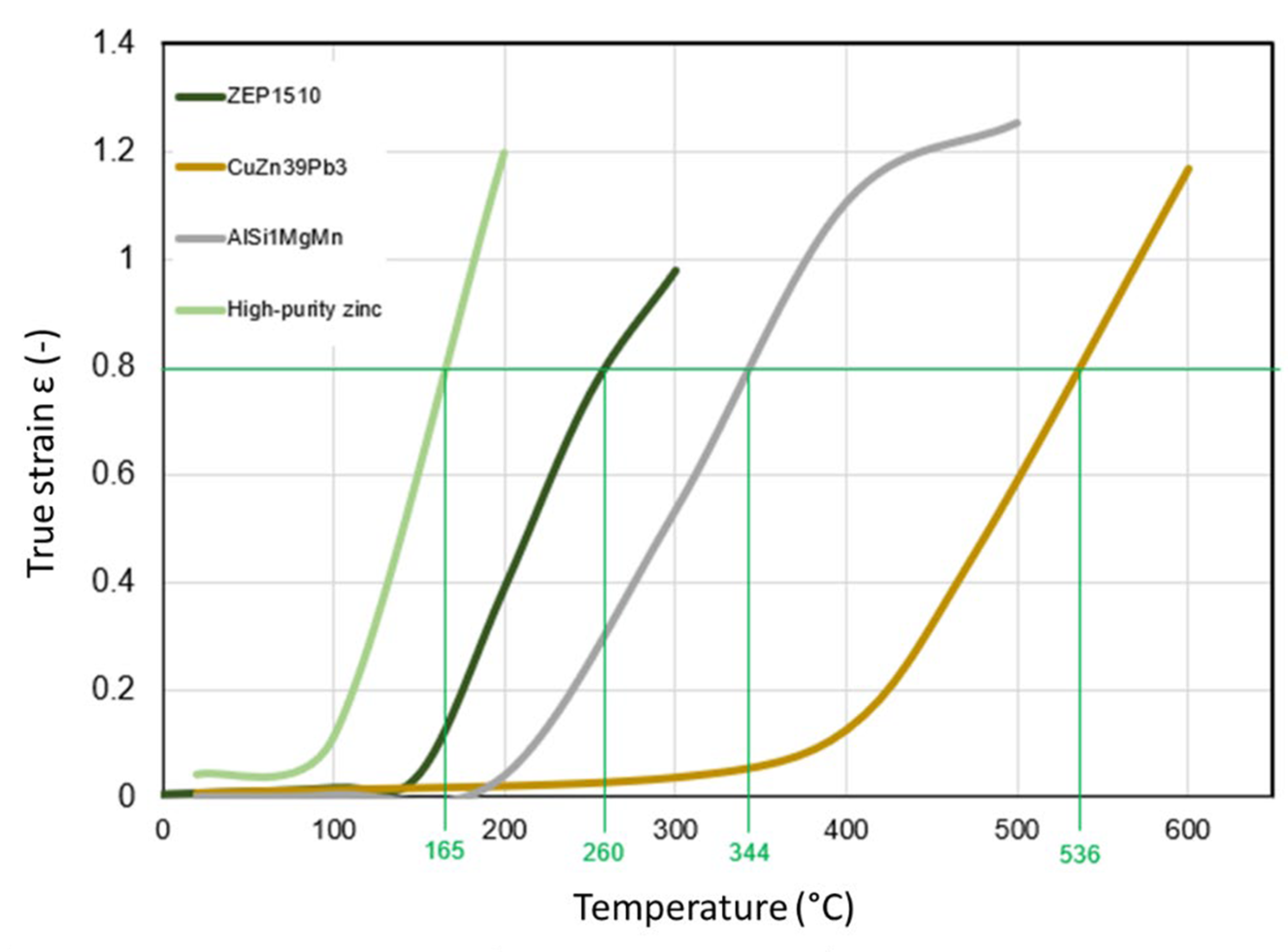
To determine the fundamental forming behaviour and forming capacity of wrought zinc alloys, various experimental investigations were carried out on a hydraulic press. The aim is to determine the material characteristic and process engineering correlations as well as process limits of wrought zinc alloys. The achievable forming limits ε at typical process temperatures of ZEP1510 were determined with the aid of compression tests and com- pared with high purity zinc, CuZn39Pb3, and AlSi1MgMn. The initial diameter of the samples is 34 mm and the initial height is 47 mm. The tests were carried out with a defined pressing force F of 150 kN.
The limit of buckling risk during compression is indicated by the upset ratio [
9], which is the ratio of specimen height
h0 to specimen diameter
d0 in the non-formed state:
The permissible compression ratio for upsetting is given in the literature as
s ≤ 2.6 [
9]. However, as there is no clear definition of a permissible compression ratio for zinc and copper alloys in the literature, tests were carried out with the samples listed in
Table 1.
If the permissible deformation capacity of a material is exceeded, cracks appear on the component [
10]. For a sufficient process design, it is important to know the allowable forming capacity. For this reason, a test was carried out to determine the cracking of ZEP1510 during upsetting and to compare it with CuZn39Pb3 and AlSi1MgMn. Crack detection is carried out with an infrared thermal imaging camera (IR camera). The permanent video recording of the forming process makes it possible to document the complete cooling or heating during the forming process. If cracks occur on the surface of the com- ponent during these forming processes, this is shown in a changing color within the image (see
Figure 2). This is due to temperature differences between the core (or crack surface) and the surface of the component. Another detection feature could be the heating of air inside the gap, which is again visible in color on the IR camera. This method for crack detection was investigated in [
11].
The challenge that arises here follows from the rapid cooling of the surfaces created by the crack. As a result, the video recording must be faster (FPS) than the cooling of the crack site. Furthermore, only the cracks that are in the recording range of the IR camera can be detected. The IR camera
VarioCAM (see
Table 2) from the company
InfraTec GmbH was used for the tests. With the help of the
IRBIS 3 Plus evaluation software, temperatures were recorded and saved during the upsetting process. Minimum, maximum, and average values could be output. It is important to note that the correction factor or emissivity must be adjusted for each material. The emissivity is 0.4–0.5 for ZEP1510, 0.25–0.35 for AlSi1MgMn, and 0.5–0.6 for CuZn39Pb2. This test was also carried out with the materials ZEP1510, CuZn39Pb2, and AlSi1MgMn. The samples have a diameter of 34 mm and a height of 55 mm. The approximate forging temperature was set as the initial temperature for all three materials. This is approx. 250 °C for ZEP1510, approx. 750 °C for CuZn39Pb2, and approx. 500 °C for AlSi1MgMn. In all tests, a dispersion of graphite and water was used as the lubricant. The initial temperature was lowered in 50 °C steps until cracks appeared at the existing degree of deformation. All laboratory-level investigations carried out were proven at least five-fold.
2.2. Application Level
To identify the potential of zinc-formed parts and to verify the results obtained at laboratory level at the application level, fields of application are sought whose requirements are fulfilled by substitution and whose use appears to make production-wise sense taking into account energetically and economically aspects. Brass-formed parts are hereby considered as a benchmark. The market research into possible fields of application was carried out based on the specific material properties of the wrought zinc alloys. The fields of application were identified that appear to be the most suitable from the point of view of resource efficiency. After the screening, two components were selected and produced by forming. In the process design, the results of the tests at the laboratory level were also considered.
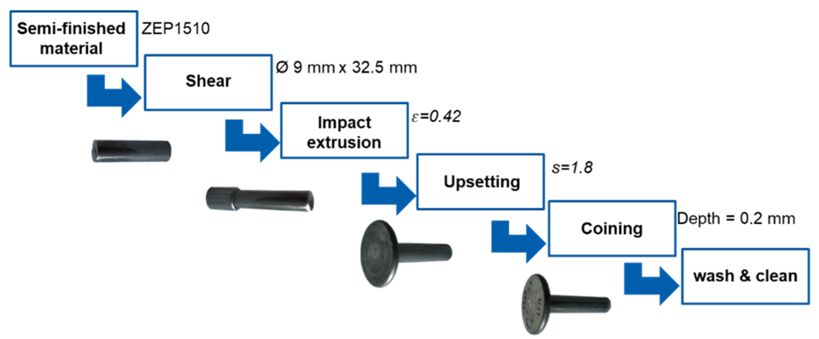
For the verification of possible formed parts that could be produced by impact extrusion, i.e., cold, a demonstration component was developed and prototyped with the industrial partner Möhling GmbH & Co. KG and tested as a prototype. Three forming processes are needed to produce the component. These are:
full forward extrusion with a forming ratio of ε = 0.42;
head upsetting with an upsetting ratio of s = 1.8;
coining with a depth of 2 mm.
Bars with a diameter of 9 mm were used as semi-finished products, which were sheared to a length of 32.5 mm. After passing through the forming stages, the components were cleaned. The lubricant application is usually divided into two steps, namely surface pre-treatment and the application of lubricant. Surface pre-treatment is not necessary for ZEP1510 due to the alloy. For cold forming of ZEP1510, forming oils are recommended. The lubricant used in the tested cold forming processes was the metalworking oil Beruform MF 155 from Carl Bechem GmbH.
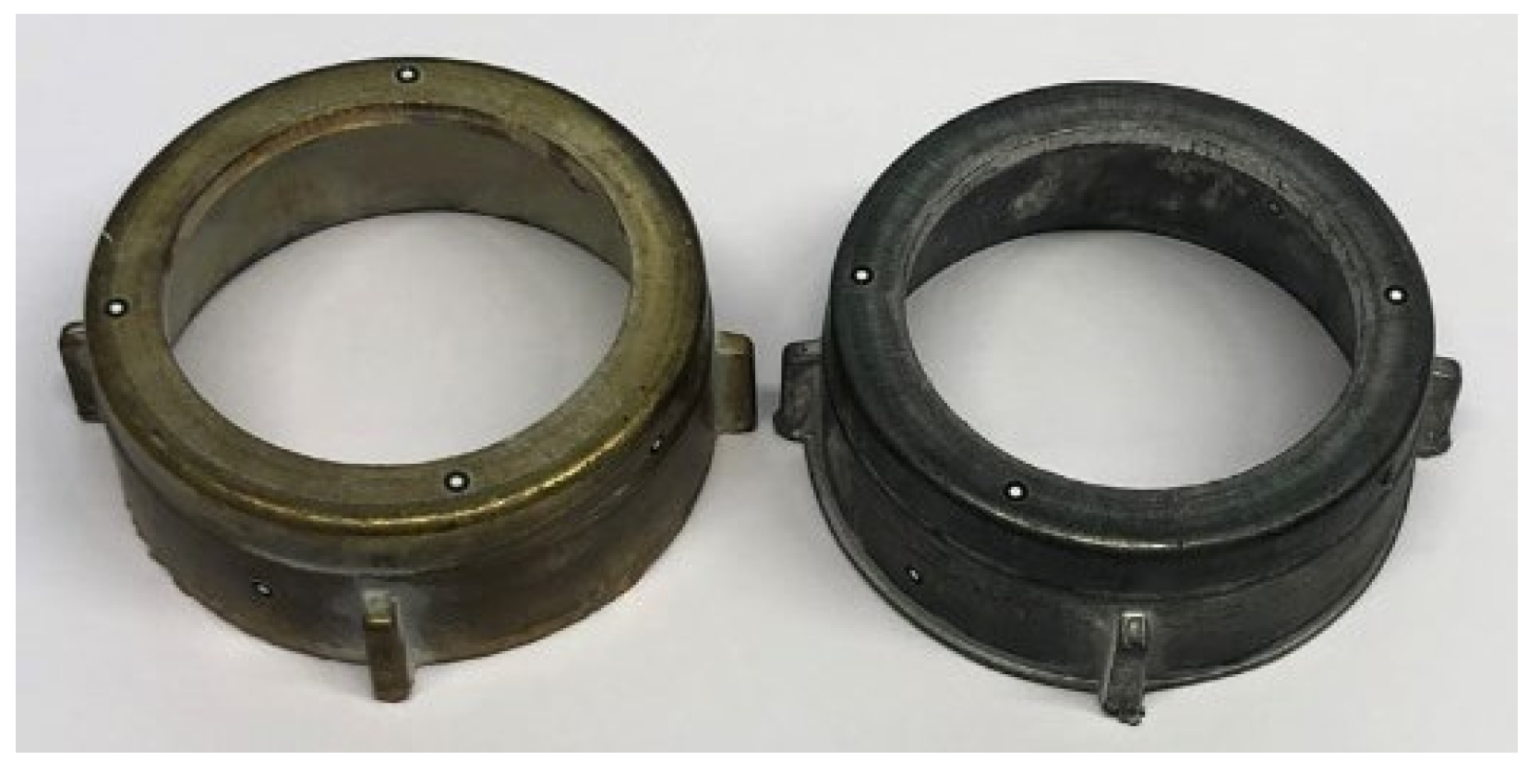
For the verification of possible formed parts that are produced by forging, i.e., by hot forming, two wet-rotor heads, one made of ZEP1510 and one made of CuZn39Pb3, were produced at the cooperation partner Metallpresswerk Hohenlimburg GmbH and compared with each other. The required forging temperature of the component using the material ZEP1510 is approx. 250 °C, while in the case of CuZn39Pb3, it is approx. 750 °C.
3. Results and Discussion
3.1. Laboratory Level
3.1.1. Formability
Figure 3 shows the formability of ZEP1510, high-purity zinc, CuZn38Pb3, and AlSi1MgMn as a result of temperature. With a defined maximum pressing force of 150 kN, a degree of deformation of 0.8 is achieved at approx. 260 °C for ZEP1510. With the free-cutting brass CuZn39Pb3, this degree of deformation can be achieved with the de- fined maximum force at 536 °C. This large reduction in processing temperature offers great energy-saving potential in hot forming. From these experiments, it is clear that targeted temperature control during the hot forming of ZEP1510 is important for the achievable forming degrees.
3.1.2. Upset Ratio
Table 3 shows the results of the tests for determining the upset ratio at elevated temperature. For ZEP1510 and CuZn39Pb3, the permissible upset ratio was observed between 2.9 and 3.4. For AlSi1MgMn, the permissible upset ratio is indicated between 3.5 and 4.3. A high upset ratio helps to produce components in fewer stages. However, if the forming ratio is too high, there is a risk of cracks appearing around the circumference of the com- ponent.
3.1.3. Permissible Deformation Capacity
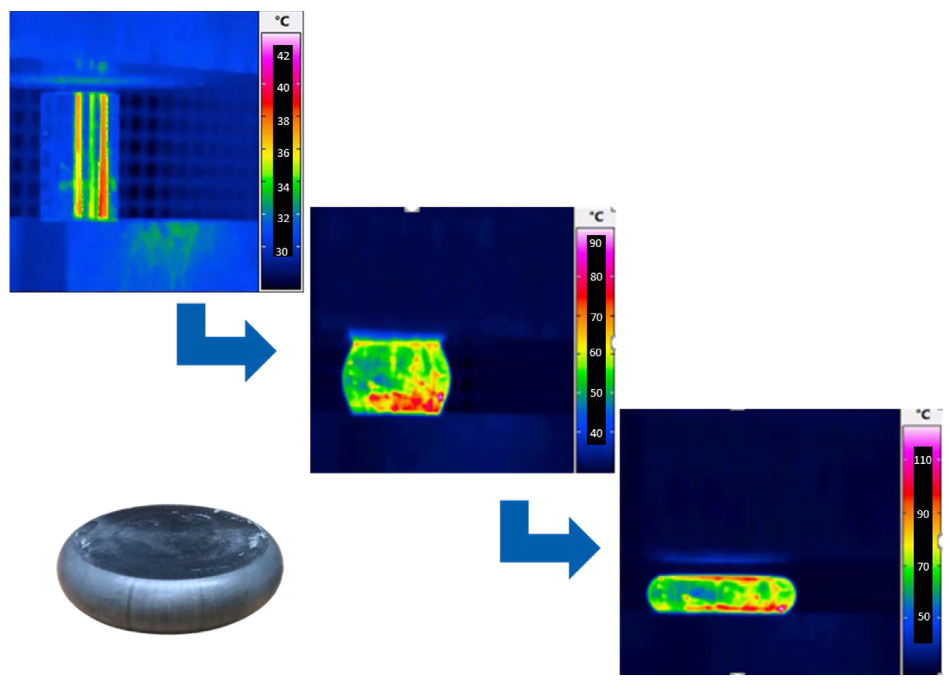
The initial temperatures mentioned in the test description were reduced in 50 °C steps until cracks appeared in the existing forming. In the case of ZEP1510, the initial temperature was reduced step by step from 250 °C to 30 °C. Unexpectedly, no surface cracks appeared despite the lower temperature (see
Figure 4).
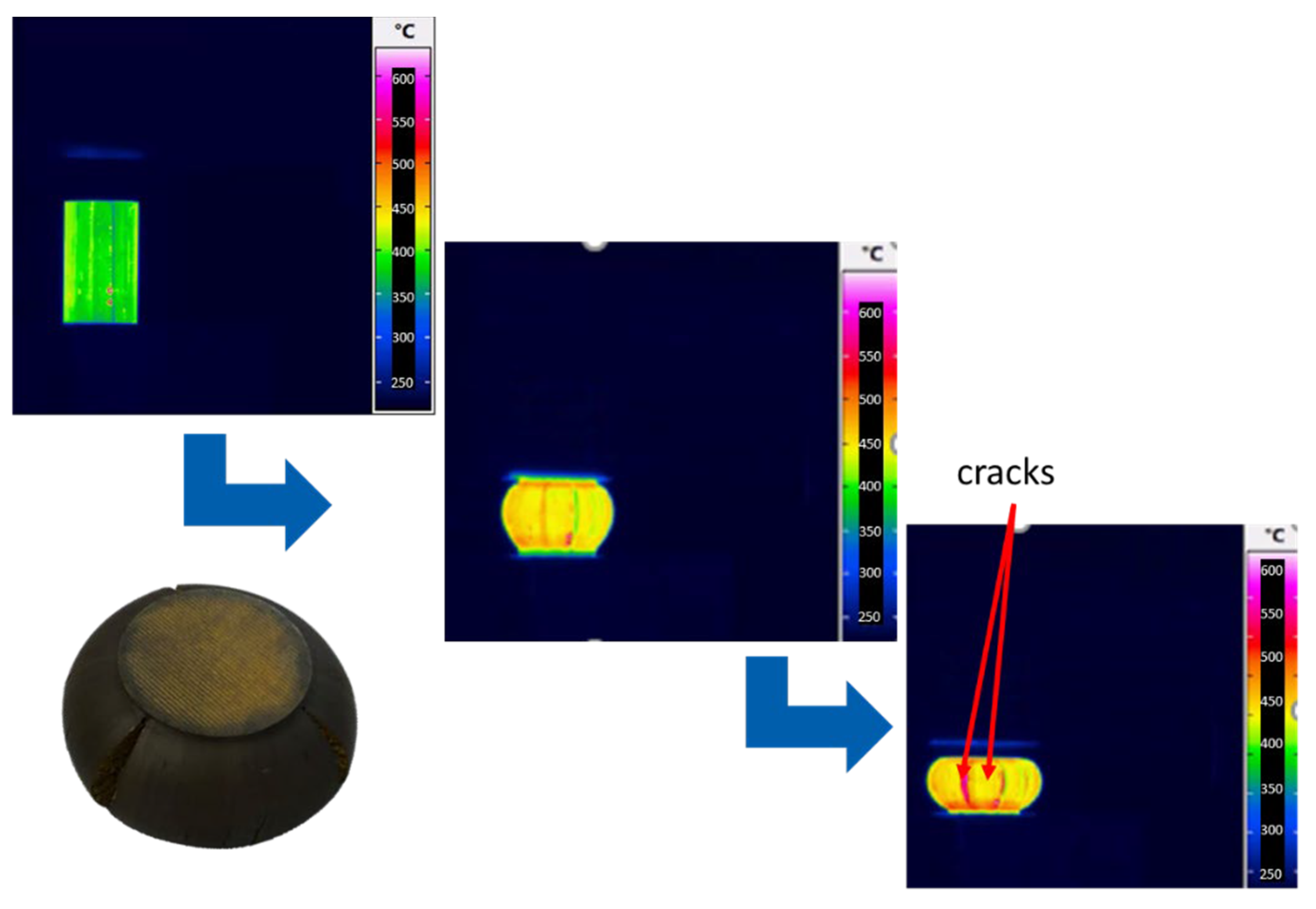
In the case of CuZn39Pb3, the upsetting temperature was reduced step by step from 750 °C onwards. During the upsetting tests with an initial temperature of 450 °C, cracks appeared that can be clearly seen with the IR camera (see
Figure 5).
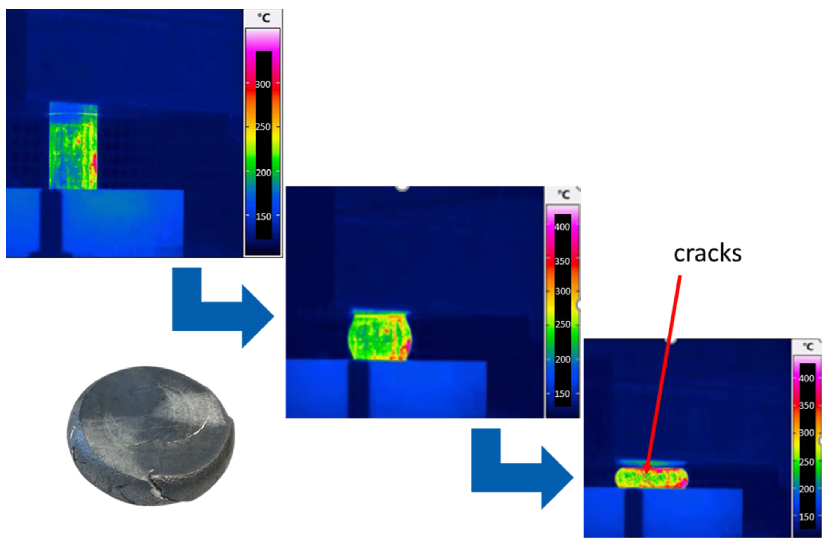
In the case of AlSi1MgMn, the upsetting temperature was lowered step by step from 500 °C onwards. During the upsetting tests with an initial temperature of 200 °C, cracks appeared that can be clearly seen with the IR camera (see
Figure 6).
3.2. Application Level
3.2.1. Cold Forging
Figure 7 shows the manufactured component from ZEP1510. The same forming ma- chines have been used for cold forming ZEP1510 as for forming copper alloys. A three- stage cold extrusion press was used to produce the component from ZEP1510. Through the tested procedures and process limits, it was found that ZEP1510 has good cold forming properties despite its hexagonal lattice structure.
ZEP has good cold forming properties, although a hexagonal lattice structure pre- dominates. However, many products that are manufactured today by cold forging using conventional copper and brass alloys may be substituted. In addition to the forming pro- duction, the requirements of each product must be taken into account in the application, as ZEP can show differences compared to copper alloys due to its hexagonal lattice structure. Products where substitution is conceivable are, for example, boundary points, rivets, and connectors.
3.2.2. Warm Forging
The warm forming of the component with ZEP1510 works very well (see
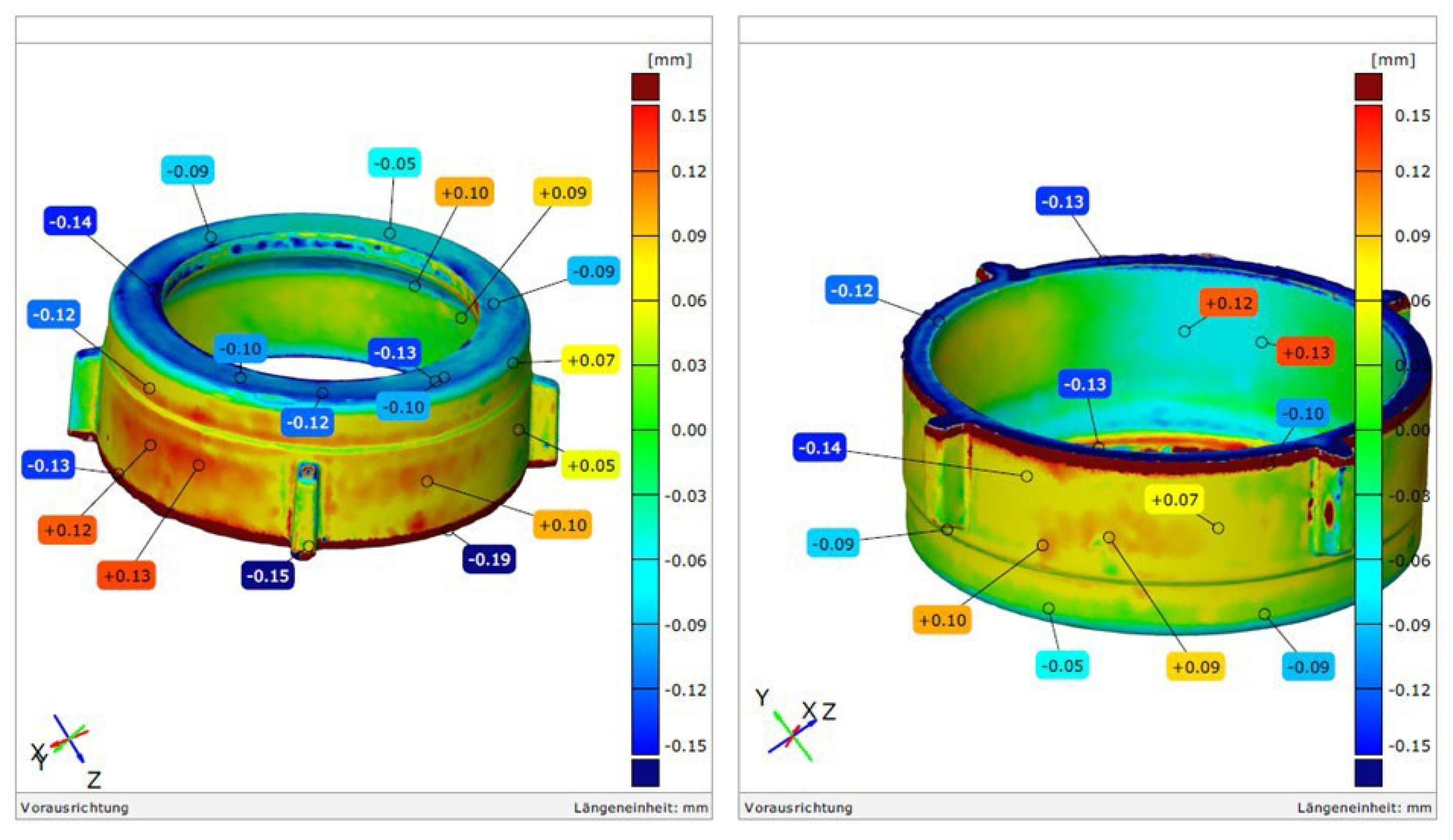
Figure 8). The false colour comparison (see
Figure 9) shows that there are dimensional deviations in the mould filling compared to brass. For this purpose, both scanned models were com- pared to each other in order to check the dimensional deviations. The geometry change comes from the fact that the forming temperatures are 500 °C lower than when forming brass. With smaller (−0.19 to +0.15 mm) adjustments to the tool engraving, the mould filling can be optimised.
4. Conclusions
Having identified the toxicity of lead even in very small quantities, the European health authorities have repeatedly reiterated the need to reduce the concentration of this material as much as possible in various sectors. As a result, the use of free-cutting brass will no longer be possible or will have to be greatly reduced. The use of wrought zinc alloys in massive forming offers a cost-efficient changeover from lead-containing to lead- free materials.
In this paper, the formability of wrought zinc alloys was analysed and verified in an industrial environment. First of all, the application fields were found whose requirements are fulfilled by the technical properties of the zinc forming part and whose use is energetically as well as economically reasonable. Brass-formed parts were primarily considered as a benchmark. These parts were produced with wrought zinc alloys in an industrial environment. For the determination of forming process limits, upsetting tests for the determination of formability, the determination of the upsetting ratio, and the determination of shear cracks were carried out with wrought zinc alloys and compared with other materials. The processing temperature of ZEP1510 is 400–500 °C lower than brass. There- fore, less energy is required for processing. The investigations to determine the upset ratio have shown that the permissible upset ratio during hot forging is the same as brass and lower than aluminium. The results for the determination of shear cracks show that despite the reduced temperature, no cracks occurred during the upsetting of ZEP1510. Thus, high share rates can be achieved in one step.
In this research project, the first progress was made in the forming of wrought zinc alloys. Particularly in cold forging, new knowledge has been gained that can be introduced into industrial practice.
Author Contributions
Conceptualization, A.K. and M.M.; methodology, A.K. and M.M.; formal analysis, A.K.; investigation, A.K.; writing—review and editing, A.K and M.M.; visualization, A.K.; project administration, A.K. and M.M.; funding acquisition, M.M. All authors have read and agreed to the published version of the manuscript.
Funding
This research was funded by The German Federal Environmental Foundation (DBU), grant number 35420/01.
Institutional Review Board Statement
Not applicable.
Informed Consent Statement
Not applicable.
Data Availability Statement
No new data were created or analyzed in this study. Data sharing is not applicable to this article.
Acknowledgments
The authors would like to express their gratitude to the German Federal Envi- ronmental Foundation (DBU) for their financial support. In addition, the authors would like to thank Gesamtverband der Deutschen Buntmetallindustrie e.V., Möhling GmbH & Co. KG, Müller Engineering GmbH & Co. KG, Grillo-Werke AG, Metallpresswerk Hohenlimburg GmbH, and Carl Bechem GmbH.
Conflicts of Interest
The authors declare no conflict of interest.
References
- Institut für Seltene Erden und Metalle AG. Zinc Price, Occurrence, Extraction and Use. Available online: https://en.institut-sel-tene-erden.de/seltene-erden-und-metalle/basismetalle/zink/ (accessed on 2 August 2022).
- Global Zinc Market to Grow at 3.8% in 2022. Available online: https://www.mining-technology.com/comment/zinc-outlook-2019/ (accessed on 2 August 2022).
- Grund, S.; van Genderen, E.; van Leewen, M. Nachhaltigkeit—Verantwortung—Zink. In Proceedings of the GfKORR Annual Conference 2019, Frankfurt am Main, Germany, 12–13 November 2019. [Google Scholar]
- EUR-Lex. Directive 2011/65/EU of the European Parliament and of the Council of 8 June 2011 on the Restriction of the Use of Certain Hazardous Substances in Electrical and Electronic Equipment (Recast) Text with EEA Relevance; EUR-Lex: Luxembourg, 2011. [Google Scholar]
- Deutsches Kupferinstitut Auskunfts- und Beratungsstelle für die Verwendung von Kupfer- und Kupferlegierungen: Messing—Ein moderner Werkstoff mit langer Tradition, Solarpraxis Supernova AG. 2001. Available online: https://kupferinstitut.de/wp-content/uploads/2019/09/i_messing02.pdf (accessed on 2 August 2022).
- The New Generation of Efficient and Sustainable Zinc Alloys. Available online: https://grillo.de/wp-content/uploads/2014/08/grillo_flyer_zep_englisch_v2_141019.pdf (accessed on 2 August 2022).
- Marré, M.; Grupp, P. Innovative Fertigungskonzepte für die Elektromobilität. In Proceedings of the Conference 33. Jahrestreffen der Kaltmassivum-former 2018, Düsseldorf, Germany, 7–8 February 2018. [Google Scholar]
- van Wesel, M. Grillo-ZEP®—Technical Presentation; Grillo-Werke AG: Duisburg, Germany, 2022. [Google Scholar]
- Dietrich, J. Stauchverhältnis. In Praxis der Umformtechnik; Springer Vieweg: Wiesbaden, Germany, 2018; Volume 12, pp. 25–27. [Google Scholar]
- Tschätsch, H. Fehler beim Stauchen. In Praxis der Umformtechnik; Springer Fachmedien Wiesbaden GmbH: Dresden, Germany, 2005; Volume 8, pp. 27–43. [Google Scholar]
- Yang, J.; Wang, W.; Lin, G.; Li, Q.; Sun, Y.; Sun, Y. Infrared Thermal Imaging-Based Crack Detection Using Deep Learning. IEEE Access 2019, 7, 182060–182077. [Google Scholar] [CrossRef]
| Publisher’s Note: MDPI stays neutral with regard to jurisdictional claims in published maps and institutional affiliations. |
© 2022 by the authors. Licensee MDPI, Basel, Switzerland. This article is an open access article distributed under the terms and conditions of the Creative Commons Attribution (CC BY) license (https://creativecommons.org/licenses/by/4.0/).


