Proceeding Paper

Implementation of an Electro-Hydraulic Drive Unit with Two Control Variables in a Drawing Cushion Application †

1
Fraunhofer Institute for Machine Tools and Forming Technology (IWU), 09126 Chemnitz, Germany
2
Parker Hannifin Manufacturing Germany GmbH & Co. KG, 09116 Chemnitz, Germany
3
Machine Tools Development and Adaptive Controls, Institute of Mechatronic Engineering, Technische Universität Dresden, Helmholtzstr 7a, 01069 Dresden, Germany
*
Author to whom correspondence should be addressed.
Presented at the 28th Saxon Conference on Forming Technology SFU and the 7th International Conference on Accuracy in Forming Technology ICAFT, Chemnitz, Germany, 2–3 November 2022.
Eng. Proc. 2022, 26(1), 18; https://doi.org/10.3390/engproc2022026018
Published: 15 November 2022

Abstract

:
Forming machines and their subsystems, e.g., the drawing cushion in sheet metal-forming machines, pose high power as well as precision requirements in both the positioning and the force, which are directly linked to the quality of the produced part. In addition to ensuring quality, energy efficiency becomes increasingly important. The first step towards energy efficiency is utilizing direct drives, which reduce the energy consumed by the machine significantly, compared to valve-controlled applications. Additional potential for energy loss reduction lies in the implementation of a direct drive unit with the two control variables, motor speed and displacement volume. The control variable distribution results in an influence on the dynamics of the system. This influence is studied in this paper.

1. Introduction

Production machines and manufacturing systems are increasingly enabled to allow utilizing the potential of digitalization [1]. This includes process monitoring, as well as increasing the efficiency of the manufacturing process itself, or utilizing process monitoring and evaluation for digital business models (e.g., pay-per-use [2]). Especially in stationary hydraulic applications such as forming and die-cast machines, hydraulic drives are widely used due to their high-power density. Precise process control can be achieved by control valves, which is not preferred due to the high inherent energy losses at the control valve for high-power applications. Therefore, direct drive units are applied in industry, which reach higher levels of energy efficiency [3]. Hydraulic direct drives in the industry are typically implemented using a combination of a motor with a constant speed and a pump with variable displacement volume (VDP) or a speed-controlled motor in combination with a displacement unit with constant displacement volume per rotation (SVP). These concepts can be categorized as hydraulic drive units with one control variable, as shown in Figure 1. Hydraulic drive units with one control variable can be easily implemented in typical control loops such as the pressure (force) control or position control of hydraulic axes. Since both concepts vary the volume flow by varying one control variable, they are restricted in both their dynamics, as well as efficiency [4], because of the dependency of the operating point on the volume flow. Therefore, the potentials of the combination of a variable speed motor and a variable displacement pump (SVVDP) were investigated, e.g., in [5]. In [6], the potential of the SVVDP is evaluated by implementing an approach utilizing a lookup table of optimal motor speeds for a more efficient operation in specific sequences of the process. The contents of the lookup table are obtained empirically based on experiments. Further development in [7] utilizes a backpropagation neuronal network to achieve the same goal. Other approaches utilize model-based optimization [8,9,10,11] to improve energy efficiency. The main requirement for a hydraulic direct drive in a manufacturing process is to provide sufficient dynamics to ensure the quality of the process. The previously mentioned approaches focus on the energy efficiency of the system. Besides the energetic efficiency, the proposed hydraulic direct drive unit with two control variables opens the potential to influence the dynamics of the drive unit compared to drive units with one control variable [4]. This also influences the sizing of the components of the drive unit and, therefore, the overall cost of the system. Therefore, besides the energy efficiency, optimizing the dynamics of a drive unit as well as the overall efficiency by using both control variables allow for cost-effective manufacturing. This article studies the influence of the variation of the operating point of the drive unit in a highly dynamic application: the drive of the drawing cushion in forming machines. An experimentally validated model of a drawing cushion application is used to study the influence of the distribution of the control variables on the dynamics of the system.

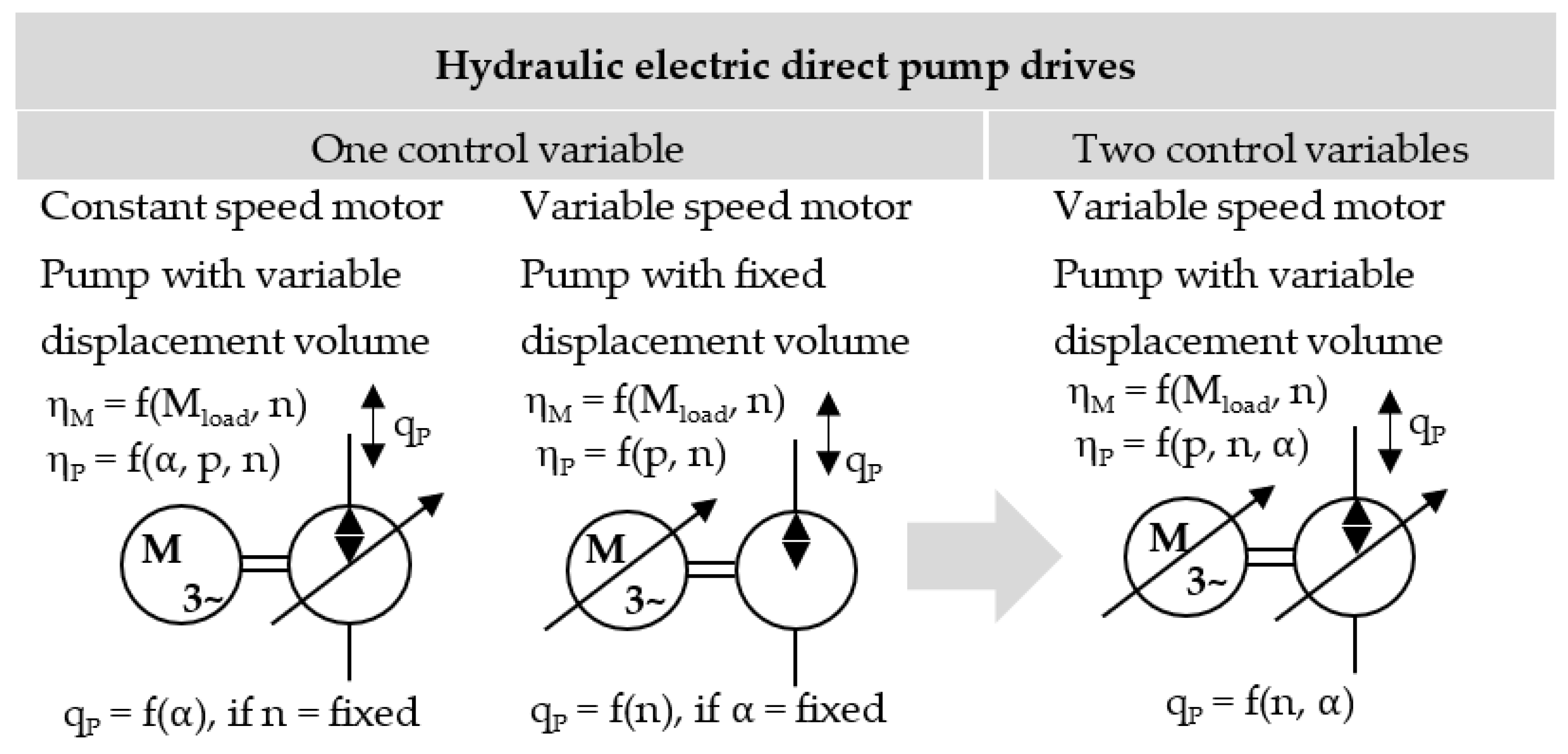
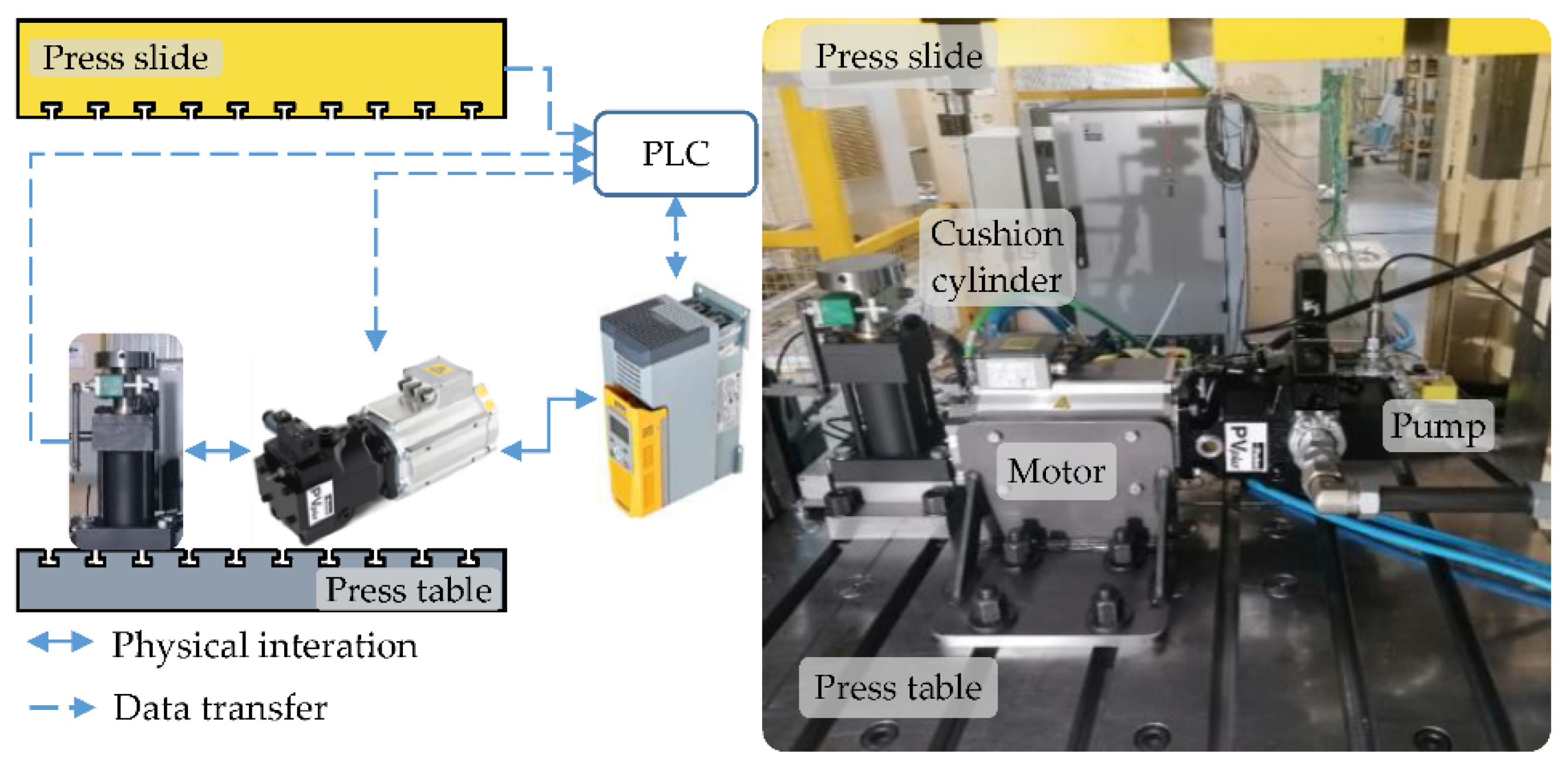
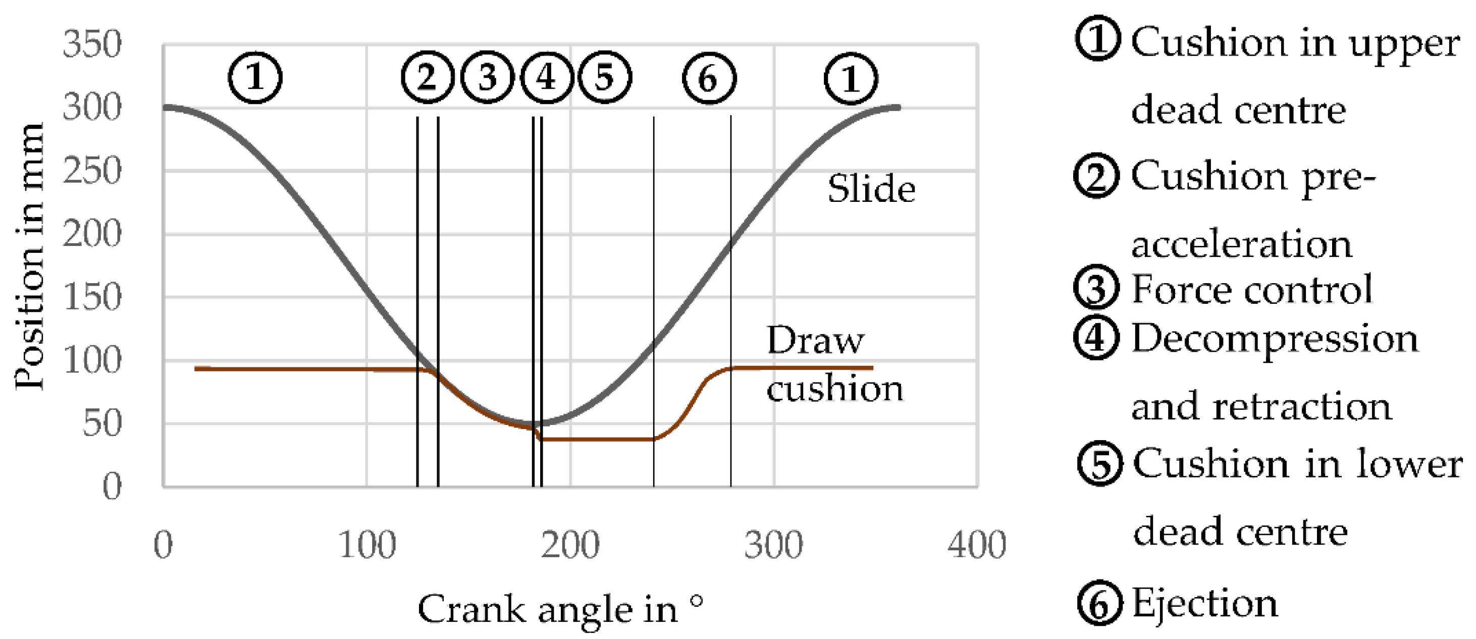
2. Implementation of a Hydraulic Drive Unit with Two Control Variables in a Drawing Cushion Application

The drive system used in the experimental setup consists of a Parker GVM servo motor and a Parker PV series axial piston pump with a variable displacement volume. The drive unit is operated with the Parker AC30 inverter which is controlled by a Beckhoff PLC for process sequencing, position, and force control. This setup results in an electrohydraulic drive unit with the two control variables of motor speed and swash plate angle to control the volume flow at the pump outlet. The drive is directly mounted to a press table, as shown in Figure 2, and provides the necessary volume flow for the cylinder, which is displaced by the slide during the stroke of the press. Using this setup, the acting forces and movements of a deep drawing sequence occurring in forming processes can be represented and the cylinder acts as a cushion cylinder in either position or force control during the drawing sequence. The drive system has a compact design for the mechanical connection of the pump to the electric motor. For this purpose, a direct form-fitting connection of the pump shaft with the male spline and the female spline shaft was implemented. Figure 2 shows the used hardware platform of the Parker drive-controlled pump (DCP). The motor type Parker GVM is a brushless synchronous servo motor with permanent magnets (PMSM). In the presented work, a motor type Parker GVM-210-150-DQW is used. The pump used in this work is an axial piston variable displacement pump of the Parker PVoc type and belongs to the Parker PV product series. The type designation “oc” stands for “over center” and refers to the pump’s ability to set both positive and negative swash plate angles. To meet the requirements of the application presented in this paper, a special design of the pump was used to run the unit in pumps as well as in motor mode.
Table 1 shows the technical details of the pump and marks the used quadrants Q1 and Q2 for the application presented in this paper. The typical sequence of a drawing cushion consists of six sections, as shown in Figure 3, where the force control during the displacement of the drawing cushion is the most critical section, as it directly influences the quality of the part produced during the deep drawing cycle during forming.

3. Model Representation of the Implemented Test Stand

The model was implemented in MATLAB® Simulink (The MathWorks, Inc., Natick, MA, USA). The press is not modeled, but included in the model as the slide movement and the contact to the cushion cylinder. The motor, is conveniently modeled in a d-q coordinate system, which rotates with the rotary field of the motor. In this representation, the voltages ud/uq and the currents id/iq, are independent of the phase angle of the rotary field. Including the transformed inductivities Ld and Lq, and the magnetic flux linkage of the permanent magnets, the differential equations can be written as:
u d = R   i d + L d d i 1 d d t ω L q i q ;   u q = R   i q + L q d i q d t ω ( L d i d + Ψ p )
The mechanical domain is represented by the equation of motion:
( J Pump + J Motor ) ω ¨ = τ Pump τ Motor
The induced torque τMotor can be calculated as follows:
τ M o t o r = 3 2 k p p ( ( L d i d + Ψ p ) i q L q i q i d )   o r   τ M o t o r K T I r m s K T 2 i q
In addition to the motor the pump induces a torque τPump on the inertia:
τ P u m p = Q + Q L e a k a g e ( ω , p , Q ) ω Δ p + τ l o s s
To fully define this equation, a representation of the actual losses of the pump due to leakage and friction is necessary. Those are obtained from experiments conducted using the actual pump. Using the regression method introduced in [11], the numerical approximations in Equation (5) are found, which are implemented in the simulation environment.
Q L e a k a g e f v o l ( ω , p , Q ) ;   τ l o s s f h m ( ω , p , Q )
The theoretical volume flow of the pump is proportional to the motor speed as well as the swash plate angle, and the pump dynamics are included in Equation (2).
The maximum dynamics of the swash plate angle and, therefore, the displacement per rotation of the pump is approximated in [11] using a linear regression function:
d α d t | m a x = α ˙ 0 + K α ( p p m i n )
Therefore, both the maximum gradient of the displacement per rotation and the volume flow is restricted, which restricts the maximum dynamics of the drive unit in the closed-loop control. The model is validated qualitatively by a matrix of experiments conducted using the test stand. The characteristics of the cushion contact force show differences that result from controller characteristics, as the stability of the swash plate angle control loop becomes unstable for aggressive control parameters. Therefore, the pre-acceleration is used to reach the desired target. Furthermore, a decompression segment became necessary in the test stand in contrast to the simulation model (see Figure 4).

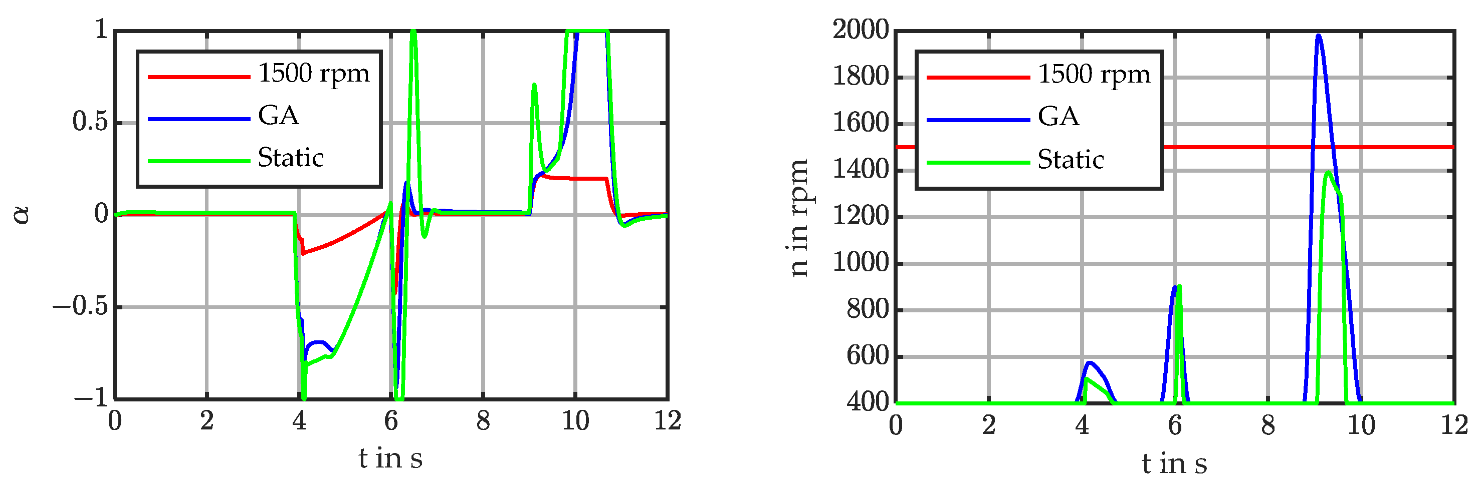
4. Energy Efficient Operation of the Drive Unit in the Drawing Cushion Application

As presented in [8], it is possible to optimize the energetic losses of the hydraulic process by utilizing the two control variables as shown in Figure 5. In contrast to VDP and SVP, the control of the SVVDP is underdetermined, as both control variables influence the volume flow. Therefore, a control distribution has to be implemented that can be used to optimize the control for certain targets, such as dynamics or energy efficiency. In this case, this is achieved by the control distribution implemented in the feedforward control. Based on the offline optimization aiming to reduce the energetic losses, the motor speed follows a defined trajectory that sets the operating point of the drive unit in motor speed and swash plate angle. With the set motor speed and the target trajectory, as well as the simplified physical properties of the system, the feedforward signal of the swash plate angle can be calculated. To compensate for modeling uncertainties, as well as disturbances, the swash plate angle is included in the closed control loop for the process parameter’s position or force, according to the current section of the process sequence.
In [8], two algorithms are implemented in Matlab® to evaluate the potential to reduce the energetic losses by applying the drive unit with two control variables. The first algorithm calculates the optimal operating point of the drive unit assuming a quasi-static operation, utilizing the known loss characteristics of both the motor and the pump. The second algorithm is a model-based approach, which uses a genetic algorithm in combination with the plant model in Simulink® to find an optimal control distribution based on a fitness function that penalizes high loss power as well as deviations from the target parameters of the process. Both algorithms result in similar trajectories for the motor speed (see Figure 6) with reduced energetic losses in the drive system (Figure 7); however, the results show that the optimization of energetic efficiency without considering the process or the dynamics of the system can result in inadmissible process deviations.
The previous considerations about the energetic properties of the drive unit and the results show that high swash plate angles and, therefore, low motor speeds are desired for an energy-optimal operation of the drive unit. A highly dynamic process requires the drive unit to be able to provide high gradients of the volume flow to respond to deviations in the closed control loop. The volume flow can be set by both control variables. Both have a maximum gradient, dependent on other process parameters. The maximum gradient of the motor speed depends on the current system pressure, as well as the limited maximum current that can be provided to the motor by the variable frequency drive, as the torque produced by the motor is proportional to the motor current (see torque Equation (3)). As described in Equation (6), the maximum gradient of the swash plate angle depends on the current system pressure. The maximum dynamic of the volume flow for the case of a constant motor speed and system pressure can be written as
d Q d t = n 60 v t h e o r d α d t .
Therefore, the maximum gradient decrease for lower motor speeds, eventually leading to insufficient dynamics for the process parameters. For example, Figure 8 shows an overshoot of the cushion contact force that is higher than the tolerance of 10% for the motor speed of 600 rpm.

5. Influence of Variation of the Control Variables on the System Dynamics

To study the influence of the variation of the motor speed on the dynamics, a series of simulations based on the Simulink model with different constant motor speeds of 1600 rpm, 1000 rpm, and 600 rpm and a cushion contact force of 55 kN is used. The sequence of the drawing process with the highest requirements on the system dynamics occurs when the press slide contacts the cushion cylinder, and the contact force is built up. Here, a maximum overshoot of <10% of the target force is desired. Furthermore, a low travel of the slide during force build-up is desired, which requires high dynamic control.
The initial overshoot of the cushion contact force is increased significantly by decreasing the motor speed, which is due to the lower maximum gradient of the volume flow, as shown in Figure 9, where, in the left diagram, the lower gradient of the volume flow can be observed during the force build-up resulting from the lower motor speed and the maximum gradient of the swash plate angle for the saturated control output |y| > 1.
The aim of the conducted simulations has been to evaluate the influence of varying the motor speed both for different constant speeds as well as dynamic variation of the motor speed on the dynamics of the system. It can be shown that, due to the modeled characteristics of the drive unit, the maximum gradients and, therefore, the maximum dynamics of the system are decreasing for lower motor speeds. As previously described, increased energy efficiency can be achieved by increasing the swash plate angle which is achieved by reducing the motor speed in partial load sequences. In this case, the position control previous to the actual drawing process is an example of a partial load sequence. This corresponds to a decrease in the maximum gradient of the volumetric flow. To ensure process parameters, the optimization of energetic efficiency should not influence the dynamics of the drive unit significantly.
Therefore, to evaluate the potential of the combined utilization of the motor speed and the swash plate angle regarding the dynamics of the system, the motor speed has been added to the control loop (see Figure 10). This approach allows for the utilization of both control variables to execute commands from the position or force controller. A reference motor speed of 600 rpm is set. The control distribution utilizes the information on the current gradient of the swash plate angle to increase the dynamics of the volume flow. This is achieved by contributing to this gradient through the acceleration or deceleration of the motor. Utilizing both control variables, this disadvantage can be compensated, which is shown in Figure 11: while the motor speed remains below the initial motor speed of 1600 rpm (see Figure 12), the characteristics of the cushion contact force show similar behavior. The fast accelerations of the motor speed to support the swash plate angle gradient contradict the initial target of energy efficiency due to high currents in the motor. Therefore, the target of energy efficiency and maintaining the process parameters can benefit from a combined approach involving energy efficiency as well as dynamics.

6. Conclusions and Outlook

In the drawing cushion application, and stationary hydraulics in general, precise force and or position control are often necessary. This requires a drive unit that is capable of high gradients of the volume flow. In this paper, an electro-hydraulic drive unit is implemented in a hydraulic drawing cushion application using available optimization algorithms to reduce the overall energy losses during the sequence. The influence of the motor speed on the dynamic system behavior has been analyzed by simulation. The simulation results show that the reduced dynamics of the volume flow due to the reduced motor speed significantly influence the control performance of the process. In order to avoid a loss of process quality, the dynamic system behavior has to be included in the considerations regarding the energy efficiency to maintain and possibly improve the system dynamics. Furthermore, the implemented combination of motor speed as well as swash plate angle as control variables for the volume flow allows for maintaining the dynamics of the system while reducing the motor speed, which is necessary for the reduction of energy losses during the process. Nevertheless, both the dynamics, as well as the energetic properties, are closely related, which motivates further research in the field of multi-criterial optimization for drive units with two control variables.

Author Contributions

Conceptualization, T.P., A.L. and R.K.; methodology, T.P., W.R.; software, W.R., T.P.; validation, T.P., W.R. and A.L.; writing—original draft preparation, W.R., R.K.; writing—review and editing, W.R.; visualization, W.R.; supervision, A.L. and S.I.; project administration, A.L., T.P. and S.I.; funding acquisition, A.L., T.P. and S.I. All authors have read and agreed to the published version of the manuscript.

Funding

Public funded SAB project: 100356054. This project is funded by the European Union from the European Regional Development Fund within the framework of the EFRE “Europe funds Saxony”. This project is co-financed by tax funds based on the budget adopted by the members of the Saxon federal state parliament.

Institutional Review Board Statement

Not applicable.

Informed Consent Statement

Not applicable.

Data Availability Statement

Not applicable.

Conflicts of Interest

The authors declare no conflict of interest.

Abbreviations/Symbols

VariableDescriptionUnit
id/qd/q-axis current[A]
JInertia[kgm2]
kppPole pairs[-]
KdViscous friction torque loss[Nm/(1000 rpm)]
Regression parameter[1/(Pa·s)]
LInductance[mH]
nRotational speed[rpm]
pPressure[bar]
QVolume flow[m3/s]
RPhase resistance[Ω]
TFDry friction torque loss[Nm]
Ud/qd/q-axis voltage[V]
αRelative pump swash plate angle[-]
ΨpFlux linkage of permanent magnets[-]
ωAngular velocity[1/s]
τTorque[Nm]

References

  1. Kurth, R.; Tehel, R.; Päßler, T.; Putz, M.; Wehmeyer, K.; Kraft, C.; Schwarze, H. Forming 4.0: Smart machine components applied as a hybrid plain bearing and a tool clamping system. Procedia Manuf. 2019, 27, 65–71. [Google Scholar] [CrossRef]
  2. Alaluss, M.; Drechsler, C.; Kurth, R.; Mauersberger, A.; Ihlenfeldt, S.; Marré, M.; Labs, R. Usage-based leasing of complex manufacturing systems: A method to transform current ownership-based into pay-per-use business models. Procedia CIRP 2022, 107, 1238–1244. [Google Scholar] [CrossRef]
  3. Schenke, C.; Weber, J. Steigerung der Energieeffizienz Verdrängersteuerung senkt den Energiebedarf hydraulischer Tiefziehpressen. O+P Fluidtechnik 2019, 62, 54–59. [Google Scholar]
  4. Willkomm, J.; Wahler, M.; Weber, J. Process-Adapted Control to Maximize Dynamics of Speedand Displacement-Variable Pumps. In Proceedings of the ASME/BATH 2014 Symposium on Fluid Power and Motion Control, Bath, UK, 10–12 September 2014. [Google Scholar] [CrossRef]
  5. Gao, M.; Li, X.; Huang, H.; Liu, Z.; Li, L.; Zhou, D. Energy-saving Methods for Hydraulic Presses Based on Energy Dissipation Analysis. Procedia CIRP 2016, 48, 331–335. [Google Scholar] [CrossRef] [Green Version]
  6. Huang, H.; Jin, R.; Li, L.; Liu, Z. Improving the Energy Efficiency of a Hydraulic Press Via Variable-Speed Variable-Displacement Pump Unit. ASME J. Dyn. Sys. Meas. Control. 2018, 140, 111006. [Google Scholar] [CrossRef]
  7. Jin, R.; Huang, H.; Li, L.; Zhu, L.; Liu, Z. Energy Saving Strategy of the Variable-Speed Variable-Displacement Pump Unit Based on Neural Network. Procedia CIRP 2019, 80, 84–88. [Google Scholar] [CrossRef]
  8. Reichert, W.; Leonhard, A.; Päßler, T.; Gummich, C. Energy efficient operation of a hydraulic drive unit with two degrees of freedom in a hydraulic drawing cushion. In Proceedings of the 13th International Fluid Power Conference, Aachen, Germany, 13 February 2022. [Google Scholar]
  9. Landgrebe, D.; Blau, P.; Päßler, T.; Tehel, R.; Voigt, T. Energieoptimierte Antriebskonzepte für hydraulische Umformmaschinen mit elektrischen Servoantrieben; Europäische Forschungsgesellschaft für Blechverarbeitung e.V.: Hannover, Germany, 2016. [Google Scholar]
  10. Neubert, T. Energie sparende Hydraulikantriebe-Drehzahlveränderbarer Verstellpumpenantrieb in Spritzgießmaschinen; Carl Hanser Verlag: München, Germany, 2002. [Google Scholar]
  11. Willkomm, J. Modellprädiktive Optimierung drehzahlvariabler Verstellpumpen. Ph.D. Thesis, TU Dresden, Dresden, Germany, 2016. [Google Scholar]
  12. Doege, E.; Behrens, B.A. Blechumformung. In Handbuch Umformtechnik; Springer: Berlin/Heidelberg, Germany, 2016. [Google Scholar] [CrossRef]
Figure 1. Hydraulic pump drives with one and two degrees of freedom to vary volume flow.
Engproc 26 00018 g001
Figure 2. Hardware platform Parker drive-controlled pump.
Engproc 26 00018 g002
Figure 3. Scheme and sequence of the drawing process according to [12].
Engproc 26 00018 g003
Figure 4. Cushion contact force and position at 1600 rpm and contact force of 55 kN from experiment and simulation.
Engproc 26 00018 g004
Figure 5. Schematic representation of the implementation of the drive unit with two control variables and offline optimization for the control variable distribution.
Engproc 26 00018 g005
Figure 6. Left: motor speed trajectories generated by the optimization algorithms; right: resulting swash plate angles during the sequence.
Engproc 26 00018 g006
Figure 7. Energy losses for SVVDP with both optimization strategies and VDP at 1500 rpm.
Engproc 26 00018 g007
Figure 8. Cushion contact force for different motor speeds (simulation).
Engproc 26 00018 g008
Figure 9. Volume flow and swash plate angle for different motor speeds during force build-up.
Engproc 26 00018 g009
Figure 10. Schematic representation of the control variable distribution for maximal dynamics.
Engproc 26 00018 g010
Figure 11. Comparison of the cushion contact force for different constant motor speeds and the combined speed and swash plate angle control, cushion contact force 55 kN.
Engproc 26 00018 g011
Figure 12. Motor speed and swash plate angle for a simulation with constant motor speed and the combination of motor speed and swash plate angle, cushion contact force 55 kN.
Engproc 26 00018 g012
Table 1. Technical details of the hydraulic pump.
Properties Pump Parker PVoc 040
Max. displacement40 cm³/rev
Swash angle (max/min)+/−100%
Output flow at 1500 rpm60 l/min
Nominal pressure350 bar
Max. pressure (at 20% working cycle)420 bar
Max. speed (preferred/reverse rotation direction)2900/2700 rpm
Control valve (proportional directional valve)Parker D1FP
Publisher’s Note: MDPI stays neutral with regard to jurisdictional claims in published maps and institutional affiliations.

