Abstract
Press hardening is used to produce complex parts by hardening them in a die. This results in martensitic structures with high strength values but low ductility. However, for real components, the combination of places with high strength or high ductility is required. One possibility is using a combined tool (i.e., tailoring methods) instead of joining parts by welding or gluing. Therefore, this work was focused on the construction and design of a partly heated and partly cooled tool for press hardening. This makes it possible to process high-strength steels and achieve different mechanical properties at different points in the stamping. To achieve intensive cooling, part of the tool was made by 3D printing, making it possible to create effective cooling channels in the functional part of the tool. The second part of the tool was heated by heating cartridges. FEM in DEFORM software was used to lay out the heating cartridges and cooling channels. The tool was successfully installed on a hydraulic press, including the first tests to achieve omega profiles with different mechanical properties.
1. Introduction
High-strength steels (AHS) are widely used in the automotive industry. Their volume has increased in the last few years (Figure 1) as manufacturers try to improve crash safety and reduce weight.
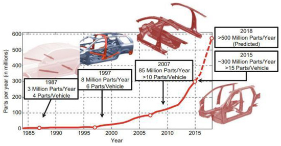
Figure 1.
The growing popularity of hot stamping over time (complexity of parts and production volume) [1].
Parts such as B-pillars, A-pillars, side-impact reinforcement beams, bumpers, and many other components are manufactured using AHS steels in the hot stamping process [1]. It is usually necessary to achieve different properties at the top and bottom of the parts of these components. For this reason, attention is beginning to focus on the development of combined tools consisting of a heated and a cooled part, which allows different properties in AHS steels to be achieved [2,3]. By processing AHS steels using press hardening in a combined tool, we can achieve different mechanical properties within a single part. This can to some extent replace the method of welding two or more sheets of different materials, possibly different thicknesses (i.e., tailor-welded blanks) that have been used up to now [2], or the use of varying degrees of austenitization in different areas of the semifinished product by using different heating temperatures [4].
At the same time, press hardening achieves high productivity and low time consumption, which is a prerequisite for the automotive industry. Figure 1 shows the growing popularity of the process in the automotive sector, both in terms of the complexity of the parts produced and the volume of production.
Several issues arise when using a combined tool which is associated with combined heating and cooling in one tool. These problems were differently addressed by different authors. Meza-García et al. investigated the thermomechanical processing of aluminium alloy AA6082 in a similar tool. They used a segmented die to produce a side-sill component for a car chassis. The tool consists of a punch (upper tool) and a die (lower tool). Each part of the tool has two halves, a cooled half and a heated half. It is heated by heating elements and cooled by water. There are insulation plates between the tool and the clamping plate. All water distribution channels were made by drilling [5]. Hoffmann et al. also used drilling for a cooling system. They used diameters of holes from 8 to 16 mm. Sealing plugs were used because of the technology of drilling [6]. Schieck et al. evaluated three cooling concepts and their advantages and disadvantages. Drilled cooling channels have a good cooling capability, but sealings must be used and it is not possible to produce complicated geometries. A shell structure has good cooling capability even for complicated component geometries, but it is expensive to produce. Cast-in cooling channels are good for complex geometries and do not have a problem with sealing, but in terms of the material used (cast iron) are difficult to repair, and also have a lower cooling capacity [7].
Most of the problems are related to the cooled part, especially the cooling channels. These channels must allow the supply of coolant to critical areas and must not make the tool more expensive and, above all, longer to produce. Another problem is the temperature to which the tool can be heated, which is higher for high-strength steels than for aluminium alloys [5], or to temperatures around 400 °C [4]. However, e.g., for modern third-generation steels, which can achieve higher ultimate strength values than 22MnB5, it is necessary to heat the tool to a higher temperature [8,9]. Goerge R. et al. also addressed the placement of heating cartridges in a direction perpendicular to the formed part [10], which led to uneven heating of the tool and the requirement for more heating cartridges.
Taking these pros and cons into consideration, we decided to produce a combined tool that eliminates the disadvantages. As a result, a tool with a higher heating temperature, and additively manufactured cooled parts were chosen. The proposed combined tool should be the second generation of the omega profile tool for press hardening in our laboratory. The first tool was smaller and consisted of only a heated part with an omega profile shape. In this tool, it was possible to insert sheets of 140 × 140 mm. The influence of the process on high-strength steels with higher ductility values [11], the influence of forming temperature on materials DOCOL PHS 1800 and 2000 steels [12], the use of TRIP steels [13], the influence of chromium and niobium on TRIP steels [14], and physical simulation [15] were investigated using this tool.
In the second generation of the combined tool, it will be possible to perform various heat treatments in one operation on one sheet and to compare the changes in mechanical properties and resulting structures in terms of uniform processing parameters for a single sheet. The benefit is therefore timesaving in obtaining different properties within a single sheet. We specifically want to focus on the processing of modern multiphase high-strength steels, as we can reach temperatures of up to 750 °C using heating cartridges and also intensively cool the 3D-printed parts of the tool.
2. Experimental Details
A split press-hardening tool had to be developed to process modern types of high-strength steels and create different mechanical properties in different regions of shaped parts. The split tool should consist of a heated part and a cooled part.
The tool was mounted on a hydraulic press with a force of 100 tons. The geometry of the tool was influenced not only by the force of the hydraulic press but also by the spacing of the frame columns of the press. To simplify the production of the tool and the subsequent analysis of the results, an omega profile was chosen. Another limiting factor was the size of the input sheet. It was expected that, in addition to conventional steels, experimental steels, whose chemical composition is being designed at Regional Technological Institute (RTI), will be processed in this tool. These steels were cast in the form of small ingots weighing between 50 and 250 kg, from which sheets are subsequently prepared by rolling. Due to the shape of the ingot and the capabilities of the rolling mill, we were limited by the maximum strip width we were able to obtain. Based on all these factors, a sheet metal blank of 240 × 210 mm was proposed as the optimum size for the tool.
3. Combined Tool Design
The upper and lower parts of the tool consisted of a heated and a cooled part, which were firmly connected. As the heated and cooled parts should not come into contact with each other, insulating plates were used. Clamping plates were inserted between the hydraulic press and the upper and lower parts of the tool. The complete assembly is shown in Figure 2. These plates performed two functions. First, they served to hold the entire tool in position and attached the entire assembly to the hydraulic forging press. They were also used as protective plates between the tool and the upper and lower part of the press to prevent it from overheating when the tool section is heated.
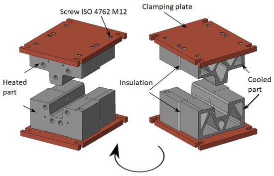
Figure 2.
Assembly of the CAD model of the combined tool.
The heating of the tool section was carried out by heating cartridges and the temperatures were measured and regulated by thermocouples placed at various points in the tool. In the cooled part, rapid heat dissipation must be achieved during quenching in the tool, which was accomplished by using cooling channels for coolant distribution.
Several design options were considered for the production of the cooled part of the tool. The first option is to drill channels in the solid material. This usually involves drilling in multiple directions and requires the use of plugs to terminate the holes. The second option is to manufacture the tool by casting. This involves casting a pre-prepared tubular skeleton with molten metal. The advantage is the possibility of creating more complex shapes and eliminating the threat of leaks. However, the possibilities of using this material are limited. Another option is additive manufacturing (AM) by metal 3D printing. Due to the advantages of additive technologies, this option was chosen for the production of the cooled part. AM brings material savings and great possibilities in terms of design freedom [1,16]. In our case, we used an EOS M290 3D printer working on the principle of DMLS (Direct Metal Laser Sintering) using MS1 powder technology. The heated part was made of tool steel ČSN 19 573 (i.e., X153CrMoV12). Initially, CAD models of all the components were created to assemble a model of the overall combined tool.
During the design of the models for 3D printing, the models underwent topological optimization to save as much material as possible while maintaining the required properties of the press-hardening tool. In addition, the lightweight structure of the printed tool and thus lower heat transfer to the cooled half from the clamping plate was achieved.
As can be seen from Figure 2, the cooled (printed) part was narrower than the heated part (230 versus 250 mm). This was due to the limited working area when printing these parts. However, the geometry of the stop was maintained and designed so that the samples were always in the same position when the sheet is fed into the tool. The stop was a raised groove on the bottom of the tool (labeled in Figure 3). This stop must be reflected on the top of the tool in the form of a relief (Figure 4). The internal cooling channels were designed in the shape of a large “U” with separate inlets and outlets for each channel. The channels were arranged over the entire surface of the tool that comes into contact with the formed sheet metal, including the omega profile, (see the diagram in Figure 5).
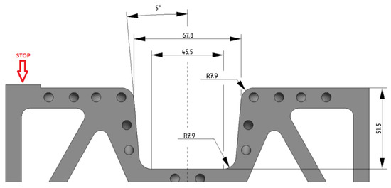
Figure 3.
Lower part of the cooled part of the tool.
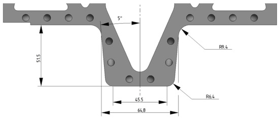
Figure 4.
Upper part of the cooled part of the tool.
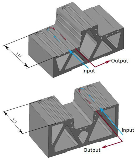
Figure 5.
Cut view of the cooling system of the cooled tool.
The cooling system was designed as a discontinuous circuit, so that cold water is used for cooling at all times and heated water is taken out of the circuit. This ensured both a constant cooling rate of the formed part and rapid cooling of the tool itself. This prevented the tool from heating up and allowed forming to be carried out in a rapid stroke without affecting the cooling rate.
In addition to the depth of the omega profile, suitable radii of curvature on the upper and lower parts of the omega profile and wall chamfers on both parts of the tool had to be chosen. Appropriately chosen radii reduce the risk of material failure during forming [17,18]. In general, when a steel plate is used, the radii should be between five and ten times the thickness of the plate. In the case of aluminium alloys, it is more likely to be ten times the thickness of the plate. Here, the thickness was 1.5 mm, hence the choice of the values shown in Figure 3 and Figure 4.
4. Simulation
The tool was designed for forming rectangular sheets with dimensions 210 × 240 mm and a thickness of 1.5 mm.
The actual production of the tool was preceded by a simulation using the finite element method (FEM) of the press hardening in DEFORM (Design Environment for FORMing). The numerical simulations aimed to predict the possible behavior of a real experiment. We wanted to eliminate possible problem areas, and determine the heat conduction throughout the tool, functionality in terms of forming, thermal effects, etc. The simulation parameters were chosen to be as close as possible to the expected conditions of the real experiment. The sheet material chosen for the simulations was 22MnB5 with a tool heating temperature of 425 °C. The Ms temperature for this material was 411 °C [19].
An example of one of the simulations of heat conduction to the cooled half of the tool through the clamping plate is shown in Figure 6. It can be seen that, due to the printed structure of the tool, heating reached a maximum of 86.2 °C in the lower part of the tool, while the temperature remained around 20 °C in the area intended for forming. This phenomenon was also measured during the testing. The temperatures measured by a thermal camera differed from the simulation by a maximum of 8%.
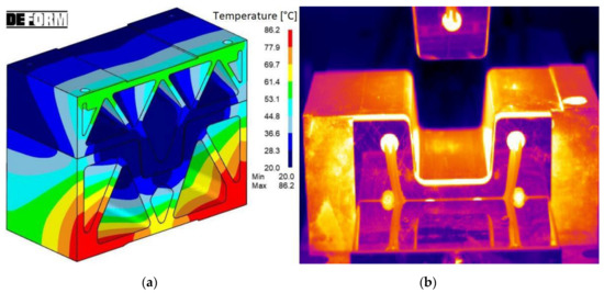
Figure 6.
(a) Heat conduction to the cooled half of the tool and (b) thermal camera measurement image (heated part in the front, and cooled part in the back).
5. Production, Assembly, and Testing
After printing the cooled part of the tool with MS1 material, the tool was subjected to heat treatment in a protective argon atmosphere to reduce internal stresses. The processing consisted of heating to 820 °C with a dwell time of 1 h and aging at 490 °C for 6 h [20,21].
Afterward, the printed parts were cut off from the platform and taken to the machining site where the final functional surface was milled, threads were cut, etc. This was followed by the assembly of all the parts onto the clamping plates, thus maintaining the relative position of the cooled and heated parts of the tool throughout the press-hardening process. First, the heated parts of the tool (heavier because they are solid) were clamped with the final surface condition already milled. In addition, grooves were cut into the heated tool parts to place thermocouples for subsequent measurement of the temperature distribution during the process itself. These grooves were milled to a depth such that the thermocouples were at a sufficient depth below the surface to measure the prescribed requirements. The thermocouples were K-type insulated thermocouples with a diameter of 1.5 mm. Insulating plates made of PAMITHERM 41130 thermally insulating laminate material were attached to the edge that would subsequently be connected to the cooled part of the tool. The printed parts of the tool were then attached.
Once all the parts of the tool were assembled, HHP stainless steel heating cartridges with a diameter of 20 mm and a length of 125 mm, capable of reaching temperatures of up to 750 °C, were inserted into the holes of the heated part of the tool. Three cartridges were in the upper part of the tool and four were in the lower part, these were connected to a heating source with PID controllers.
Threaded brass hose tails were screwed onto the cooled parts of the tool and the hoses were then pulled onto them. The hoses of the coolant inlet and outlet had different diameters. The hoses for draining the fluid from the tool had to have a higher temperature resistance, as they are expected to be hot. The cooling system was also completely interconnected with the cooling system in the clamping plates of the press to prevent heat transfer from the heated part of the tool to the press. The entire system was regulated by ball valves for the inlet and outlet of water. As there were a total of 28 holes in the cooled tools (14 inlets and 14 outlets), two aluminium alloy distribution blocks were also made to distribute the water and eliminate excess hose length.
Once the tool was installed in the hydraulic press, including the cooling and heating system, the first functional tests were carried out. After the first tests, it was necessary to reseal the hose tails and hose connections. Furthermore, adjustments were made to the press range, tool clamping, and fine-tuning of the heating of the tool part. After all the tests and checks, the tool was ready for press hardening different materials with varying processing parameters.
Figure 7 shows the complete tool set-up including accessories at the workplace of the CKW 6000 hydraulic forging press. The combined tool is shown in the picture from the side where the heating took place. On this side were the boxes in which the supply line from the power supply was connected to the individual heating cartridges. Thermocouples were then routed from this side to the data logger for measuring temperatures during the operation. The power source with PID controllers and a diagram of the thermocouple locations can also be seen. Only the cooling in the clamping plate of the press is seen here to avoid overheating the device.
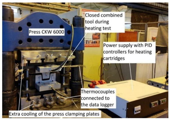
Figure 7.
Combined tool during heating test.
6. Results
The result of the functional tests and parameter tuning was a graph obtained by the thermocouples which recorded the heating of the tool (Figure 8). The graph shows the recordings from thermocouples TM 1, 3, 5, and 6 for the upper part of the tool and TM 8, 9, 10, 11, and 12 for the lower part of the tool. Thermocouples 2 and 7 were fed to a power supply with PID controllers and used to reheat the tool (switching the heating on and off) if necessary. This effect is visible on the graph at a time of about 2000 s, where the waveforms are visible due to the switching. From the measurements, it can be said that heating to a tool temperature of 425 °C takes approximately 30 min.
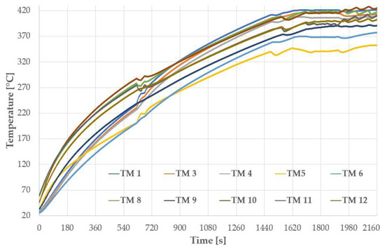
Figure 8.
Heating test curves measured by thermocouples.
In comparison with the results of the simulation, where points at the contact plate of the tool reached temperatures from 414 to 424 °C in 30 min (1800 s) from the start of the heating, in the experiment, TM5 and TM6 (Figure 8) showed lower temperatures than they should have. This was solved by deepening the holes for mounting the thermocouples. After this modification, the temperatures were also around 420 °C. The temperatures after 30 min in both the simulation and the experiment are very similar.
Figure 9 shows the difference in the temperature distribution between the simulation and the experiment. The width of the transition area depends on the dwell time of the sheet in the combined tool. Figure 9a shows an optimum variant of the temperature distribution in DEFORM after a dwell time of 60 s in the tool, and Figure 9b shows an image from a thermal camera with temperatures from 20 °C to approximately 425 °C with the same dwell time. The first experiments showed that it is possible to produce omega profiles without visible defects with a different temperature field distribution along the length of the sheet, as seen in Figure 9c.
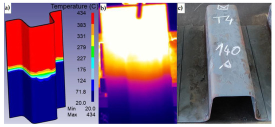
Figure 9.
(a) Temperature distribution in DEFORM, (b) temperature distribution during the experiment, and (c) final shape of the sheet.
7. Conclusions
The aim was to produce a combined tool for testing different materials suitable for this application and to vary the parameters to achieve the optimum settings for each material. The actual design and optimization of the tool progressed from the initial CAD design, through topological optimization for 3D printing, machining, assembly of the entire tool, wiring of the necessary components for the functionality of the assembly, to the actual tuning of the function of all the components.
An advantage of this combined tool is the control of the heating temperature by a PID controller power supply, to which a single control thermocouple is connected from both the upper and lower heated parts of the tool, according to which the power supply regulates the temperature of the heating cartridges. On the cooling fluid side, control is achieved using ball valves and distribution blocks.
Moreover, thanks to the thermocouples inside the tool, it is possible to monitor the entire press-hardening process from the heating of the tool, through the effect of the tool heating after the insertion of the sheet metal, to the cooling in the tool. This will subsequently allow a better description of the mechanisms taking place in the materials during this process.
The fabrication was preceded by verification of the tool functionality using the DEFORM simulation program.
Author Contributions
Conceptualization, F.V., H.J. and J.V.; methodology, H.J.; software, M.W.; validation, F.V. and H.J.; investigation, J.S.; resources, F.V.; data curation, M.W.; writing—original draft preparation, F.V.; writing—review and editing, F.V.; visualization, F.V.; supervision, H.J.; project administration, F.V.; funding acquisition, F.V. All authors have read and agreed to the published version of the manuscript.
Funding
This article was created with the financial support of the project Improving the Quality of Internal Grant Schemes at the UWB, project registration number: CZ.02.2.69/0.0/0.0/19_073/0016931. The present contribution has been prepared with the support of the student grant competition of the University of West Bohemia, SGS-2021-030 “Development of new materials, application of modern methods of their processing, ecological production, welding, and testing”. The project was funded from specific resources of the state budget for research and development.
Institutional Review Board Statement
Not applicable.
Informed Consent Statement
Not applicable.
Data Availability Statement
The raw data are not publicly available due to ongoing research.
Acknowledgments
We also wish to thank the native speaker, Jeremy M. King, for editing the English language and style.
Conflicts of Interest
The authors declare no conflict of interest.
References
- Billur, E. Hot Stamping of Ultra High-Strength Steels: From a Technological and Business Perspective; Springer: Cham, Switzerland, 2019; ISBN 978-3-319-98868-9. [Google Scholar]
- Mori, K.-I.; Bariani, P.; Behrens, B.-A.; Brosius, A.; Bruschi, S.; Maeno, T.; Merklein, M.; Yanagimoto, J. Hot stamping of ultra-high strength steel parts. CIRP Ann. 2017, 66, 755–777. [Google Scholar] [CrossRef]
- Nakagawa, Y.; Mori, K.-I.; Suzuki, Y.; Shimizu, Y. Tailored tempering without die heating in hot stamping of ultra-high strength steel parts. Mater. Des. 2020, 192, 108704. [Google Scholar] [CrossRef]
- Wang, K.; Zhu, B.; Wang, L.; Wang, Y.; Zhang, Y. Tailored properties of hot stamping steel by resistance heating with local temperature control. Procedia Manuf. 2018, 15, 1087–1094. [Google Scholar] [CrossRef]
- Meza-García, E.; Rautenstrauch, A.; Leonhardt, A.; Kräusel, V.; Landgrebe, D. Forming with Thermomechanical Treatment for Manufacturing a Side Sill Demonstrator of AA6082 Aluminium Sheet Alloy. In Proceedings of the 6th International Conference Hot Sheet Metal Forming of High-Performance Steel CHS2, Atlanta, GA, USA, 4–7 June 2017; ISBN 978-1-935117-66-7. [Google Scholar]
- Hoffmann, H.; So, H.; Steinbeiss, H. Design of Hot Stamping Tools with Cooling System. CIRP Ann. 2007, 56, 269–272. [Google Scholar] [CrossRef]
- Schieck, F.; Hochmuth, C.; Polster, S.; Mosel, A. Modern tool design for component grading incorporating simulation models, efficient tool cooling concepts and tool coating systems. CIRP J. Manuf. Sci. Technol. 2011, 4, 189–199. [Google Scholar] [CrossRef]
- Li, Z.; Ding, H.; Cai, Z. Mechanical properties and austenite stability in hot-rolled 0.2C–1.6/3.2Al–6Mn–Fe TRIP steel. Mater. Sci. Eng. A 2015, 639, 559–566. [Google Scholar] [CrossRef]
- Yang, F.; Luo, H.; Hu, C.; Pu, E.; Dong, H. Effects of intercritical annealing process on microstructures and tensile properties of cold-rolled 7Mn steel. Mater. Sci. Eng. A 2017, 685, 115–122. [Google Scholar] [CrossRef]
- George, R.; Bardelcik, A.; Worswick, M. Hot forming of boron steels using heated and cooled tooling for tailored properties. J. Mater. Process. Technol. 2012, 212, 2386–2399. [Google Scholar] [CrossRef]
- Jirková, H.; Opatová, K.; Jeníček, Š.; Kučerová, L. Press Hardening on High-Strength Steels with Higher Ductility Values. In Proceedings of the 8th International Conference Hot Sheet Metal Forming of High-Performance Steel CHS2, Barcelona, Spain, 30 May–2 June 2022; ISBN 978-3-95735-150-0. [Google Scholar]
- Opatová, K.; Jirková, H.; Holá, M.; Jeníček, Š. Influence of Forming Temperature and Partitioning on Properties of Steels for Press-Hardening. In Proceedings of the 8th International Conference Hot Sheet Metal Forming of High-Performance Steel CHS2, Barcelona, Spain, 30 May–2 June 2022; ISBN 978-3-95735-150-0. [Google Scholar]
- Jirková, H.; Vrtáček, J.; Peković, M.; Janda, T.; Kučerová, L. Influence of Chromium and Niobium on the Press-Hardening Process of Multiphase Low-Alloy TRIP Steels. Mater. Sci. Forum 2021, 1016, 636–641. [Google Scholar] [CrossRef]
- Jirková, H.; Opatová, K.; Jenicek, S.; Vrtáček, J.; Kučerová, L.; Kurka, P. Use of multi-phase trip steel for press-hardening technology. Acta Met. Slovaca 2019, 25, 101–106. [Google Scholar] [CrossRef]
- Jirková, H.; Opatová, K.; Wagner, M.F.; Mašek, B. Physical Simulation of Press Hardening of TRIP Steel. In Proceedings of the International Conference on Martensitic Transformations: Chicago; The Minerals, Metals & Materials Series; Stebner, A., Olson, G., Eds.; Springer: Cham, Switzerland, 2018. [Google Scholar]
- Chantzis, D.; Liu, X.; Politis, D.J.; El Fakir, O. Review on additive manufacturing of tooling for hot stamping. Int. J. Adv. Manuf. Technol. 2020, 109, 87–107. [Google Scholar] [CrossRef]
- Taylan, A.; Tekkaya, A.E. Sheet Metal Forming: Fundamentals; ASM International: Novelty, OH, USA, 2012; ISBN 978-1-61503-842-8. [Google Scholar]
- Szumera, J.; Szumera, J.A. The Metal Stamping Process: Your Product from Concept to Customer; Industrial Press: New York, NY, USA, 2003; ISBN 0-8311-3164-0. [Google Scholar]
- Min, J.; Lin, J.; Li, J. Effect of Deformation Temperature on the Microstructure of Boron Steel 22MnB5. Adv. Sci. Lett. 2011, 4, 938–942. [Google Scholar] [CrossRef]
- Kučerová, L.; Zetková, I.; Jandová, A.; Bystrianský, M. Microstructural characterisation and in-situ straining of additive-manufactured X3NiCoMoTi 18-9-5 maraging steel. Mater. Sci. Eng. A 2019, 750, 70–80. [Google Scholar] [CrossRef]
- Kučerová, L.; Burdová, K.; Jeníček, Š.; Chena, I. Effect of solution annealing and precipitation hardening at 250 °C–550 °C on microstructure and mechanical properties of additively manufactured 1.2709 maraging steel. Mater. Sci. Eng. A 2021, 814, 141195. [Google Scholar]


Publisher’s Note: MDPI stays neutral with regard to jurisdictional claims in published maps and institutional affiliations. |
© 2022 by the authors. Licensee MDPI, Basel, Switzerland. This article is an open access article distributed under the terms and conditions of the Creative Commons Attribution (CC BY) license (https://creativecommons.org/licenses/by/4.0/).