1. Introduction
Motion platforms are used in flight and driving simulations to imitate a real sense of motion. For example, they reproduce the accelerations and rotation rates that act on a person in a car or an aircraft. Thus, they play an essential role in pilot training and vehicle development. Further motion platforms are used in perception research and for spatial disorientation training. Another field of application is testing the dynamic behavior of mechanical structures or fluids.
Motion platforms come in many different types, all of which have advantages and disadvantages. The majority of motion platforms are based on Stewart platforms [
1]. A Stewart platform consists of two frames, where the lower frame is firmly anchored to the ground and the upper frame can move freely in space. The two frames are connected by six linear actuators with ball joints and universal joints. There are three attachment points on both frames, to each of which two linear actuators are attached. Since the attachment points of the lower and upper frames are arranged in a triangle and shifted by 180 degrees to each other, this results in a very rigid system. Usually, a cabin is mounted to the upper frame, where a pilot can take a seat. However, the platform’s workspace, both translational and rotational, is heavily constrained by the reach of the linear actuators. For example, extensive roll maneuvers are not possible because the robot cannot turn the platform overhead.
Motion platforms based on industrial robots are designed to overcome this problem [
2]. The advantage of a six-axis robot over a Stewart platform is a larger workspace, whereby the rotational workspace especially is considerably larger. A Stewart platform, on the other hand, has higher stiffness and allows a higher payload at a comparable size. Some motion platforms extend the Stewart platform with additional linear axes [
3,
4] and an additional rotational axis [
5] to increase the workspace. This work discusses a novel motion platform based on a Stewart platform on which two additional rotational axes are mounted. The platform concept was initially presented in [
6]. As a result, the platform has high stiffness and the rotational workspace is extended to be similar to that of an industrial six-axis robot. After the motion platform, a method is presented to determine the maximum torque expected in the two additional axes in a worst-case scenario. This torque is required for the design and selection of the drives used in the rotational axis. Further, this method allows us to determine the maximum moment or the maximum force at a certain point on a structure in a certain direction, which can be used as external moments and forces in a stress analysis.
2. Novel Motion Platform
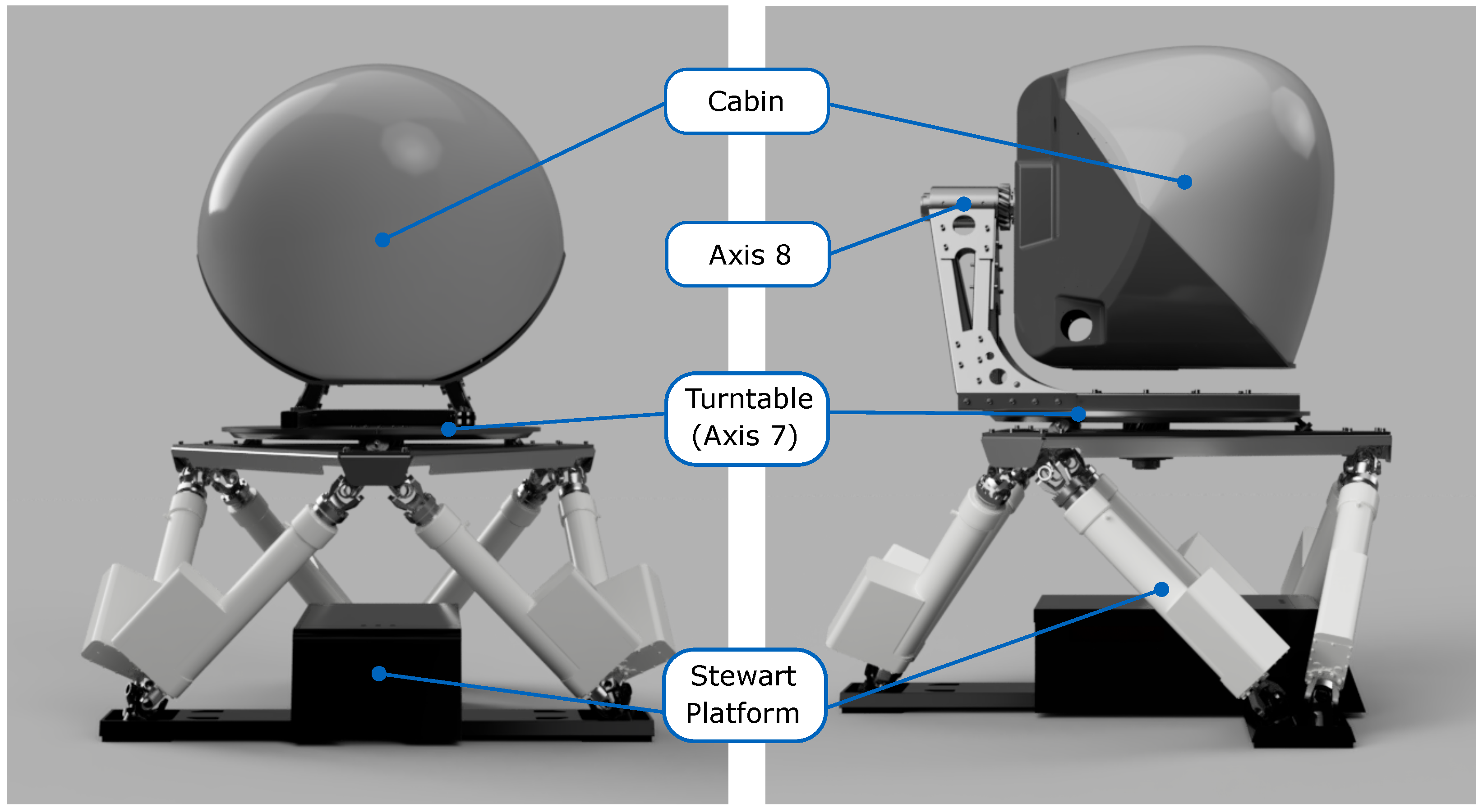
Figure 1 shows a scheme of the novel motion platform in front and side views. The basis is formed by a Stewart platform, which is extended by two additional axes. A turntable, which represents axis 7, is mounted directly on the Stewart platform and allows for endless rotation in the yaw axis. Axis 8 is mounted onto a screw structure and is arranged perpendicular to axis 7, allowing an endless roll rotation. There are slip rings in both axes for current and data supply. The axes are driven by a motor–gearbox combination that provides the required torques and holding forces. On top of axis 8, a cabin is mounted, in which a pilot can be seated. The same cabin is already used in the DLR Robot Motion Simulator [
2].
3. Methods
To choose suitable motors for the two additional axes, the desired rotational speed and the maximum motor torque need to be known. While the rotational speed can be chosen as desired, the maximum torque must be calculated. Therefore, a desired angular acceleration is required. In common methods for motor sizing, the root mean square (RMS) Torque or RMS Power is used as a measure to avoid overheating of the motor. In the case of the motion platform, however, the maximum torque is many times greater than the RMS torque and the duty cycle is low. Thus, overheating is not a critical design criterion in this application.
The simplest way of calculating the maximum motor torque
is to multiply the desired angular acceleration
with the mass moment of inertia
I and add the load torque
:
The mass moment of inertia I includes the inertia of the motor, the gear, and all parts which are connected to the axis. The load torque results from gravity and friction forces. This method is commonly used in applications with a single actuator, such as an elevator, or to estimate the motor torque in more complicated systems with low dynamics. For motors that are connected to an actuated base, such as an industrial six-axis robot or a Stewart platform, this method of calculating the torque is not sufficient. Additional torques resulting from the movement of the base need to be considered.
The motors of the two additional axes should be sized to provide sufficient torque, regardless of the Stewart platform’s movements. A multibody simulation model of the machine needs to be used to represent the influence of all motors on each other. With the help of the model, an optimization problem can be formulated, which takes into account the position, velocity and acceleration limits of all motors:
By varying the motor positions or joint angles , a trajectory was determined at which the objective function , which describes a torque, becomes maximum. The torque was calculated with the help of the multibody simulation model and represents, e.g., the torque in the seventh or eighth axis. When solving the optimization problem, all motors started and stopped at a certain configuration and all motors were at rest at and . The maximum velocity and the maximum acceleration of all motors were taken into account, as well as the position limits and of the Stewart platform motors.
The programming language Modelica was used to set up and solve the optimization problem as well as to model the multibody system. Modelica is an object-oriented programming language for modeling dynamic systems, allowing textual and visual programming [
7]. The simulation model of the platform was based on the Modelica MultiBody Library, which is part of the Modelica Standard Library. To solve the optimization problem, a optimization library for interactive multi-criteria optimization tasks was utilized [
8]. In combination with the Modelica multibody model, it is possible to perform an optimization called Trajectory Optimization. For this purpose, the model needs inputs that control the joint’s position and outputs that represent the criteria required for the optimization. The criteria are the objective function and the position, velocity and acceleration limits.
In Trajectory Optimization, a B-Spline of degree 3 was generated for the inputs of the model. Each B-Spline was parametrized by
N control points, which were arranged equidistantly over the duration of the simulation. The control points were then varied by an optimization algorithm so that the objective function was maximized. For more detailed information on Trajectory Optimization, the reader is referred to [
8].
4. Results and Discussion
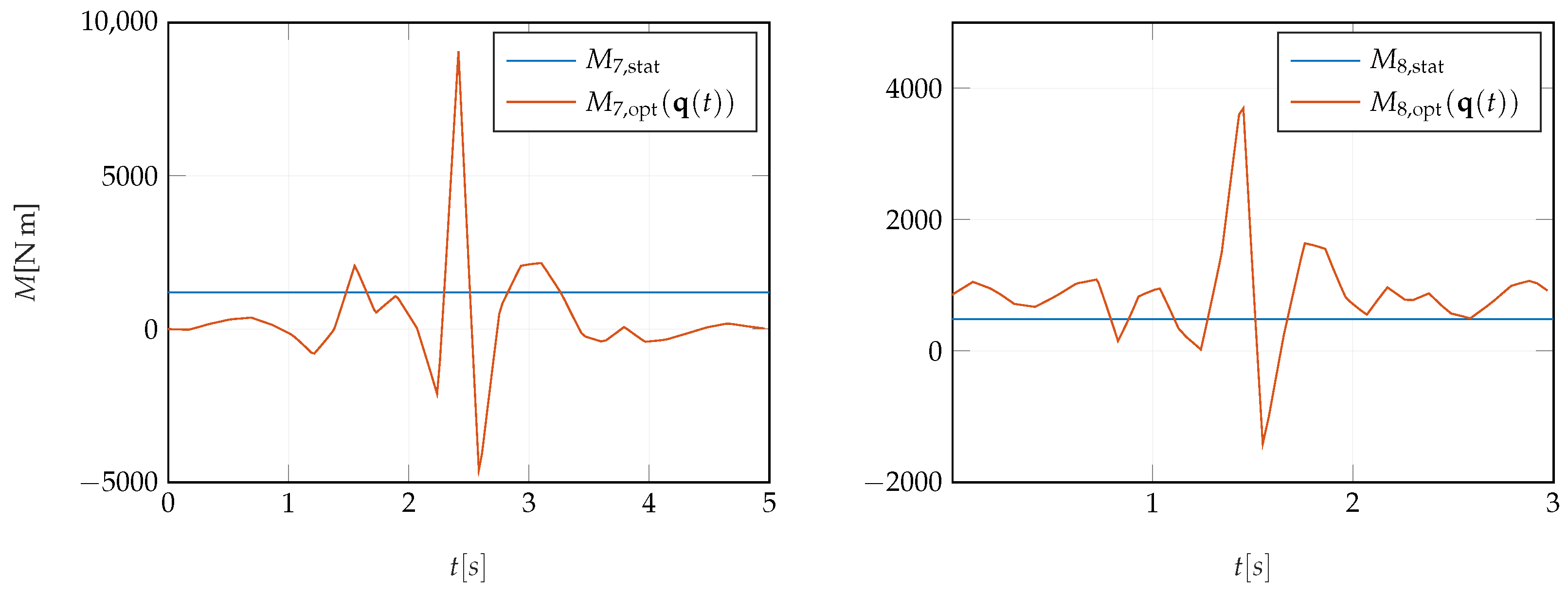
To show the difference between Equation (
1) and the optimization problem (
2) the result of both methods for calculating the maximum torque in the 7th and 8th axis is presented in
Figure 2. It depicts the calculated torque
M over time
t. The blue line shows torque
and
, which result from Equation (
1) and the orange line represents torque
and
, which result from solving the optimization problem (
2). For both methods, an angular acceleration of
was used for axis 7 and an angular acceleration of
for axis 8. Angular velocity limits for axis 7 and axis 8 were set to
and
, respectively. The position, velocity and acceleration limits for the actuators of the Stewart platform were set to the values specified in its documentation.
The sequential quadratic programming (SQP) algorithm, provided by the DLR Optimization Library, was used to solve the optimization problem (
2). The number of control points for each input was set to
and the simulation time was set to
s for axis 7 and to
s for axis 8. A simulation time of 5 s and 3 s, respectively, was found to be sufficiently long because the velocity and acceleration limits of the actuators were fully utilized. The full utilization of the limits is also the reason why it is assumed that the resulting trajectory represents a global optimum.
As can be seen in
Figure 2, the torques
and
are significantly higher than
and
, thus it can be concluded that it is important to take into account the movements of the structure or machine on which a motor is mounted when sizing the motor.
It was also possible to specify a moment in a certain axis or a force along a certain axis at a specified point in the multibody simulation model as the objective function to be maximized in the optimization problem (2). This approach provided load cases that could be used as external moments and forces in a stress analysis. In addition, the translational acceleration and angular acceleration could be determined by the multibody model, which were required for a stress analysis in a finite element software. The problem with this approach is that only one moment or one force could be maximized at a time. Suppose multiple moments and forces are defined as the objective function to be maximized. In that case, the different moments and forces are not maximized simultaneously, but each is maximized individually at any time between and . This method was used for the motion platform to determine four load cases, which were used to size the structure mounted on top of the Stewart platform.
The motion platform is currently being built. Once completed, measurement campaigns to validate the simulation results are planned. Additionally, a planning algorithm to optimally perform Cartesian movements exploiting the redundant platform design is in development.
Author Contributions
Conceptualization, T.B. (Thomas Bernhofer), A.S., T.B. (Tobias Bellmann) and P.W.; methodology, T.B. (Thomas Bernhofer) and A.S.; software, T.B. (Thomas Bernhofer); validation, T.B. (Thomas Bernhofer); formal analysis, T.B. (Thomas Bernhofer); investigation, T.B. (Thomas Bernhofer) and P.W.; resources, T.B. (Thomas Bernhofer); data curation, T.B. (Thomas Bernhofer); writing—original draft preparation, T.B. (Thomas Bernhofer) and P.W.; writing—review and editing, T.B. (Thomas Bernhofer) and A.S.; visualization, T.B. (Thomas Bernhofer); supervision, A.S. and T.B. (Tobias Bellmann). All authors have read and agreed to the published version of the manuscript.
Funding
This research received no external funding.
Informed Consent Statement
Not applicable.
Data Availability Statement
Not applicable.
Conflicts of Interest
The authors declare no conflict of interest.
References
- Stewart, D. A Platform with Six Degrees of Freedom. Aircr. Eng. 1966, 4, 30–35. [Google Scholar] [CrossRef]
- Bellmann, T.; Heindl, J.; Hellerer, M.; Kuchar, R.; Sharma, K.; Hirzinger, G. The DLR Robot Motion Simulator Part I: Design and setup. In Proceedings of the 2011 IEEE International Conference on Robotics and Automation, Shanghai, China, 9–13 May 2011. [Google Scholar]
- Jameson, A.H.; Horrobin, A.; Auckland, R.A. Whatever Happened to the LADS? Design and development of the new University of Leeds. In Proceedings of the Driving Simulation Conference North America 2007, Iowa City, IA, USA, 12–14 September 2007. [Google Scholar]
- Pitz, J.; Nguyen, M.; Baumann, G.; Reuss, H. Combined Motion of a Hexapod with a XY-Table System for Lateral Movements. In Proceedings of the Driving Simulation Conference 2014, Paris, France, 4–5 September 2014. [Google Scholar]
- Wilkinson, M.E.; Brown, T.L.; Ahmad, O. The National Advanced Driving Simulator (NADS) Description and Capabilities in Vision-Related Research. Am. J. Optom. 2012, 6, 79–84. [Google Scholar]
- Bernhofer, T. Design and Path Planning of an 8-Axis Parallel-Serial Motion Platform. Master’s Thesis, Technical University of Munich, Munich, Germany, 31 August 2021. [Google Scholar]
- Elmqvist, H.; Mattsson, S.E.; Otter, M. Modelica-the new object-oriented modeling language. In Proceedings of the 12th European Simulation Multiconference, Manchester, UK, 16–19 June 1998. [Google Scholar]
- Pfeiffer, A. Optimization Library for Interactive Multi-Criteria Optimization Tasks. In Proceedings of the 9th International Modelica Conference, Munich, Germany, 3–5 September 2012. [Google Scholar]
| Publisher’s Note: MDPI stays neutral with regard to jurisdictional claims in published maps and institutional affiliations. |
© 2022 by the authors. Licensee MDPI, Basel, Switzerland. This article is an open access article distributed under the terms and conditions of the Creative Commons Attribution (CC BY) license (https://creativecommons.org/licenses/by/4.0/).


 ) and the optimization problem (2) (
  ). The solution of the optimization problem (2) represents the maximum torque, which occurs at the worst case movement of the motion platform.