Abstract
Direct-contact condensation (DCC) has acquired an important role in the industrial sector due to its high mass and heat transfer rates. In this paper, the influence of steam pressure and water temperature on cavity shapes were studied from symmetrical and diagonal plane views. The cavity shapes observed were oscillatory, conical, ellipsoidal, and double expansion–contraction. The recompression shock wave at nozzle corners was found to cause steam cavity compression in the diagonal plane. The dimensionless penetration length was found to increase with the rise in steam pressure and water temperature and lay in the range from 3.38 to 5.55. The experimental data of dimensionless penetration length was in good agreement with previous correlations.
1. Introduction
Steam water direct-contact condensation (DCC) is a thermal hydraulic phenomenon that occurs when saturated/superheated steam is injected into subcooled water. Kerney et al. [1] conducted a pioneering study on DCC and presented a correlation for cavity penetration length. Kim et al. [2] presented empirical correlations for cavity penetration length and the average heat transfer coefficient for sonic nozzles.
Wu et al. [3] conducted an extensive study for supersonic nozzles and showed that cavity shapes were dependent upon shock and expansion waves at the nozzle exit. Quddus et al. [4] discussed the effect of the nozzle angle on DCC using a bevelled steam nozzle. Xu et al. [5] measured the heat transfer coefficient and penetration length using numerical investigation. Tsutsumi et al. [6] studied a square nozzle from both an experimental and Computational Fluid Dynamics (CFD) approach and obtained the shock structures on a diagonal and symmetrical plane.
In this current study, a supersonic square nozzle was used for steam injection due to its enhanced mixing and entrainment [7]. The influence of steam pressure and water temperature on cavity shapes and cavity penetration length were studied using image capturing and processing. The results of the current experimental study will help in the better designing of DCC-based industrial components with safer operation.
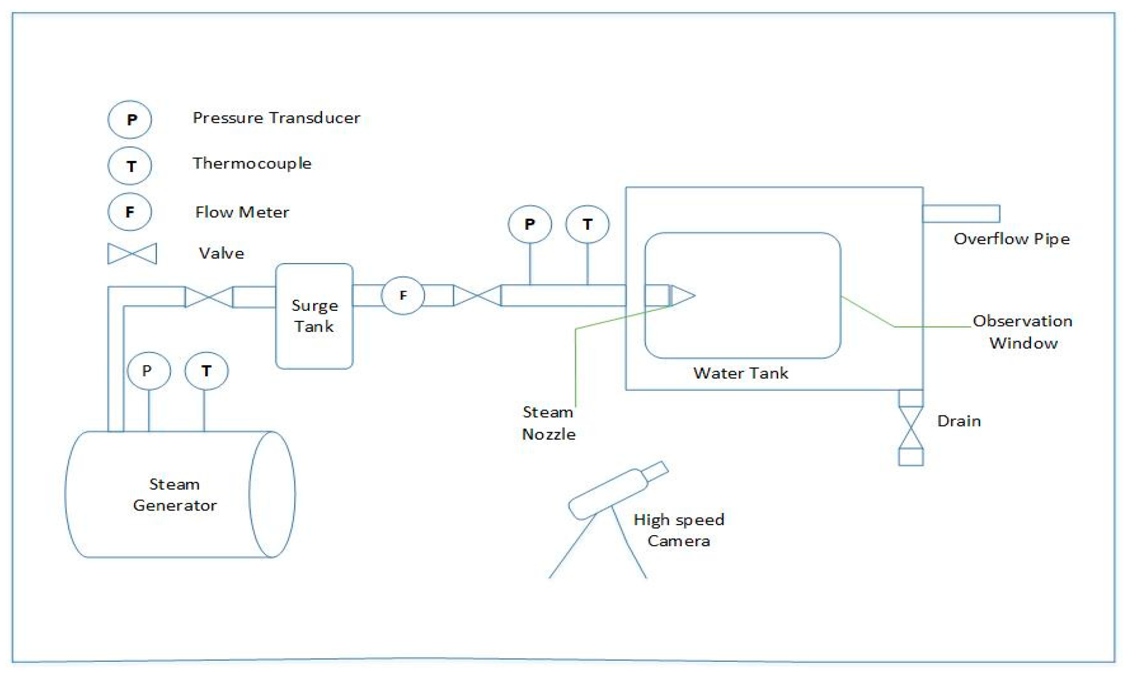
2. Materials and Methods
The experimental setup, shown in Figure 1, was designed to provide saturated steam injection in subcooled water. The electric boiler could provide 52 kg/h of steam (~99% quality), at a maximum pressure of 8 bar. The electric boiler was a cylindrical tank containing four electric heaters (9 kW capacity of one heater) submerged in water. Steam cavity was captured using a high-speed camera and processed using a MATLAB code. The operating conditions and nozzle dimensions are given in Table 1.
Figure 1.
Experimental Setup for DCC.
Table 1.
Operating conditions and nozzle dimensions.
3. Results and Discussion
In this section, the influence of steam pressure and water temperature on the cavity shapes and penetration length is discussed. A steam cavity was observed from the symmetrical plane and diagonal plane view [6]. Buoyancy effects were negligible at TW = 35 °C and 55 °C.
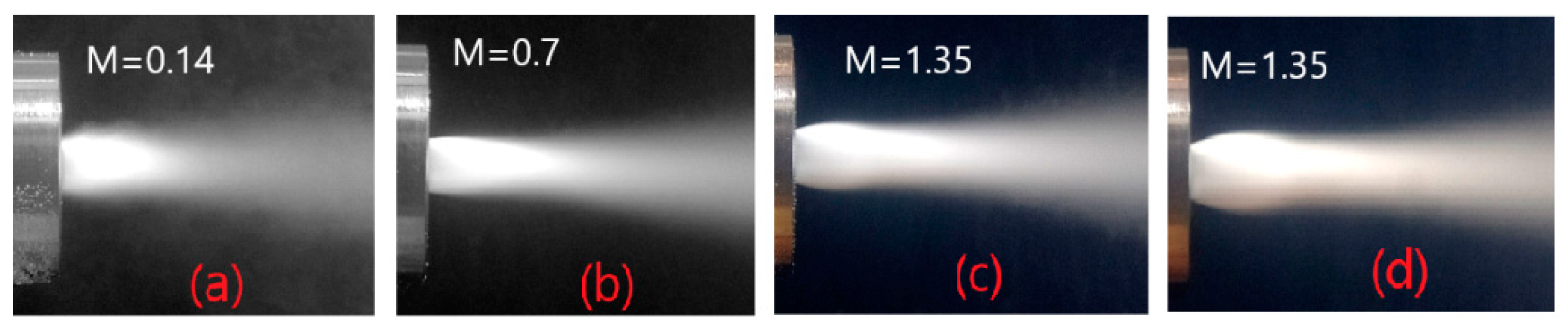
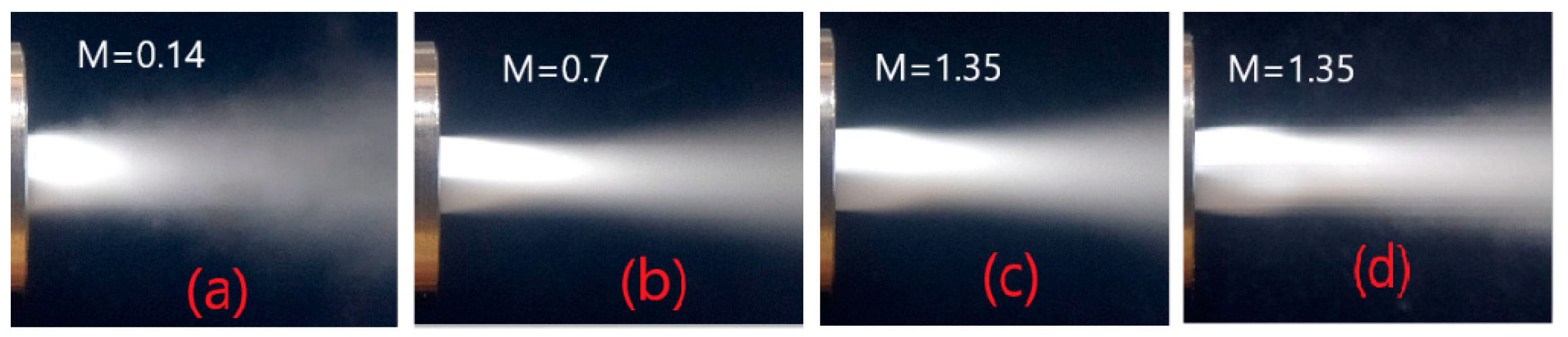
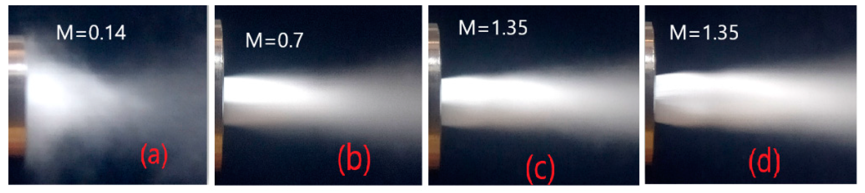
3.1. Influence of Steam Pressure and Water Temprature on the Cavity Shapes
As shown in Figure 2, the symmetrical plane view was captured at TW = 35 °C. At 1.5 bar, as shown in Figure 2a, oscillatory condensation occurred. At 2.5 bar, as shown in Figure 2b, a conical shape was observed, due to high degree of subcooling of water. At 3.5 bar, as shown in Figure 2c, an ellipsoidal shape was observed. The nozzle exit pressure was higher than ambient water pressure, so an expansion wave formed at the edges of the nozzle and steam expanded. Expansion waves interacted with the cavity boundary to make an intercepting shock wave and steam contracted. At 4.5 bar, as shown in Figure 2d, an ellipsoidal shape was observed with high expansion due to the stronger expansion waves.
Figure 2.
Symmetrical plane view. Steam pressure (bar) effect at TW = 35 °C (a) 1.5 (b) 2.5 (c) 3.5 (d) 4.5.
As shown in Figure 3, a diagonal plane view was captured at TW = 35 °C. At the nozzle corners, recompression shock waves formed due to the interaction of the expansion waves of the two adjacent edges, which formed an overexpanded region [6]. At 2.5 bar, as shown in Figure 3b, the cavity was conical due to recompression shock waves. At 3.5 bar, as shown in Figure 3c, the cavity was conical, but the cavity from the symmetrical plane view was ellipsoidal. This was due to recompression shock waves at the nozzle corners. In the diagonal plane, an intercepting shock wave also formed after the interaction of expansion waves with cavity boundary. The recompression shock wave at the nozzle corner as well as the intercepting shock wave contracted the steam. At 4.5 bar, as shown in Figure 3d, the cavity shape observed was ellipsoidal, but it was actually conical. At high steam pressure, expansion waves are stronger, resulting in stronger recompression shock waves at the corners. The expansion from the edges coming in front of diagonal plane is shown in Figure 3d. At 3.5 bar, as shown in Figure 3c, the expansion was small and did not appear in the diagonal plane view.
Figure 3.
Diagonal plane view. Steam pressure (bar) effect at TW = 35 °C (a) 1.5 (b) 2.5 (c) 3.5 (d) 4.5.
As shown in Figure 4, the symmetry plane view was captured at TW = 55 °C. At 1.5 bar, as shown in Figure 4a, condensation oscillation was found to be more violent due to the lower condensation potential at a higher water temperature. At 2.5 bar, as shown in Figure 4b, the cavity was ellipsoidal. This is due to the decrease in condensation potential, which increases the interface surface area for dissipating the heat coming from the steam. The increase in interface surface area was achieved by increasing the expansion and penetration length. At 3.5 bar, as shown in Figure 4c, the cavity is found to be a double expansion–contraction due to the addition of momentum and heat at high steam pressure. The cavity first expanded to cater for the extra heat and then it was compressed by the ambient water pressure. It then expanded again, as the pressure recovery was higher at high water temperature. At 4.5 bar, as shown in Figure 4d, the cavity shape was again double expansion–contraction, but with a higher expansion to cater for the addition of more heat.
Figure 4.
Symmetry plane view. Steam pressure (bar) effect at TW = 55 °C (a) 1.5 (b) 2.5 (c) 3.5 (d) 4.5.
As shown in Figure 5, the diagonal plane view was captured at TW = 55 ° C. At 2.5 bar, as shown in Figure 5b, the cavity was conical but ellipsoidal from the symmetry plane view, due to the recompression shock wave at the corners. At 3.5 bar and 4.5 bar, as shown in Figure 5c and Figure 5d, expansion from the edges came in front of the diagonal plane.
Figure 5.
Diagonal plane view. Steam pressure (bar) effect at TW = 55 °C (a) 1.5 (b) 2.5 (c) 3.5 (d) 4.5.
3.2. Influence of Steam Pressure and Water Temperature on the Penetration Length
The variation in the dimensionless penetration length is shown in a black line in Figure 6. The dimensionless penetration length was obtained by dividing it by the width of nozzle. As the steam pressure increased, the penetration length increased due to the increase in momentum transfer. At low temperatures, the penetration length was small due to the high condensation potential. At high temperatures, the interface area increased, which lead to a large degree of penetration. The dimensionless penetration length was found to be in the range of 3.38–5.55. The data lies in the range from −8.87% to +20.3% range with absolute deviation of 13.1%, when compared with correlation of Kerney and Kim.
Figure 6.
Variation of current data with predicted data (a) TW = 35 °C (b) TW = 55 °C.
4. Conclusions
Four cavity shapes were observed—oscillatory, conical, ellipsoidal, and double expansion–contraction. The steam cavity from the diagonal plane view was conical for all operating conditions due to recompression wave at the corner of the nozzle exit. The expansion captured in the diagonal plane view was that of the expansion from the nozzle edges at higher steam pressures. The penetration length increased with the rise in steam pressure and water temperature.
Author Contributions
N.A.K.: Conceptualization, Data curation, Methodology, Investigation, Formal analysis, Writing—original draft. A.S.: Investigation, Funding acquisition, Supervision, Conceptualization. A.Q.: Conceptualization, Project administration, Supervision. H.A.: Data curation. S.H.: Funding acquisition, Resources, Review. M.K.A.: Data curation, Writing and Review Editing. M.I.: Resources. All authors have read and agreed to the published version of the manuscript.
Funding
This research received no external funding.
Conflicts of Interest
The authors declare no conflict of interest.
References
- Kerney, P.; Faeth, G.; Oslon, D. Penetration characteristics of a submerged steam jet. AIChE J. 1972, 18, 548–553. [Google Scholar] [CrossRef]
- Kim, H.Y.; Bae, Y.Y.; Song, C.H.; Park, J.K.; Choi, S.M. Experimental study on stable steam condensation in a quenching tank. Int. J. Energy Res. 2001, 25, 239–252. [Google Scholar] [CrossRef]
- Wu, X.Z.; Yan, J.J.; Shao, S.F.; Cao, Y.; Liu, J.P. Experimental study on the condensation of supersonic steam jet submerged in quiescent subcooled water: Steam plume shape and heat transfer. Int. J. Multiph. Flow 2007, 33, 1296–1307. [Google Scholar] [CrossRef]
- Quddus, A.; Shah, A.; Qureshi, K.R.; Ayub, M.K.; Tahir, A.; Iqbal, M. Study of steam jet characteristics and regime maps for bevelled spray nozzles exhausting into quiescent water. Int. J. Heat Mass Transf. 2022, 190, 122780. [Google Scholar] [CrossRef]
- Xu, Q.; Liang, L.; She, Y.; Xie, X.; Guo, L. Numerical investigation on thermal hydraulic characteristics of steam jet condensation in subcooled water flow in pipes. Int. J. Heat Mass Transf. 2022, 184, 122277. [Google Scholar] [CrossRef]
- Tsutsumi, S.; Teramoto, S.; Yamaguchi, K.; Nagashima, T. Structure of underexpanded jets from square nozzles. AIAA J. 2006, 44, 1287–1291. [Google Scholar] [CrossRef]
- Zhang, H.; Chen, Z.; Jiang, X.; Guo, Z. The initial flow characteristics of supersonic jets with different geometries. Phys. Lett. A 2015, 379, 1256–1262. [Google Scholar] [CrossRef]
Publisher’s Note: MDPI stays neutral with regard to jurisdictional claims in published maps and institutional affiliations. |
© 2022 by the authors. Licensee MDPI, Basel, Switzerland. This article is an open access article distributed under the terms and conditions of the Creative Commons Attribution (CC BY) license (https://creativecommons.org/licenses/by/4.0/).