Proceeding Paper

Development of a Computational Tool for Maneuver Loads Estimation in Initial Design Phase for Fighter Aircraft †

by
Chaudry Rohan Rafiq
* and
Waqar Ahmed Qureshi
Department of Mechanical Engineering, University of Engineering and Technology Taxila, Punjab 47050, Pakistan
*
Author to whom correspondence should be addressed.
Presented at the 2nd International Conference on Advances in Mechanical Engineering (ICAME-22), Islamabad, Pakistan, 25 August 2022.
Eng. Proc. 2022, 23(1), 2; https://doi.org/10.3390/engproc2022023002
Published: 20 September 2022
(This article belongs to the Proceedings of The 2nd International Conference on Advances in Mechanical Engineering)

Abstract

:
The determination of aircraft loads in the preliminary design phase is important for the optimal design of aircraft structures. In this paper, the inflight load calculation methodology for aircraft in the preliminary design phase is formulated in the form of a computer tool developed in MATLAB/Simulink environment. In this tool (Loads Model), aircraft maneuvers are simulated, and the corresponding time histories of loads (shear force, bending moment) on the aircraft components (wing, horizontal tail, vertical tail, fuselage) are obtained, which are required for the preliminary structural design of the aircraft. The loads tool can be used to implement the design loads requirements established in “NATO RTO-45” for control configured fighter aircraft.

1. Introduction

The structural design cannot be initiated unless the loads acting on the aircraft are accurately determined. The procedures for design loads calculation for different aircraft types are readily available in the literature [1,2]. Modern military fighter aircraft are controlled by a fly-by-wire system and carefree handling technology. Hence, the determination of loads for aircraft with carefree handling capability and a load-limiting flight control system is different from conventional methods. For the design loads determination of military fighter aircraft, the NATO RTO-45 [3] specifications have been followed, which requires a loads tool to be developed for maneuver loads estimation.
A loads model (loads tool) is a platform in which the critical inflight load cases are simulated, and the loads of aircraft for different components are determined. In this paper, a loads model is developed in the Simulink environment of MATLAB. The loads model and the guidelines defined in [3] are used to determine the flight loads acting on the aircraft that are subsequently required for the preliminary design of the aircraft structure.

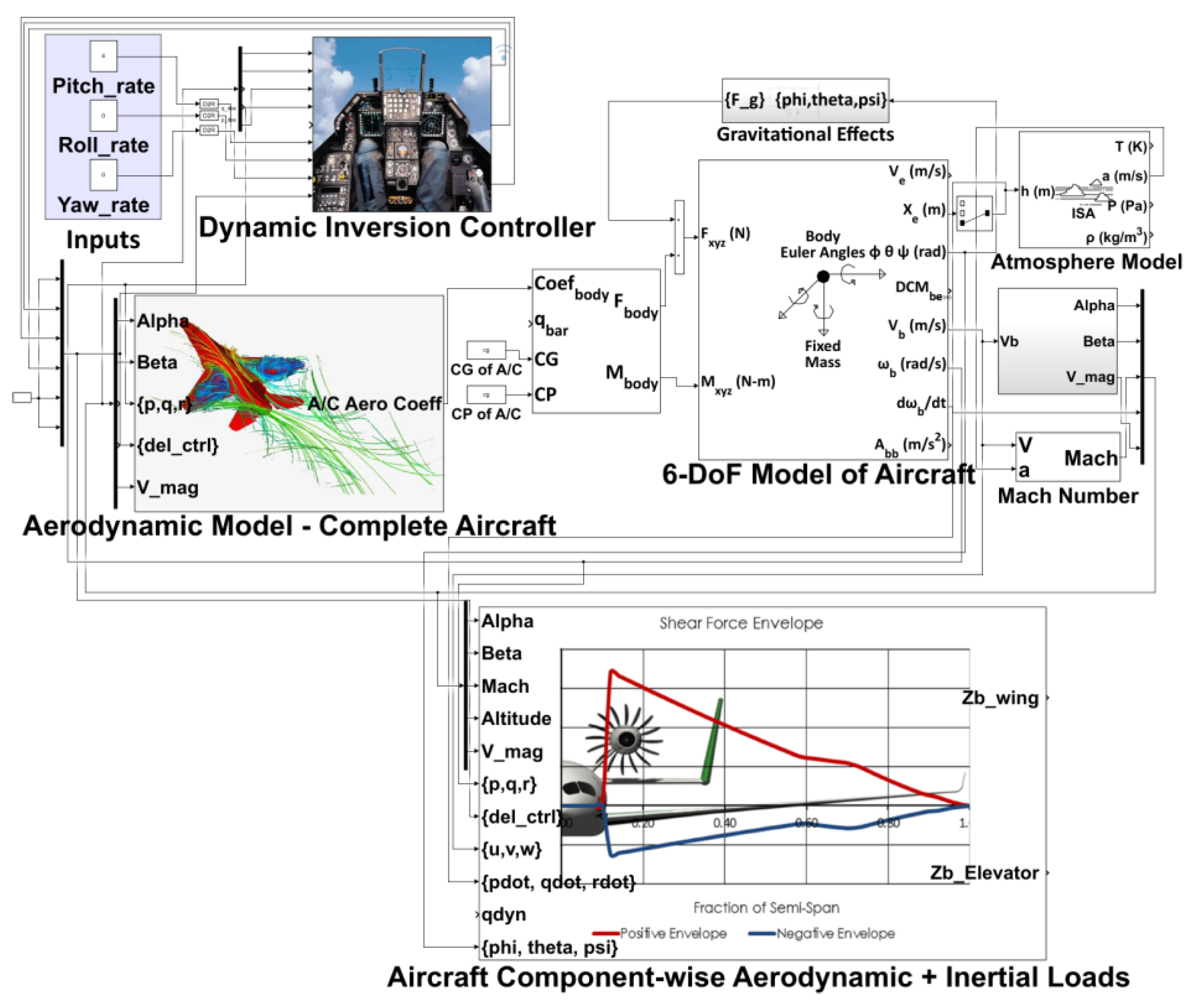
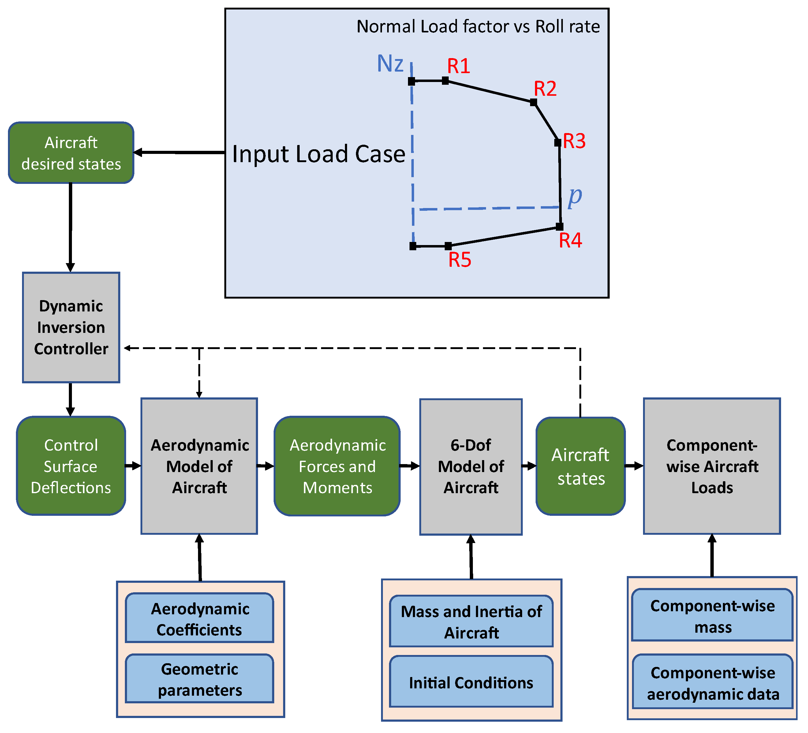
2. Framework of Inflight Loads Calculation Tool

In the loads model, the flight dynamics block is linked with a feedback controller to perform the maneuvers specified in different military aircraft design standards for loads estimation. The flow of the whole loads model has been defined to present a clear picture of the load’s framework that is being used for aircraft loads estimation.
The flight dynamics model (FDM) provides the aircraft states (roll rate(p), pitch rate(q), yaw rate(r), angle of attack(α), sideslip(β), load factor (Nz)) time histories as a result of control inputs. The outputs of the flight dynamics model are used as inputs for the loads computation block, which calculates the loads acting on various aircraft components. The Loads Model developed in Simulink is shown in Figure 1. The framework of the Loads Model is shown in Figure 2.
[ u ˙ v ˙ w ˙ ] = 1 M [ X Y Z ] + g [ s i n θ s i n Φ c o s θ c o s Φ c o s θ ] + [ r v q w p w r u q u p v ]
[ p ˙ q ˙ r ˙ ] = [ I x x 0 I x z 0 I y y 0 I z x 0 I z z ] 1 + [ L + ( I y y I z z ) q r + I x z ( p q ) M + ( I z z I x x ) p r + I x z ( r 2 p 2 ) N + ( I x x I y y ) p q I x z q r ]
[ Φ ˙ θ ˙ ψ ˙ ] = [ 1 s i n Φ s i n θ c o s θ c o s Φ s i n θ c o s θ 0 c o s Φ s i n Φ 0 s i n Φ c o s θ c o s Φ c o s θ ] [ p q r ]
where u, v, and w are the velocities and X, Y, Z, L, M, and N are the moments about the body axes of aircraft, where Φ ,   θ ,   and   ψ are the bank, elevation, and directional angle of the aircraft.
A Dynamic Inversion (DI) Controller is implemented in the Simulink Loads Model to generate the required control surfaces deflections (δe (elevator deflection), δa (aileron deflection), δr (rudder deflection)) to make the aircraft follow desired rates (p, q, r). The NDI controller has been modeled in Simulink using the guidelines outlined in [4,5].

Aircraft Loads (Component-Wise)

The maneuver state variable time-histories of the aircraft are used in conjunction with the component-wise aerodynamic coefficients for the calculation of component lift, drag, side force, and twisting moments. The loads equations for all the components of the aircraft are formulated using the approaches described in [1,6,7,8].
The equations for the lift of the wing and horizontal tail are given in Equations (4) and (5). The equation of drag is given in Equation (6), where CL and CD are the lift and drag coefficients, respectively.
L e ( t ) = q S w   [ C L e ( α e ( t ) ,   β e ( t ) ,   M ,   h ) + C L δ e e ( α e ( t ) ,   β e ( t ) ,   M ,   h )   δ e
L w ( t ) = q S w   [ C L w ( α w ( t ) ,   β ( t ) ,   M ,   h ) + C L q ^ w ( α w ( t ) ,   β ( t ) ,   M ,   h )     q ^ ( t ) )     c ¯ w 2 V + C L δ a w ( α w ( t ) ,   β ( t ) ,   M ,   h )   δ a
D e , w ( t ) = q S w [ C D e , w ( α e , w ( t ) ,   β e , w ( t ) ,   M ,   h ) ]  
where q and Sw are the dynamic pressure and wing reference area of the aircraft. The superscript represents the coefficient of the respective component. Additionally, the change in the angle of attack due to aircraft rotational rates has also been incorporated. The equation of the wing angle of attack is shown in Equation (7).
α w ( t ) = α ( t ) + tan 1   ( p ( t ) y c p w u r ( t ) y c p w )
The equations for the vertical tail are also formulated using the same approach and assumptions. Finally, the aerodynamic and inertial loads are added, and resultant shear force and bending moments at the root of the respective component are obtained.

3. Results and Validation of Loads Model

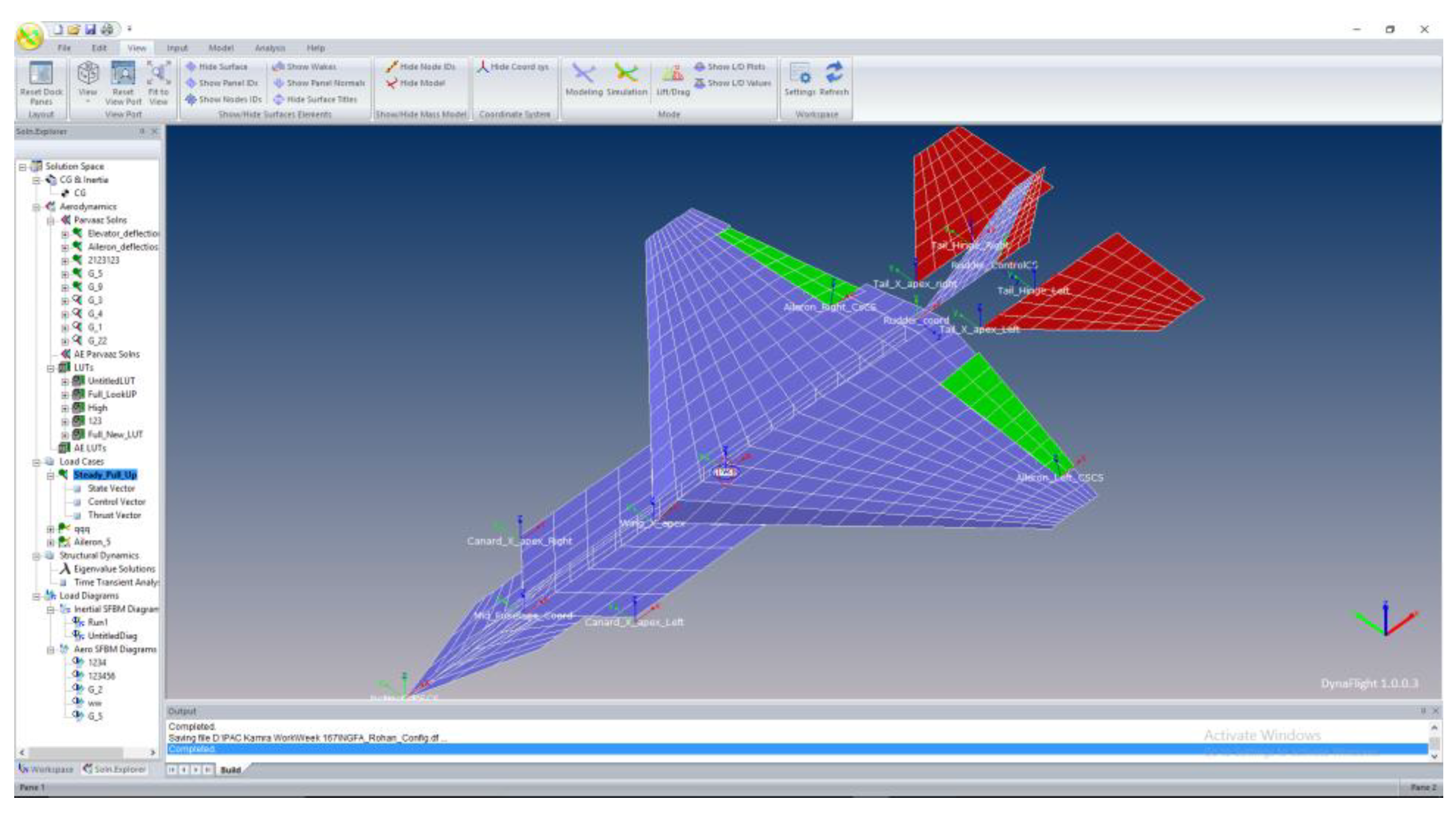
3.1. Validation with DynaFlight Results

For the validation of the tool developed in this research, the trim analysis of the Loads Model developed in Simulink for a sample aircraft is compared with the results of existing aircraft loads calculation software, “DynaFlight”.
The sample aircraft for which trim analysis has been performed is shown in Figure 3. The aerodynamic model of the sample aircraft and user interface of Dynaflight is shown in Figure 4. The mass of the aircraft is 18,500 kg.
The comparison of the trim analysis for both the software for 5G pull-up and 1G level flight conditions at 0.8 Mach (M) at sea level is shown in Table 1 and Table 2.
For simplicity and fast computation of results, panel methods are used to obtain the aerodynamic data of the aircraft. The effects of unsteady or transient aerodynamics on wing lift due to unsteady pitching maneuvers are ignored. The aerodynamic data are obtained at discrete points, and the linear interpolation is used by the built-in Lookup tables of Simulink. For simplicity, the center of pressure (CP) is kept at 0.25 of the mean aerodynamic chord (MAC) of the lifting surface.
In longitudinal trim conditions, the load is also carried by the fuselage. The load on the fuselage is not shown in the table above. The error in the wing load for the 1G condition is larger due to the way the aerodynamic data of the individual component is stored in the Simulink model. To reduce the error, the aerodynamic data of the individual components should be obtained by taking into consideration the effects of lifting surfaces present in front of the wing. The angle of attack is a flight parameter, and the difference in the value of the angle of attack (α) could be the result of different numerical solution techniques used for the solution of flight dynamics equations in both software.

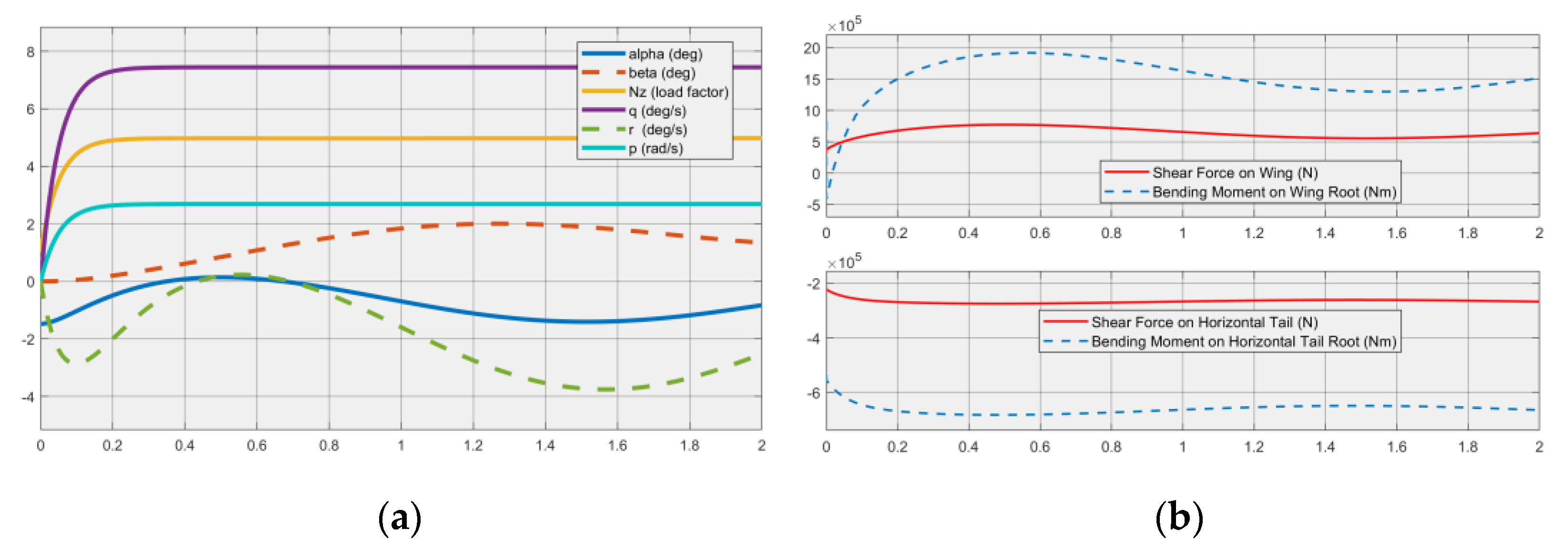
3.2. A Sample Load Case According to Flight Parameter Envelopes Approach (FPEA)

A run case for determining the maneuver loads of the sample aircraft according to the guidelines of the FPEA described in [3] is shown in this section.
The combination of the normal load factor and the roll rate serves as a critical case for the rolling maneuvers. Hence, the loads for the normal load factor coupled with the roll rate have been simulated in the loads model of Simulink, and the results are shown.
The case on the flight parameter envelope as R2 in Figure 2 has been simulated in the Simulink Loads model, and the corresponding shear force and bending moment on the wing are displayed. At R2, the Nz is “5”, and the roll rate (p) is taken as “150 deg/s”.
The wing and tail loads of the sample aircraft have been found using the simulation of 2 s in Figure 5. The simulation shows the time histories of aircraft flight parameters and component loading. The time history of the value of Load Factor (Nz) along with the roll rate (p) shows that the NDI controller works fine for the tracking of desired parameters, and the components' shear force and bending moments can be determined.

4. Conclusions and Future Recommendations

The loads tool has been developed, validated, and further used to determine the loads on different components of the aircraft. Additionally, a critical load case according to the Flight Parameter Envelopes Approach (FPEA) has been simulated, and the loads on the aircraft wing and horizontal tail are determined. All the other flight parameter envelopes of the aircraft given in [3] need to be simulated for all the possible Mach numbers, altitudes, and mass states for complete loads analysis. The capability of outputting the loads time histories and having a controller for maneuver simulation makes this tool much more feasible for maneuver loads determination compared to “Dynaflight”.
The flexibility effects of the aircraft structure need to be incorporated into the current loads tool. Additionally, an aerodynamic tool for the determination of aerodynamic forces and moments in the simulation run time needs to be included in the current loads determination tool to make this tool a complete standalone loads software.

Author Contributions

Conceptualization, C.R.R. and W.A.Q.; methodology, C.R.R.; software, C.R.R.; validation, C.R.R.; writing—original draft preparation, C.R.R.; writing—review and editing, W.A.Q. All authors have read and agreed to the published version of the manuscript.

Funding

This research received no external funding.

Institutional Review Board Statement

Not applicable.

Informed Consent Statement

Not applicable.

Data Availability Statement

Not applicable.

Conflicts of Interest

The authors declare no conflict of interest.

References

  1. Howe, D. Aircraft Loading and Structural Layout; Professional Engineering Publishing: London, UK, 2004. [Google Scholar]
  2. Krüger, W.; Klimmek, T. Definition of a Comprehensive Loads Process in the DLR Project ILOADS. In Proceedings of the Deutscher Luft- und Raumfahrtkongress 2016, Braunschweig, Germany, 13–15 September 2016. [Google Scholar]
  3. Nato Research and Technology Organization Neuilly-Sur-Seine (France). Design Loads for Future Aircraft; 2002. Available online: https://www.sto.nato.int/publications/STO%20Technical%20Reports/RTO-TR-045/TR-045-$$ALL.pdf (accessed on 19 September 2022).
  4. Vadali, R.; Majji, M.; Huff, G. Nonlinear Adaptive Dynamic Inversion Control for Variable Stability Small Unmanned Aircraft Systems; Texas A&M University: College Station, TX, USA, 2017. [Google Scholar]
  5. Smith, S.C.; Swaroop, D.V.A.H.G.; Valasek, J.; O’neal, D. Aircraft Control Using Nonlinear Dynamic Inversion in Conjunction with Adaptive Robust Control; Texas A&M University: College Station, TX, USA, 2004. [Google Scholar]
  6. Lomax, T.L. Structural Loads Analysis for Commercial Transport Aircraft; AIAA: Reston, VA, USA, 1996. [Google Scholar]
  7. Niu, M.; Niu, M.C.Y. Airframe Stress Analysis & Sizing, 1st ed.; Hong Kong Conmilit Press Ltd.: Hongkong, 1997. [Google Scholar]
  8. Wright, J.R. Cooper Introduction to Aircraft Aeroelasticity and Loads; John Wiley & Sons: Hoboken, NJ, USA, 2008; Volume 20. [Google Scholar]
Figure 1. Loads tool developed in Simulink.
Engproc 23 00002 g001
Figure 2. Loads tool framework.
Engproc 23 00002 g002
Figure 3. Aircraft model.
Engproc 23 00002 g003
Figure 4. DynaFlight interface.
Engproc 23 00002 g004
Figure 5. (a) Angle of attack (α), sideslip (β), normal load factor (Nz), pitch rate(q), yaw rate (r), and roll rate (p) vs. time. (b) Shear force on wing and horizontal tail, bending moment on wing root and horizontal tail root vs. time.
Engproc 23 00002 g005
Table 1. Results for 5G pull-up maneuver.
ParameterSimulinkDynaFlightDifference
Angle of Attack (deg)1.41.612.5%
H-Tail Deflection (deg)−8.9−9.193%
Shear Force on Wing (N)651,892658,9931%
Shear Force on Horizontal Tail (N)−242,342−243,2110.4%
Table 2. Results for 1G level flight condition.
ParameterSimulinkDynaFlightDifference
Angle of Attack (deg)−1.36−1.477.4%
H-Tail Deflection (deg)−5.48−5.572%
Shear Force on Wing (N)363,436309,39514.8%
Shear Force on Horizontal Tail (N)−211,619−212,5090.5%
Publisher’s Note: MDPI stays neutral with regard to jurisdictional claims in published maps and institutional affiliations.

