Proceeding Paper

Development of CNC-Based Automated Soldering Machine †

by
Hafsa Wahid
1,*,
Hufsa Hashmi
2,
Muhammad Umer Baig
2,
Nawab Ahmed Raza
2,
Muhammad Faizan Sheikh
2 and
Muhammad Yousif Bhutto
2
1
Department of Electrical Engineering, NED University of Engineering and Technology, Karachi 75270, Pakistan
2
Department of Electrical Engineering, Sir Syed University of Engineering and Technology, Karachi 75300, Pakistan
*
Author to whom correspondence should be addressed.
Presented at the 7th International Electrical Engineering Conference, Karachi, Pakistan, 25–26 March 2022.
Eng. Proc. 2022, 20(1), 17; https://doi.org/10.3390/engproc2022020017
Published: 29 July 2022
(This article belongs to the Proceedings of The 7th International Electrical Engineering Conference)

Abstract

:
Researchers have proposed several designs and techniques to obtain sustainable development for industries for which growth will be escalated by automation in the future. Nowadays, automated soldering for printed circuit boards (PCBs) employs vision-based and artificial intelligence-based techniques which are complex and expensive. Computer numeric control (CNC), which has been used for machining, drilling, and milling purposes, is very popular as it proves to be highly accurate, flexible, and precise. In this regard, a low-cost and less complex automated soldering machine is proposed in which a temperature-controlled soldering station and CNC are integrated into a single machine to complete the soldering operation. This design will help minimize the complexity and cost of soldering stations for small-scale and medium-scale production industries.

1. Introduction

With the rampant use of machines in enterprises, mainly since the commercial revolution and technological innovation, humans’ manufacturing ability continues to increase. Machines can help automate production techniques, yielding more output in the same amount of time [1]. However, for sustainable development, the efficient usage of equipment is important. Researchers have proposed several designs and techniques to obtain sustainable development for industries employing manipulation and automation. Automation has diverted the workforce toward techniques that require the critical thinking abilities of a human. This engages people in more skilled labor and leaves the intensive and repetitive tasks to equipped machinery and robots [2]. For the introduction of automation strategies, small and medium-sized production batches have been targeted so one can produce cost-effective and flexible results, culminating with the development of CNC machines, flexible manufacturing systems (FMS), mobile robots such as automated guided vehicles (AGVs), and manipulator arms [1].
The automatic soldering machine is an automated device. Its operating precept is to use the robotic motion function to finish the soldering operation [3]. The market of automated soldering of printed circuit boards (PCBs) has been dominated by expensive and sophisticated technologies of computer vision-enabled and artificial intelligence-based robots. Several researchers have presented their work on vision-based robots in which vision-guided systems process the camera images and make decisions regarding the positioning of the soldering iron. While this method is more efficient than conventional soldering, its complicated computations have limitations of flexibility and increased costs for small-scale productions. Artificial intelligence (AI) technology has also been investigated in recent years where a deep-learning-based method has been used to detect an object to control a robotic arm. Such intensive algorithms can be replaced by a lighter framework such as OpenCV. In this domain, OpenCV models are also used to recognize the marker placed on the object. Since the electrical contacts on components are small in size, such marker-based recognition would not be appropriate for automated soldering applications [2].
To cater to the limitations of the above-mentioned technologies, a more flexible and highly controlled system is required. Nowadays, computer numeric control (CNC) is one of the popular technologies in the field of manufacturing. A CNC machine is a more flexible, precise, consistent, and highly accurate automatic machine [4,5]. CNC has been used for milling, drilling, and grinding [6], while no one has investigated the use of CNC for soldering. Therefore, a highly automated soldering machine is developed by integrating two machines; temperature-controlled soldering station and CNC into a single machine to complete the soldering operation. Automatic soldering is split into semi-computerized soldering gadgets and automated soldering devices. For robotic movement, Mach3 software is used which is viewed as the most reliable and user-friendly software package for CNC. The soldering arm extension consists of two sections, a temperature-controlled soldering iron and a solder feeder. Many variables can be set in the soldering station, such as temperature, length, and period. Arduino Nano is used for the interconnectivity of machines (soldering and CNC), for the proper wire feeding rate. The Arduino-based controller is easy to program and is very economical to use. Then, the automatic soldering gadget will constantly operate according to the set technique. This will enhance the productivity in minimum time duration and provide custom soldering to small-scale and medium-scale productions. Section 2 consists of all the materials and methodology required to achieve the desired objective while Section 3 represents the discussion and conclusion.

2. Materials and Methodology

The procedure involves the controlling of soldering variables such as soldering wire, feed charge, and temperature element from the semi-computerized soldering version and relative movement control between the soldering iron and its workpieces.

2.1. Soldering

Hakko 907 digital soldering station is cloned with modification in its heating element. The virtual iron is appropriate for soldering lead-unfastened solder at a set temperature of 350 °C because it converges quickly to the set temperature. The iron module was designed by considering ceramic warmers [7,8].

2.1.1. Measurement of Resistance at the Heating Element

  • Remove the nut tip, enclosure tip, and nipple.
  • Push the cord assembly in the direction of the tip and remove the terminal board from the handle.
  • Remove the grounding spring from the D-sleeve.
  • Measure the resistance values at the sensor and heating element of the terminal board in normal conditions.

2.1.2. Replacement of the Heating Element

  • De-solder the heating element leads, and sensor leads.
  • Remove the old heating element and replace it with a new one.
  • Solder the new heating element lead to the terminal board then cut the extra lead.

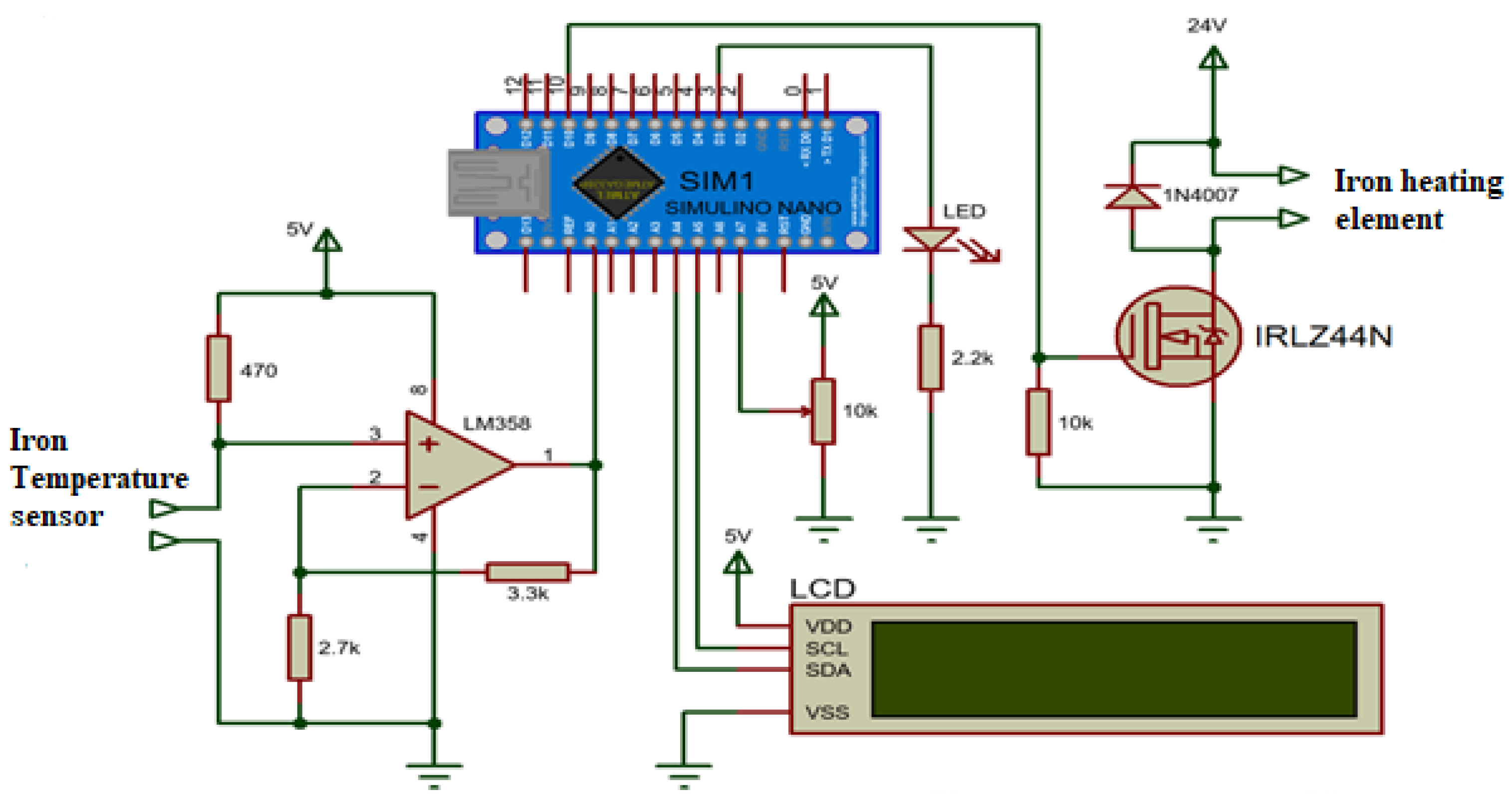
2.2. Digital Soldering Station

The automatic digital control machine of the soldering station constantly adjusts the dimmer knob through Arduino. When the machine detects that the temperature of the iron tip is lower than the set temperature, the device ramps up the energy required to generate heat in the iron tip. When the iron temperature is higher than the set temperature, power to the iron is reduced, causing a drop in temperature. The device performs this process fast, constantly turning the heating element of the iron on and off to preserve a regular temperature at the tip. Therefore, warm-up times are considerably quicker with virtual soldering stations [9,10]. Figure 1 shows the schematic diagram of the digital soldering station.

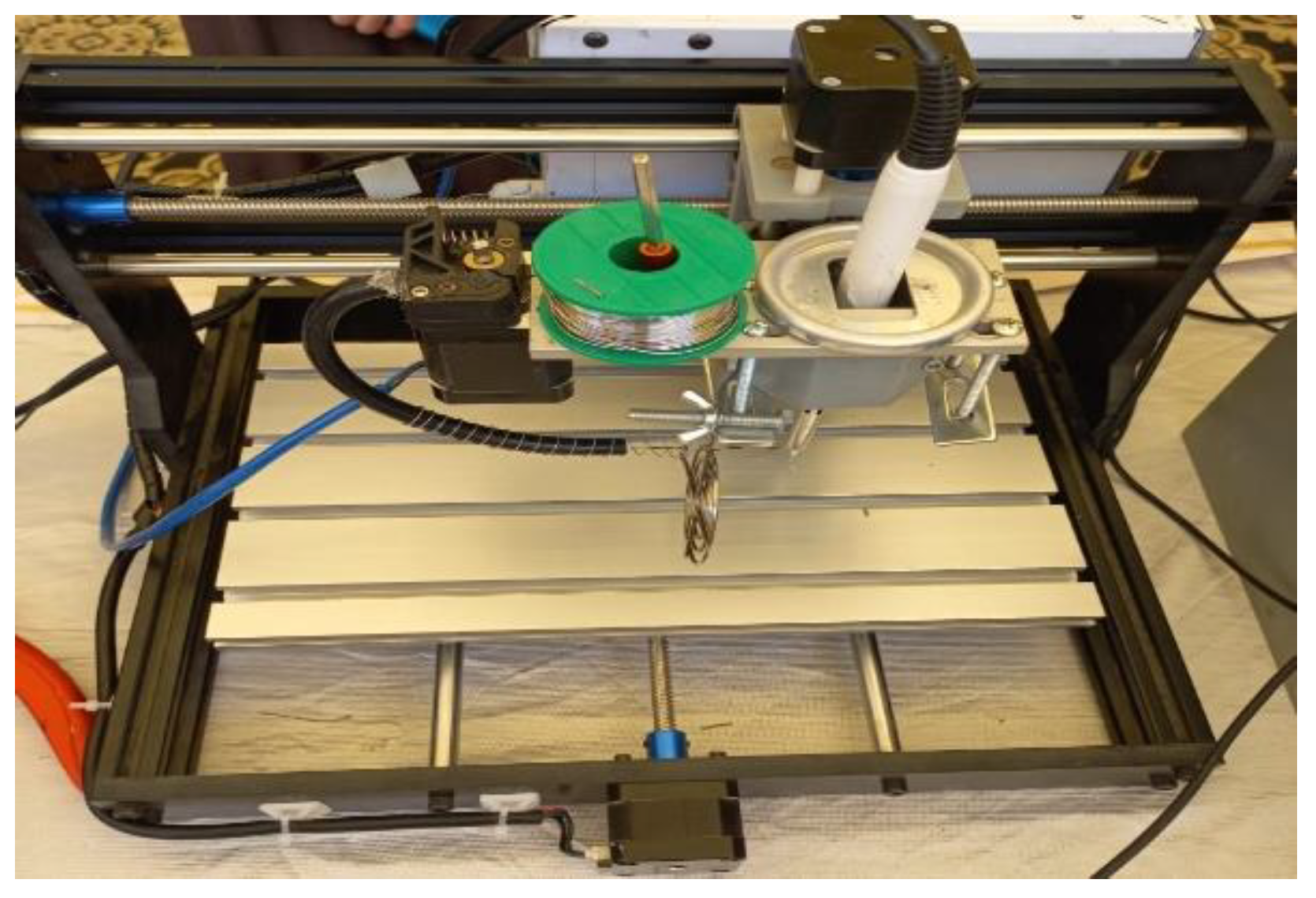
2.3. Manufacturing of CNC (Computer Numeric Control)

2.3.1. Electromechanical Components

Includes 3 stepper vehicles for movement alongside the x, y, and z axes, a PVC built frame, an excessive-velocity spindle motor, lead screws for power transmission, and other associated accessories. The linear slide and driving force are connected through an unmarried cable which decreased the area required for wiring and different installations processes. A vibration suppression feature to ensure easy operation was added. When the subsequent protective capabilities are activated, the motor stops mechanically, and the alarm rings [11].
Components used in the traveling of slide and motion control parts are following:
  • Five-phase stepper motor,
  • Flexible couplings,
  • Bearings,
  • Lead screw,
  • Limit switch.
Four stepper motor drivers are used to power the stepper vehicles for transferring the bits along the x, y, z, and a-axis instructions. The stepper drivers are powered with the aid of a switched-mode power supply (SMPS) DC energy source of 24 V Drive Technology. Stepper drivers are reconfigurable with extraordinary settings for maximum permissible jogging cutting-edge, stall cutting-edge, excitation modes of stepper motor actuation, and so on. Flexible couplings are used for linking the motor shaft to the ones of other gadgets. The linear motion slides generally use unique varieties of bearing consisting of linear roller bearings, simple bearings, dovetail bearings, ball bearings. Lead screws convert rotary motion to linear motion and are available in a variety of configurations. Screws are to be had with distinctive lengths, diameters, and thread pitches. Nuts range from the simple plastic variety to precision ground variations with re-circulating ball bearings that may reap very high accuracy [4,5].

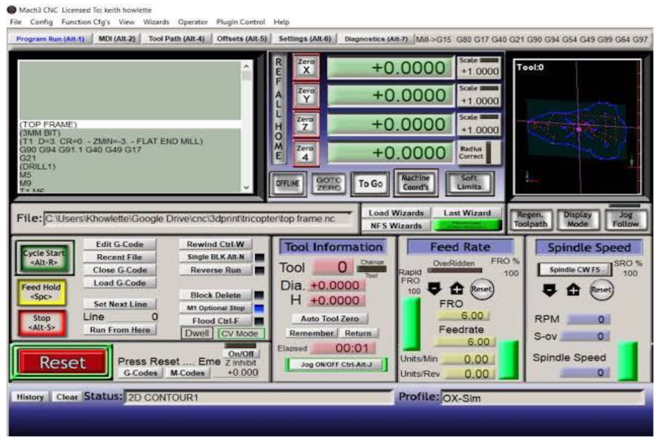
2.3.2. CNC Control Software

Mach3 interface card has been used for interfacing the steppers to computer Mach3 software version 3.043.066 to operate the CNC. Figure 2 shows the interface of Mach3 software. The card only allows operating stepper motors of rating up to 5 volts, 1.2 amps, so TB6600 stepper drives for each stepper motor are used. Mach3 is used to generate CNC machine G-code and M- code signals so one can power stepper motors using the Arduino Nano microcontroller. G-code and M-code are programming languages that can be interpreted by way of CNC controllers. G-code provides training instructions for function, velocity, and route of the motion, whereas M-code offers auxiliary instructions for spindle motor pace, coolant flow, tool change, and so on [11].

2.4. Techniques and Fabrication

The most important system additives are two 3-axis (XYZ) micromanipulators (Sutter Instruments MPC-285), a motorized XY level (Nikon Ti-S-ER), solder pen (HAKKO FX888D-23BY), and solder feeder unit (HAKKO-373). A customized controller is used to simultaneously manipulate up to 4 of the Sutter manipulators. One micromanipulator is being used to preserve and control the solder pen in conjunction with the solder feeder; the second micromanipulator is being used to preserve and control the wire to be soldered to the PCB [12]. Figure 3 represents the hardware model of a CNC-based automated soldering station.
The solder feed manages the usage of the self-feeder, which offers control over the time and speed of the feed. These controls can be set using physical knobs at the feeder, operating the feed through a push button at the feeder. This automates the feeding system and allows you to manage this from a computer, by a CD4066B chip (a quad bilateral switch IC) included with an Arduino Nano microcontroller [12].

3. Discussion and Conclusions

The automated soldering station increases the stability in the soldering process with fewer errors, tends to improve the quality of manufactured products, provides custom soldering for small-scale manufacturing, reduces human intervention, and minimizes the time of production. However, controlling the solder wire is difficult when it is mounted away from the soldering tip hence it is mounted alongside the iron to limit error rates in the soldering process resulting in the achievement of maximum soldering in the desired region.

Author Contributions

Conceptualization, H.W.; methodology and software, M.U.B.; investigation and data curation, N.A.R., M.F.S. and M.Y.B.; writing—original draft preparation, M.U.B. and N.A.R. and M.F.S.; writing—review and editing, H.W. and H.H. All authors have read and agreed to the published version of the manuscript.

Funding

This research received no external funding.

Data Availability Statement

Computer code used to control CNC is available on request to the author.

Acknowledgments

We thank two individuals Fahad and Zafar for their technical support.

Conflicts of Interest

The authors declare no conflict of interest.

References

  1. Santiago, S.B.; Almeida, E.L.O.; Dias, J.O. Automatic welding process: A study case of Soldering Machine. In Proceedings of the International Conference on Industrial Engineering and Operations Management, Toronto, ON, Canada, 23–25 October 2019. [Google Scholar]
  2. Thandapral, J.J.; Mugelan, R.K. Solderbot: Automated Soldering using Robot Arm. Int. J. Sci. Res. (IJSR) 2021, 10, 48–52. [Google Scholar]
  3. McKerrow, R. Optimization of Robotic Soldering Process: A Focus on Solder Spread and Spattering. In Proceedings of the SMTA International Conference, Virtual, 28 September–23 October 2020. [Google Scholar]
  4. Mamilla, V.R.; Srinivasulu, M.; Mani, P.N. Study on computer numerical control (CNC) machines. Int. J. Adv. Sci. Res. (IJASR) 2016, 1, 21–25. [Google Scholar]
  5. Misra, A.S.; Singh, G.; Kumar, A.; Rastogi, V. Design and Development of a Low-Cost CNC Alternative SCARA Robotic Arm. In Proceedings of the Third International Conference on Computing and Network Communications (CoCoNet’19), Trivandrum, India, 18–21 December 2019. [Google Scholar]
  6. Patel, N. Study on computer numerical control (CNC) technology. Int. Res. J. Eng. Technol. (IRJET) 2020, 7, 2883–2887. [Google Scholar]
  7. Cecil, J.V.D.; Powell, D. A review of gripping and manipulation techniques for micro-assembly applications. Int. J. Sci. Res. (IJSR) 2005, 43, 819–828. [Google Scholar] [CrossRef]
  8. Zhou, Y.; Nelson, B.J. The effect of material properties and gripping force on micro grasping. In Proceedings of the IEEE International Conference on Robotics and Automation (ICRA), San Francisco, CA, USA, 24–28 April 2000. [Google Scholar]
  9. Cappelleri, D.P.; Fink, J.; Gavrea, B.; Kumar, V. Automated assembly for meso-scale parts. IEEE Trans. Autom. Sci. Eng. 2011, 8, 598–613. [Google Scholar] [CrossRef]
  10. Das, A.M.R.; Popa, D.; Stephanou, H. A multiscale assembly and packaging system for manufacturing of complex micro-nano devices. IEEE Trans. Autom. Sci. Eng. 2011, 9, 160–170. [Google Scholar] [CrossRef]
  11. Smid, S. CNC Programming Handbook, 2nd ed.; Industrial Press: New York, NY, USA, 2002. [Google Scholar]
  12. Khandpur, R.S. Printed Circuit Board Design, Fabrication Assembly and Testing; Tata Publisher McgrawHill Education: Delhi, India, 2005. [Google Scholar]
Figure 1. Schematic diagram of digital soldering station.
Engproc 20 00017 g001
Figure 2. The interface of Mach3 CNC control software.
Engproc 20 00017 g002
Figure 3. Hardware design of CNC-based soldering station.
Engproc 20 00017 g003
Publisher’s Note: MDPI stays neutral with regard to jurisdictional claims in published maps and institutional affiliations.

