Abstract
The development of portable ECG technology has found growing markets, from wearable ECG sensors to ambulatory ECG recorders, encountering challenges of moderately complex to tightly regulated devices. This study investigated how a typical 0.5–40 Hz bandwidth ECG is affected by motion artifact when using analog front-end (AFE) integrated circuits such as the AD823X family. It is known that the typical amplitude resolution of current mobile health ECG devices is 10–12 bits, and sometimes 16-bits, which is enough for monitoring but might be insufficient to identify the small potential amplitudes useful in diagnoses. The interest now is on the interplay of how a digital resolution choice and variable gain can cope with motion artifacts inherent in mobile health devices. With our methodology for a rapid prototyping of an ECG device, and using the AFE AD8232 and Bluetooth communication, a specific cardiac monitor ECG configuration was evaluated under two microcontroller systems of different resolution: a generic Arduino Nano board which featured a 10-bit analog-to-digital converter (ADC) and the 24-bit ADC of Silicon Labs C8051F350 board. The ECG cardiac monitor setup, recommended by Analog Devices, featuring two gain values under these two different microcontroller systems, was explored as to its ability to solve motion artifact problems.
1. Introduction
The growing trend of mobile health devices requires that the new devices developed for ECG monitoring can capture events that occur infrequently or under specific circumstances, while the user performs their daily activities in constant motion. The portable ECG devices are fabricated with resolutions below 16 bits, typically of 12 bits, which might be sufficient for the purpose of monitoring. However, studying the ECG waveform for details of heart operation, such as “late potentials” or some cardiomyopathies, require very high-resolution ECG electronics, greater than 20 bits, to show up the small potential amplitudes [1]. Another problem with conventional electrocardiography devices is that displaying an ECG signal details with a low-resolution ADC requires high amplification gain, which can reduce the margin for motion artifacts and more easily saturate the system. This represents a challenge for developers who, in addition to designing noise removal filters, must consider motion artifacts that can interfere with ECG recordings. These challenges have been considered by semiconductor companies; they have developed analog front-end (AFE) microchips in which it is easy to modify the filtering components for a specific application.
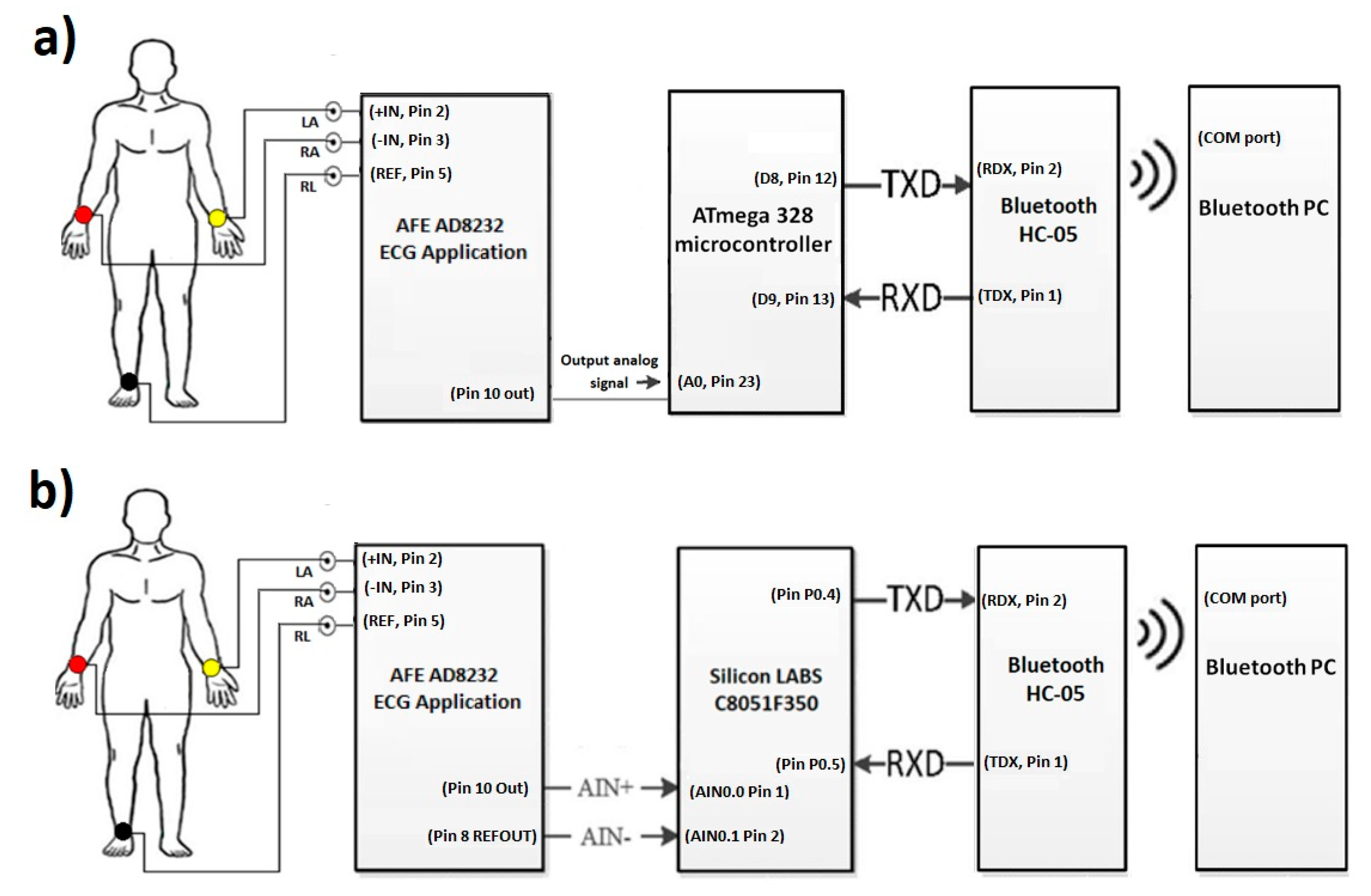
The objective of this paper was to identify and propose a solution for coping with motion artifacts in the ECG signal using a standard configuration in the AFE stage, but with variation of gain and ADC resolution in a portable ECG system. The alternative investigated in this work to solve this problem is to use a high precision ADC microcontroller (24 bits) that obtains a detailed ECG signal and reduce the gain of the system in the AFE design stage to tolerate a greater range of motion artifacts without saturating the system. The evaluated application was the cardiac monitor indicated in the Analog Devices’ data sheet [2]. To validate the proposal, two platforms were used for the acquisition of the ECG signal: (1) A 10-bit low-resolution ADC from Arduino Nano; and (2) 24-bit high-resolution ADC from C8051F350; and in both cases wireless transmission was through an HC-05 module (see Figure 1). This methodology is based on previous work [3] for rapid prototyping of ECG devices, using the AFE AD8232 and Bluetooth communication, but now centered in the motion artifacts problem. Figure 2 demonstrates the two microcontroller systems implementations.
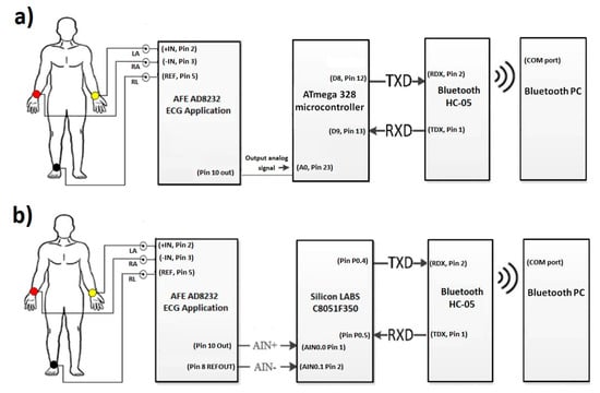
Figure 1.
(a) Low-resolution ECG system diagram with Arduino platform (ATmega328). (b) High-resolution system diagram for ECG monitoring with Silicon LABS platform (C8051F350).

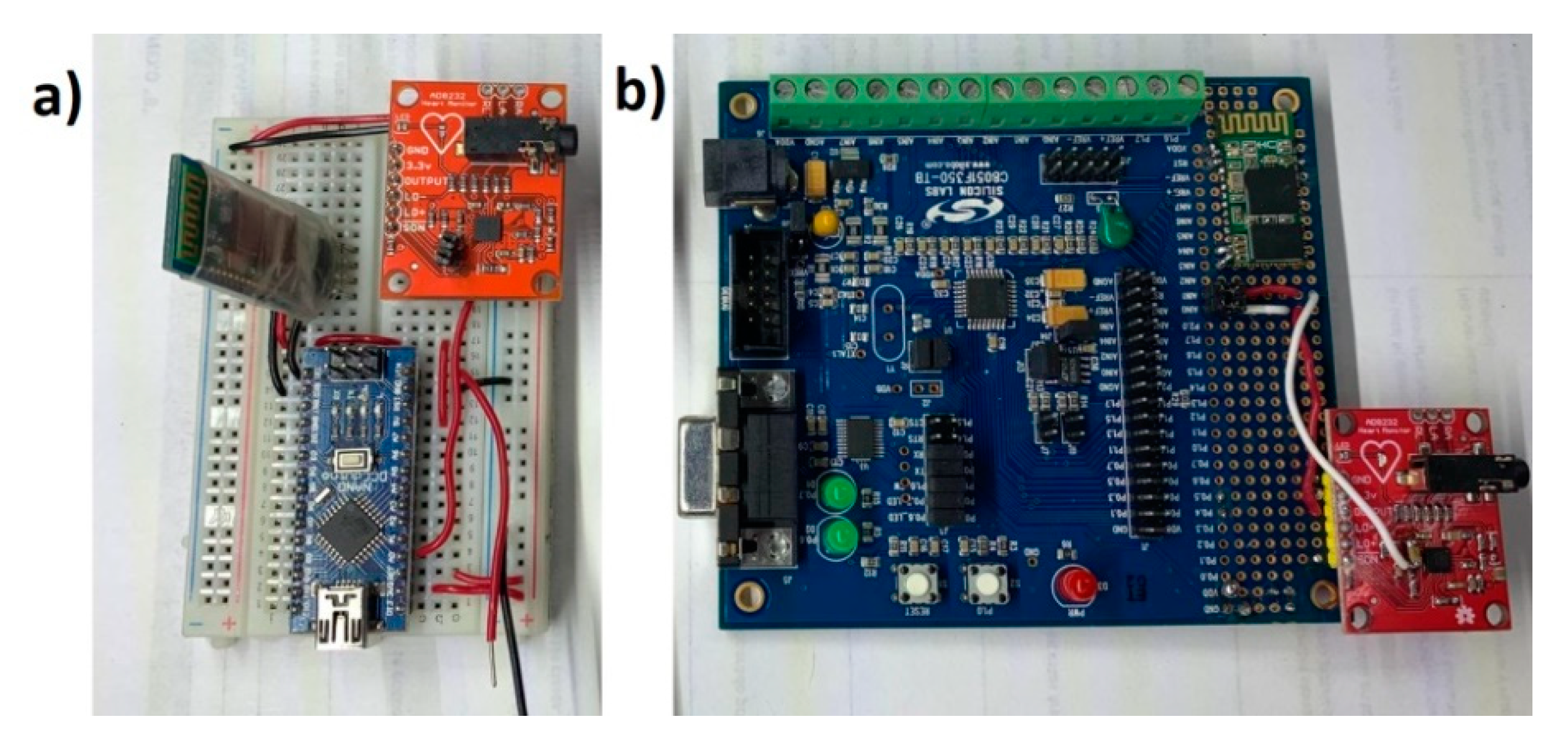
Figure 2.
(a) Low-resolution ECG system with Arduino platform (ATmega328). (b) High-resolution system for ECG monitoring with Silicon LABS platform (C8051F350). In both cases, the Sparkfun AD8232 module with minor modifications was used for the analog stage.
2. Materials and Methods
2.1. Test Subjects and Tests
For this methodology and experimentation, ECG signals of two human volunteers were captured: (1) volunteer A, healthy male, height 1.71 m, 27 years of age, weight of 105 kg, electrical axis of the position of the heart: 3 degrees, recorded lead DI: IN+ corresponding right arm (RA), IN− corresponding left arm (LA), and corresponding reference right leg (RL). (2) Volunteer B, healthy male, height 1.77 m, 23 years old, weight of 61 kg, electrical axis of the heart position: 120 degrees, DII registered lead: IN+ corresponding right arm (RA), IN− corresponding right leg (RL), and corresponding reference left arm (LA). The registered leads were chosen so that the QRS complex peak would show positive values. In this work, tests on resting state, stationary gait, and on a treadmill at different speeds were conducted on the human volunteers previously described, to investigate the problems and determine an effective way to cope with motion artifacts.
2.2. AFE Stage AD8232 Simulation of ECG Configuration
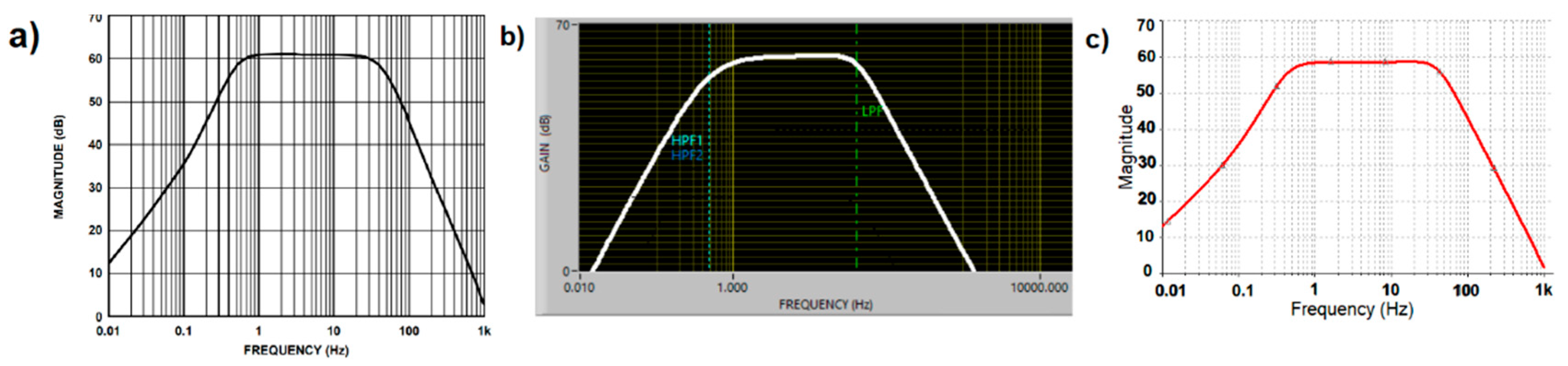
The analog ECG signal was provided by the AD8232 chip, using the hardware configuration present in the Sparkfun AD8232 module [4] which corresponded to the cardiac monitor application obtained from the AFE AD8232 data sheet [2], and whose frequency response is shown in Figure 3a. At this stage, simulation of the cardiac monitor configuration was obtained from two simulation software tools available. One was the NI Multisim (Figure 3b) and the other was the AD8232 filter design software (Figure 3c); this last software tool was provided by Analog Devices [5] as support for the modification of the filtering stage. In both simulations, a flat response from 0.5–40 Hz was demonstrated with a gain of 1100×. Although the response in the filtering stage can help to reduce motion artifacts by modifying the cutoff frequencies and response of the system, the intention now was to investigate the effect of the motion artifacts on a typical rest condition ECG configuration. The Sparkfun AD8232 module had a single supply operating voltage of 3.3 V and the microchip produced an internal reference level of 1.65 V, but no pin was provided in the board connector to the reference buffer. Battery power was used for safety and to avoid noise from AC adapters. The LED indicator of heartbeat rhythm was disabled.
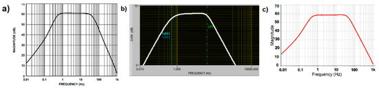
Figure 3.
Cardiac Monitor configuration frequency response (a) Frequency response indicated on datasheet. (b) Frequency response indicated by Filter Design software. (c) Frequency response simulated on NI Multisim software.
2.3. Low and High-Resolution Microcontroller System Characterization
The ECG configuration with variable gain was evaluated under two microcontroller systems of different ADC resolution. These microcontroller systems capture and transmit the ECG signal in real time to monitor the shape of the ECG waveform under motion artifacts and explore their ability to solve saturation problems. The analog precision and the conventional microcontroller systems specifications are shown in Table 1 for both of the microcontroller systems; a single supply hardware configuration was made with the Sparkfun AD8232 module (virtual ground), and a Bluetooth HC-05 module was used for data transmission.

Table 1.
Low and high resolution microcontroller systems: Arduino Nano (ATmega328) and Silicon LABS (C8051F350) platform characterization.
The conventional, low resolution system was a generic Arduino Nano board which employed the ATmega328 microcontroller with a single-ended input ADC of 10-bit resolution, ±2 LSB absolute accuracy, and a sampling frequency up to 15 KSPS at maximum resolution. For the ADC voltage reference (AREF), an external reference of 3.3 V was adjusted to the Arduino Nano, and represented the full range value, while the minimum analog input value represented GND. Under these conditions, a 10-bit resolution (3.3 V/1024 = 0.00322 V of LSB) was obtained. The chip had 32 kB of Flash memory and 2 kB of RAM.
For the analog precision, high-resolution system, the Silicon Labs C8051F350 platform was implemented with a fully-differential, 24-bit Sigma-Delta A/D (Bipolar Output Word Coding) with on-chip calibration capabilities. An external 2.5 V reference was used, that for practical purposes provided a differential input (AIN+–AIN−) full scale range of ±2.5 V. Under these conditions, a 24-bit resolution (5 V/224 ≈ 0.3 μV of LSB) was obtained. The root-mean-square noise (RMSN) increased at higher sampling rates, reducing the number of effective bits for conversion. The chip had only 8 kB of Flash and 768 bytes of RAM. There was a mismatch between the AD3282 signal output swing of ±1.65 V and the input voltage range of the ADC of ±2.5 V, this left a wasted conversion range. To capture the bipolar signal from the ECG, the output pin (OUT) of the AD8232 in the Sparkfun module was connected to the AIN0 input pin of the microcontroller and the AIN1 input was connected to the REFOUT of the AD8232. With these connections, the inherent offset in the analog ECG signal due to the single supply was eliminated.
2.4. Resolution, Sample Rate and Gain Settings
As mentioned, the proposal of this work was to evaluate two microcontroller systems with two different resolutions, but it mainly focused on the high-resolution solution. The 10-bit ADC platform maintained its noise level with the sampling frequency, but this low-resolution system presented a drawback when decreasing the gain, due to quantization noise and insufficient resolution; some detailed aspects of the ECG waveform were no longer present.
Assuming that the AD8232 amplifier’s output swing is coupled to the ADC’s input range, and the bandwidth is already set, then if the gain is increased on the amplifier, an ADC with its fixed number of bits can resolve smaller details of the biosignal (provide higher resolution). However, motion artifacts will shoot the baseline faster towards saturation because the system’s gain was increased. Whereas, if the number of bits of the ADC is increased without increasing the system’s gain, or even when decreasing the gain, good resolution is maintained without promoting sensitivity due to motion artifacts. The usage of a 24-bit ADC is a way to increase gain without worrying about fast clipping by motion artifact, while having supply voltages of 3.3 V or less. The production of AFE microchips and high-precision microcontrollers with a low power supply voltage, is a way in which semiconductor companies have responded to this challenge of having a gain lower than 200× in the AFE. For example, at the output of a low gain AFE, the peak-to-peak ECG signal will not be seen as 1 V, but probably at 200 mV; because the ADC has 24 bits, it would look even better than 1 V with a 10–12-bit ADC. That is the reason of the trend towards 24 bits, to compensate for motion artifacts, and lower supply voltages, so that the batteries last longer.
Meanwhile, in the high-resolution Silicon Labs platform, a software routine to characterize the development board was executed. Capturing 128 samples of the 24-bit ADC, for a noise measurement, the inputs labeled AIN0 and AIN1 were connected to analog ground (AGND) at the terminal block of the board. The standard deviation (σ) of a sample set is equivalent to the effective RMS noise of the conversion system. This is equivalent to a Signal-to-Noise ratio SNRdB = 20 log10(223/σ), or to equivalent effective bits as 6 dB/bit. Tests were carried out that indicated that when increasing the sampling frequency, the SNR decreased, therefore the noise in the signal increased. For a frequency of 120 Hz, the calculated RMS noise was 64.54 digital units, the SNR was 102.45 dB, and the effective bits were 17.08 instead. At 360 Hz, the RMSN was 851.06 digital units, the SNR decreased to 79.87 dB and the effective bits were 13.31 (see Table 2). Considering these characterization values from the C8051F350 board, it appears that ECG signal capture is best when configured at a 180 Hz sample rate for the Sparkfun AD8232 module’s built-in heart monitor setup at an adjustable gain of 100× and 1100×.
Table 2.
Noise, Signal-to-Noise (SNR), and Resolution at different sample rates using the Silicon Lab C8051F350 microcontroller.
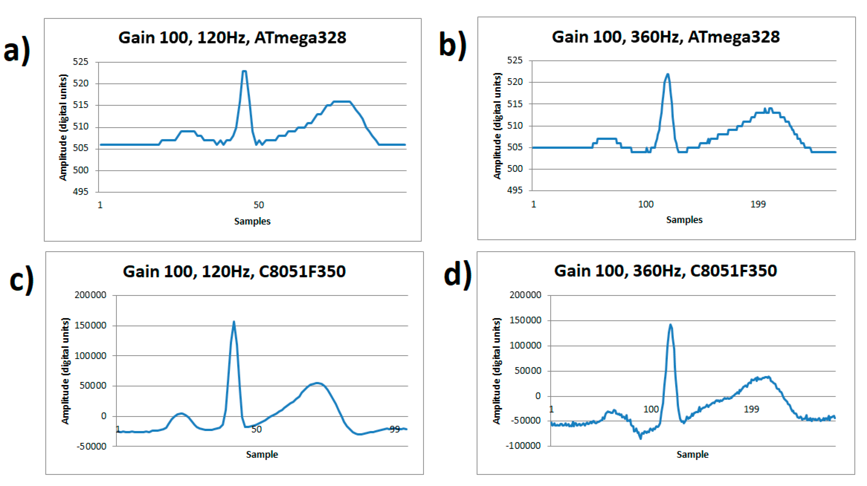
Figure 4 visually demonstrates the dominating noise at a low gain of 100×, with a detailed signal capture of an ECG cycle. The number of bits of the A/D converter in the ATmega328 impose the resolution quantification error greater than the order of the input noise. The noise level appears the same at any rate, see Figure 4a,b, and the quantization noise dominates. Meanwhile on the C8051F350 microcontroller, high sample rates do affect the signal when using a low gain of 100×, even though there is enough resolution to detail the ECG waveform. This comparison is shown on Figure 4c at a sample of 120 Hz showing a good signal quality, but in Figure 4d it shows increased noise due to the resolution drop in the conversion (13 effective bits) at a sampling of 360 Hz.
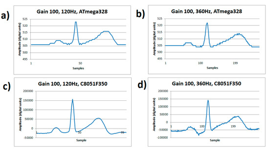
Figure 4.
ECG signal from human volunteer A, (lead I). (a) Gain 100×, sample rate 120 Hz on ATmega328 microcontroller, (b) Gain 100x, sample rate 360 Hz on ATmega328 microcontroller, (c) Gain 100×, sample rate 120 Hz on C8051F350 microcontroller, (d) Gain 100×, sample rate 360 Hz on C8051F350 microcontroller.
2.5. ECG Signal Acquisition
After defining the filtering stage, the Sparkfun board and breadboard cardiac monitor configuration in the AFE stage were implemented. Using the Arduino Nano and silicon LABS platforms; Bluetooth transmission with the HC-05 module in board mode was incorporated. The software to receive and display the signal was the Arduino integrated development environment (IDE) with its add-ons, Serial Monitor, communication (COM) ports, and Serial Plotter. The Bluetooth module and COM ports were configured at a baud rate of 115,200 bps and the sample rate for both microcontroller platforms was set to 180 Hz. Signals were obtained for high-resolution and low-resolution microcontrollers, with 100× and 1100× gain respectively.
3. Results and Discussion
The prototypes developed were single-lead electrocardiographs with a bandwidth of 0.5–40 Hz and adjustable gains of 100× and 1100×: (1) with a high resolution 24-bits based on a C8051F350 microcontroller, and (2) with a low resolution 10-bits based in a generic Arduino Nano board. Both prototypes were able to sample to 1000 Hz (samples/sec) without loss of data in serial Bluetooth transmission.
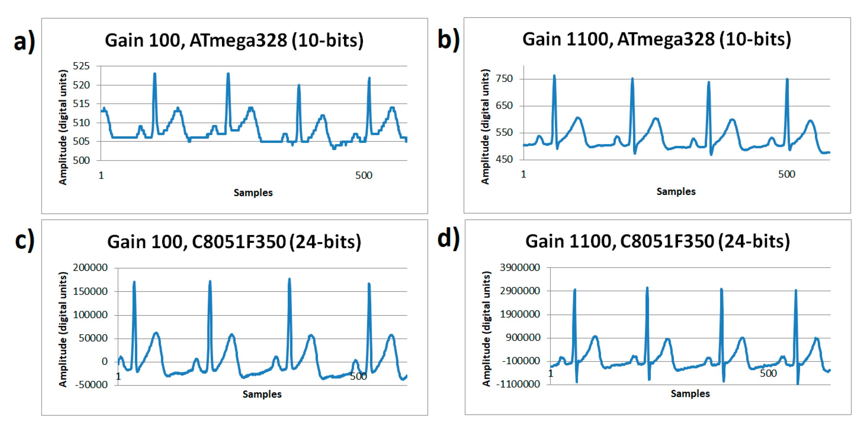
The ECG signals shown in Figure 5 were captured on resting conditions, sampled with a rate of 180 Hz, for two different gains of the microcontroller systems. On Figure 5a, working with a gain of 100× using the ATmega328 microcontroller’s ADC with a 10-bit resolution showed an amplitude range of 19 digital units; Figure 5b working with a gain of 1100× using the ATmega328 microcontroller’s ADC with a 10-bit resolution showed an amplitude range of 268 digital units. In Figure 5c, working with a gain of 100× using the C8051F350 microcontroller’s ADC with a 24-bit resolution showed an amplitude range of 208,030 digital units; and Figure 5d, working with a gain of 1100× using the C8051F350 microcontroller’s ADC with a 24-bit resolution showed an amplitude range of 4,135,329 digital units. During rest conditions, it was evidenced that low gain turns into a problem when working on low-resolution systems (10 bits, Figure 5a), however gain is not as relevant when using high-resolution systems. Figure 5b shows that a 1100× gain on a 10-bit system is acceptable and solves the ECG wave details visualization needs, however this does not occur on Figure 5a. Furthermore, the increase in gain makes the negative peak (S point) of the QRS complex emerge in detail, for any resolution system; somehow the increased gain demonstrated the information lost in the quantizer process.
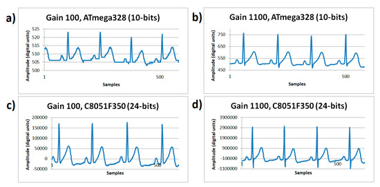
Figure 5.
ECG signals sampled at 180 Hz rate from human volunteer A on resting state (lead I). (a) Gain 100×, ATmega328 (10-bits) with 100× gain. (b) ATmega328 (10-bits) with 1100× gain. (c) C8051F350 (24-bits) with 100× gain. (d) C8051F350 (24-bits) with 1100× gain.
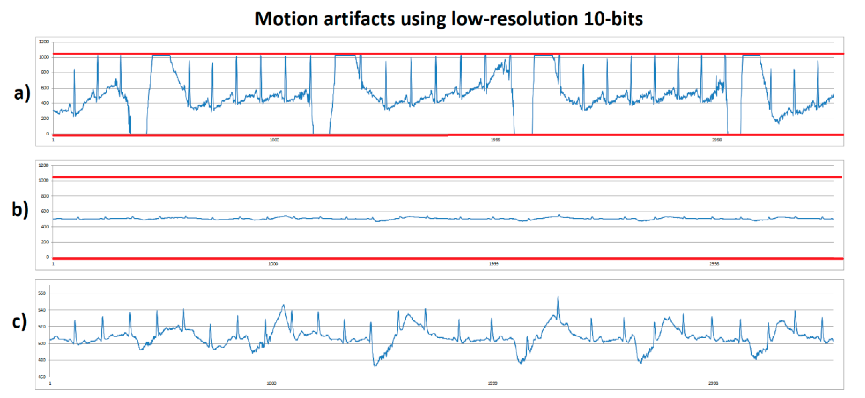
Non resting tests were implemented to investigate how the motion artifacts worked to reach system saturation. Human volunteer B performed a stationary gait with fast sudden movement. This consisted of the volunteer walking slowly without moving from their place, for approximately four seconds, and then suddenly moving their arms to produce a motion artifact. On Figure 6, the low-resolution (10 bits) system was used. Figure 6a shows the system with 1100× gain on which red lines correspond to the lower and upper saturation limits of 0 and 1023, respectively. In this case, it was observed that, when making sudden movement, system’s saturation was reached on lower and upper limits. Figure 6b shows an ECG signal obtained with 100× gain—this signal looks small because the same axis scale as in Figure 6a was used to compare. It was observed that a higher margin was present to prevent system saturation. Figure 6c corresponds to the same signal as in Figure 6b, but scaled out to observe the details of the signal, however because it is still a low-resolution with low gain, the ECG signal did not supply enough information, although system saturation due to motion artifacts was solved.
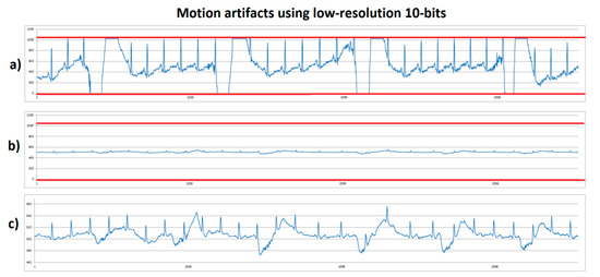
Figure 6.
ECG signals from human volunteer B (lead DII) at stationary gait with a fast sudden movement using low-resolution 10-bits platform. (a) Motion artifact causing saturation limits reaching (red lines) using 1100× gain. (b) Motion artifact without saturation using 100× gain with scale 0-1023. (c) Motion artifact without saturation using 100x, with scale zoom.
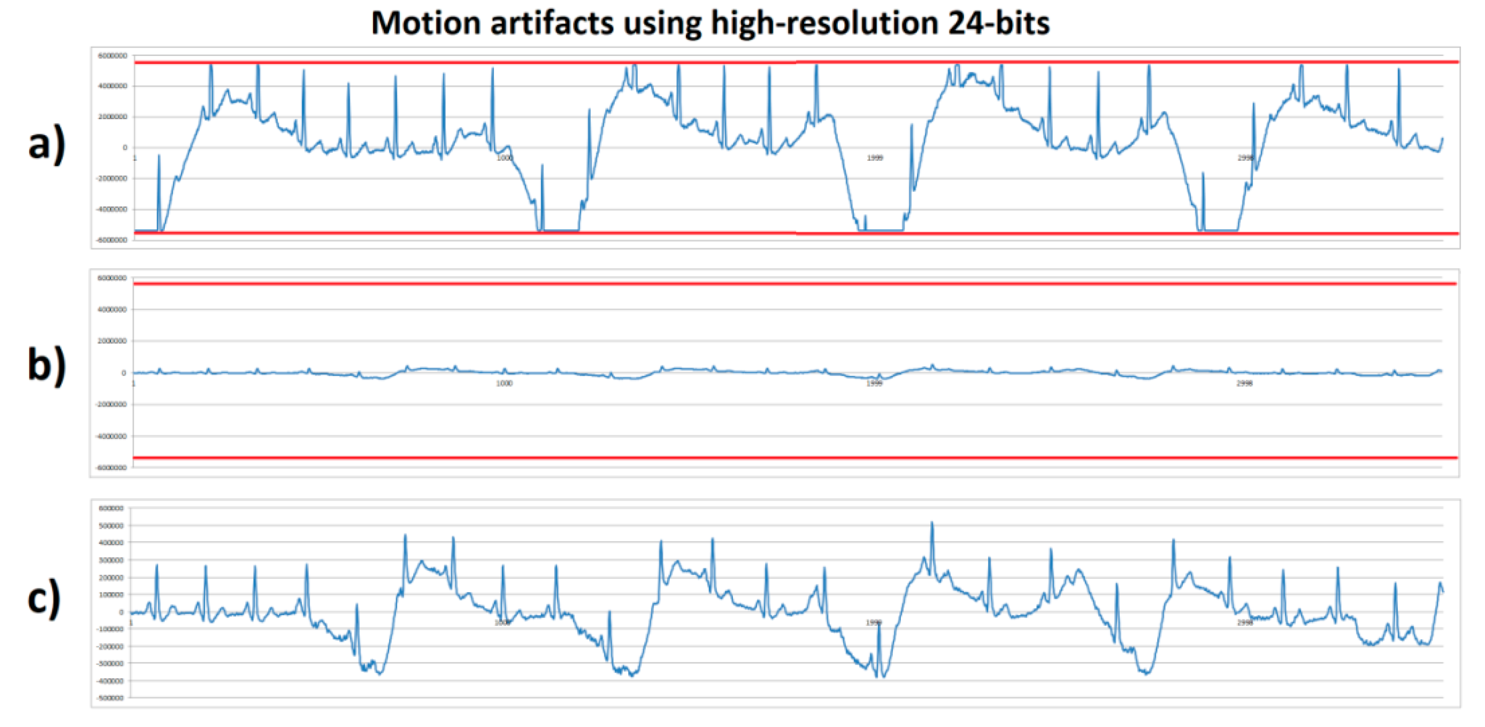
The same stationary gait with a fast sudden movement test was executed by human volunteer B using the high-resolution (24 bits) system with 100× and 1100× gain. Figure 7a shows the system with 1100× gain that, during motion artifact, reached saturation at the lower and upper limits with an amplitude of ±5,339,000 digital units (red lines); these saturation lines corresponded to the minimum and maximum output of the AFE converted to the 24-bit ADC levels. Figure 7b shows the system with 100× gain and a vertical axis scale from ±6,000,000. In comparison with Figure 7a, it can be observed that the signal’s amplitude with 100× gain did not exceed the ±500,000 range, therefore, a higher range without reaching saturation limits (red lines) was obtained. Figure 7c shows the same signal as in Figure 7b, but with a lower vertical axis scale, and unlike in Figure 6c, the high-resolution system allowed the obtention of a detailed ECG signal without reaching the system’s saturation. From this experiment and the previous one shown in Figure 6, the motion artifacts introduced a displacement of ±1.9 mV from a stable baseline at the input of the AFE amplifier. Considering this motion artifact amplitude and a 1100× gain, the output would be 2.2 V. Because the AFE circuit was supplied with 3.3 V (±1.65 V range), the motion artifact’s amplitude left only 0.55 V remaining for the ECG signal before reaching saturation. Typically, the ECG output signal from the AD8232 microchip varied from 0.8 V to 1 V using a 1100× gain. This was not enough for the ECG signal expression without causing system saturation. Considering the motion artifact amplitude and the output voltage limit, a gain of 587× was the maximum gain before causing saturation.

Figure 7.
ECG signals from human volunteer B (lead DII) at stationary gait with a fast sudden movement using high-resolution 24-bits platform. (a) Motion artifact causing saturation limits reaching (red lines) using 1100× gain. (b) Motion artifact without saturation using 100× gain with scale ±6,000,000. (c) Motion artifact without saturation using 100× gain, with scale zoom.
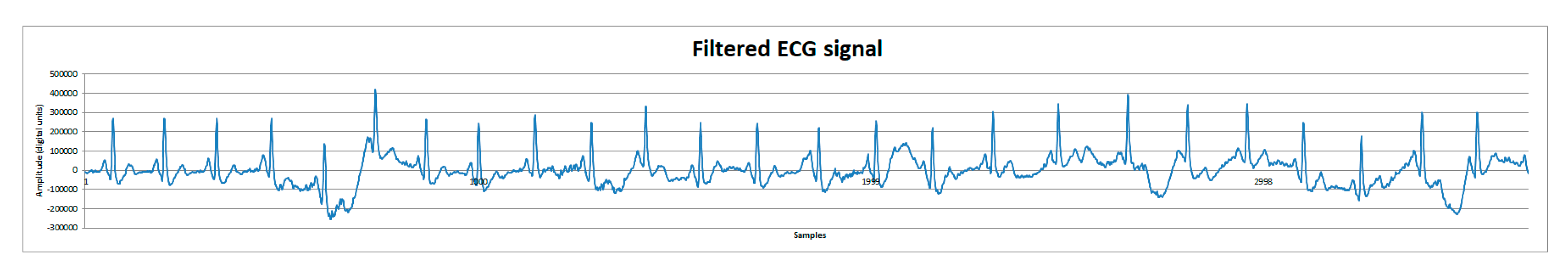
Finally, post-processing tests using MATLAB’s Filter Designer application [6] were made to reduce motion artifacts. Signals were first analyzed applying a fast Fourier transform to identify possible motion artifact frequencies. Subsequently, a second order Butterworth filter was used to attenuate the motion artifact frequencies of about 1 Hz and below, and the motion artifact was considerably reduced. On Figure 8, the filtered signal can be observed and compared to Figure 7c.
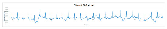
Figure 8.
ECG signal from human volunteer B (lead DII). Filtered ECG signal with a second order Butterworth filter to reduce motion artifacts.
4. Conclusions
The structure of a high-resolution and low-resolution microcontroller system has been implemented for the investigation of wearable ECG sensor motion artifacts effects. Arduino Nano and Silicon Labs platforms were characterized for different sampling rates and RMS noise. The low-resolution (10-bits) Arduino platform exhibited a large quantification error in resting conditions that hid the presence of input noise introduced by both the electrode–skin contact and the amplifier electronics at any sampling rate; however the high-resolution (24-bits) silicon labs platform showed a higher susceptibility to RMS input noise as sampling rate increased (see Table 2 and Figure 4). It was observed that, in a resting state, the Arduino platform solved the ECG signal’s waveform properly, but after motion tests this system showed sensibility to saturation due to motion artifacts when using 1100× gain. When lowering the system’s gain to 100×, saturation problem was solved but low resolution did not supply a detailed ECG signal. Silicon Labs platform with 1100× gain showed a detailed signal but was sensitive to saturation due to motion artifacts. However, this problem was solved by lowering the system’s gain to 100×, which prevented the system from reaching saturation due to motion artifacts, and showed a detailed ECG signal. The gain of the analog chain must be low to accommodate voltage fluctuations without saturation of the A/D converter. A gain of 587× was calculated as the highest possible without producing saturation. A high number of bits (24 bits) of the A/D converter could be used with a low gain to maintain signal detail.
Other tests on a treadmill at different gait speeds and a gain of 100× were made, but the ECG signal was significantly distorted without saturating. Low gain and higher ADC resolution helped to reduce the effect of the motion artifacts, but in addition to analog cutoff frequencies and classical post-processing, the usage of other hardware designs and advanced software post-processing is necessary to entirely solve the motion artifact problem, in order to recover the single ECG signal from the acquired noisy signal.
Author Contributions
Conceptualization and methodology, M.B.-Z., E.A.-C. and R.L.-A.; hardware, software, and validation, D.C.-G., E.A.-C. and M.B.-Z.; writing—original draft preparation, writing—review and editing, J.P.G.-V., D.C.-G. and M.B.-Z.; and final paper review, M.A.R. and R.L.-A. All authors have read and agreed to the published version of the manuscript.
Funding
This research was funded by CONACyT CVU: 763230 (D.C.-G.) and CVU: 1055121 (E.A.-C.)
Acknowledgments
We thank CONACyT for the scholar fellowship of the authors D.C.-G. and E.A.-C.
Conflicts of Interest
The authors declare no conflict of interest.
References
- Digikey. Design a High-Resolution ECG with a Fully Differential Amplifier and High-Resolution ADC. Available online: https://www.digikey.com/en/articles/design-a-high-resolution-ecg-with-a-fully-differential-amplifier-and-high-resolution-adc (accessed on 9 October 2020).
- Analog Devices. Single-Lead Heart Rate Monitor Front End, Massachusetts, USA, 2012–2017. Available online: http://www.analog.com/media/en/technical-documentation/data-sheets/AD8232.pdf (accessed on 9 October 2020).
- Bravo-Zanoguera, M.; Cuevas-González, D.; Reyna, M.A.; García-Vázquez, J.P.; Avitia, R.L. Fabricating a Portable ECG Device Using AD823X Analog Front-End Microchips and Open-Source Development Validation. Sensors 2020, 20, 5962. [Google Scholar] [CrossRef] [PubMed]
- SparkFun. Single Lead Heart Rate Monitor AD8232. Available online: https://www.sparkfun.com/products/12650 (accessed on 5 October 2020).
- AD8232 Filter Design (Open Source). 2017. Available online: https://www.analog.com/en/products/ad8232.html#product-tools (accessed on 9 October 2020).
- Filter Design (MATLAB). 2018. Available online: https://la.mathworks.com/discovery/filter-design.html (accessed on 25 October 2020).
Publisher’s Note: MDPI stays neutral with regard to jurisdictional claims in published maps and institutional affiliations. |
© 2020 by the authors. Licensee MDPI, Basel, Switzerland. This article is an open access article distributed under the terms and conditions of the Creative Commons Attribution (CC BY) license (https://creativecommons.org/licenses/by/4.0/).