Proceeding Paper

Design of an Embedded Broadband Thermoelectric Power Sensor in the InP DHBT Process †

Ferdinand-Braun-Institut, Leibniz-Institut für Höchstfrequenztechnik (FBH), 12489 Berlin, Germany
*
Author to whom correspondence should be addressed.
Presented at the 7th Electronic Conference on Sensors and Applications, 15-30 November 2020; Available online: https://ecsa-7.sciforum.net/.
Eng. Proc. 2020, 2(1), 10; https://doi.org/10.3390/ecsa-7-08206
Published: 14 November 2020
(This article belongs to the Proceedings of 7th International Electronic Conference on Sensors and Applications)

Abstract

:
The thermopile-based thermoelectric sensor has emerged as an important approach for microwave power measurement. It employs the Seebeck effect, which converts the microwave power into the heat and generates the thermovoltage. However, the output thermovoltage generally exhibits a frequency-dependent feature, which affects measurement accuracy. Besides, the low sensitivity of the current existed planar thermopile-based sensor constrains its further application. This is mainly caused by the heat loss of the substrate in the conversion process of microwave power-heat-electricity. In this paper, a novel embedded power sensor based on the indium phosphide (InP) double heterojunction bipolar transistor (DHBT) process is presented. The thermopile is embedded in the benzocyclobutene (BCB) to prevent the heat loss, and the embedded structure also enables this sensor to eliminate the need for microelectromechanical system (MEMS) technology. The electromagnetic simulation by ANSYS high frequency structure simulator (HFSS) and thermal simulation by ANSYS Steady-State Thermal are combined to evaluate the sensor performance. The result shows that the output voltage increases with the input power linearly, and the proposed sensor is almost independent of the microwave frequency. A sensitivity of l.07 mV/mW has been achieved up to 200 GHz, with the port return loss lower than −15.8 dB.

1. Introduction

Microwave power measurement plays an indispensable role in wireless communication. At present, there are many alternative sensor types that are available for power detection, such as a thermoelectric sensor, thermistor sensor, diode sensor, and so on [1]. Among these different approaches, the thermoelectric sensor arises with advantages of passive operation (no need for bias supply), excellent linearity, high dynamic range, broadband performance, and remarkably, compatibility with monolithic microwave integrated circuit (MMIC) technology. One of the promising topics to be investigated is measuring the power delivered from an MMIC amplifier directly on-chip, which has the advantages of low insertion loss, low-cost fabrication, and continuous power monitoring as well. These merits give it a wide variety of uses, such as gain control and circuit protection.
The first termination-type thermoelectric power sensor with an MMIC process based on the Seebeck effect was introduced in 1996 [2], which indirectly measured the power dissipated on 50 ohms of load. After that, to improve the sensitivity, a thermoelectric microwave power sensor by bulk etching MEMS technology was presented [3]. A cavity was etched from the back of the substrate, under the thermopile and resistors. However, the realization of MEMS technology increases the cost and difficulty of the following package. Moreover, a sandwich-type power sensor was proposed, where a simple Si3N4 dielectric layer takes the place of the back cavity by MEMS technology [4]. However, the improvement of sensitivity is not enough, thus limiting its performance and further application.
To further increasing the sensitivity, the embedded sensor structure in the InP DHBT process was designed. The very low thermal conductivity of BCB ensures heat preservation around the thermopile as much as possible, which leads to a reduced heat loss. Compared to other techniques, this method has the advantage of wide frequency range and high sensitivity. What is more, the cost and complexity of the process will be reduced without the need for MEMS. To the best of the author’s knowledge, there is no literature about such a thermoelectric power sensor that fully compatible with the InP DHBT process at the Ferdinand-Braun-Institute (FBH) so far.

2. Principle and Modeling

A thermocouple is composed of two dissimilar materials. When there is a temperature difference between the two ends, according to the Seebeck Effect, the thermocouple converts the temperature difference proportional to the voltage difference. Several series-connected thermocouples make up the thermopile, to superpose thermovoltage of each thermocouple [5,6]. The Seebeck voltage can be obtained as:
V s e e b e c k = ( α a α b ) · i N ( T h o t T c o l d )
Where α a and α b are the Seebeck coefficients of the two dissimilar materials, T h o t and T c o l d are the temperatures of the hot and cold ends, respectively, and N is the number of the cascaded thermocouples. Therefore, the sensitivity of the proposed sensor is represented as:
S = V s e e b e c k / P i n
Here P i n is the input power.
The proposed power sensor is designed in the InP DHBT MMIC process [7], the simplified layer stack is shown in Figure 1.
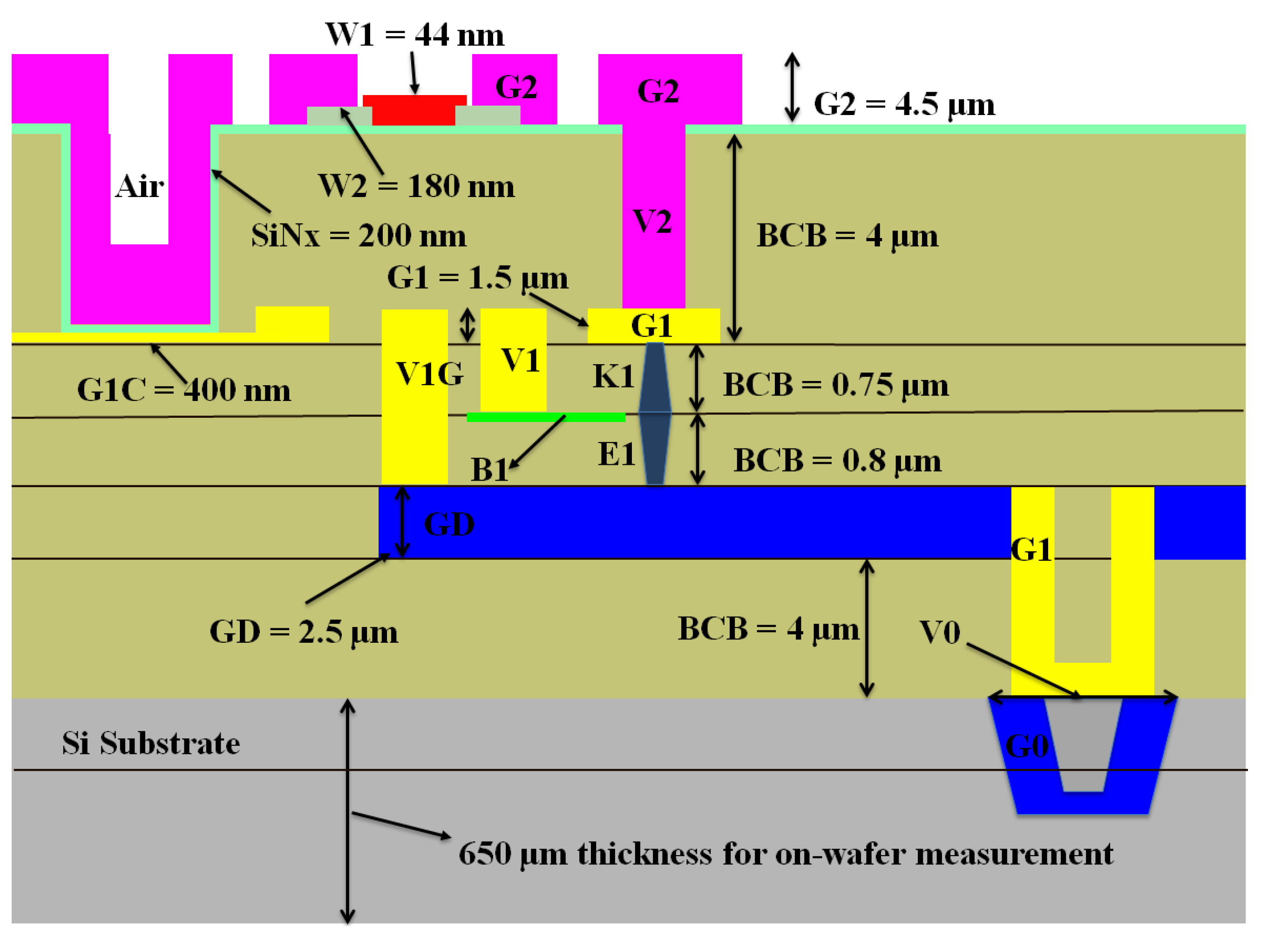
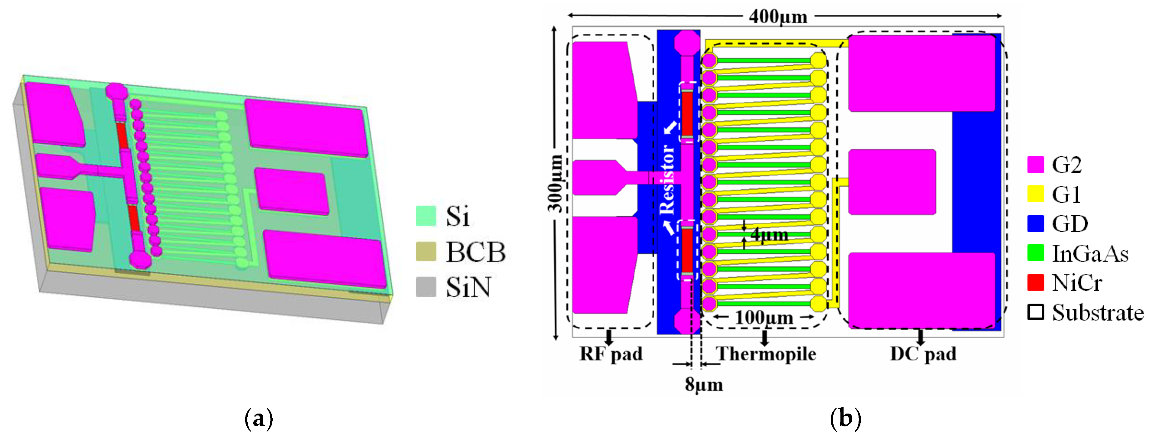
  • Three gold metal layers are embedded in BCB, including G1 (1.5 µm), G2 (4.5 µm), and GD (2.5 µm) that serves, respectively, as interconnects, microstrip line, and the ground plane.
  • The thickness of nickel-chrome (NiCr) thin-film resistors (TFRs) is 44 nm, with a sheet resistance on 25 Ω/sq [8].
  • The 15 thermocouples consist of G1 metal and 30 nm P-In0.53Ga0.47As. The P-In0.53Ga0.47As locates at the B1 layer with a doping level of 5×1019cm-3. The corresponding Seebeck coefficient is calculated based on [9].
The geometry of the embedded thermoelectric power sensor is shown in Figure 2a. Figure 2b gives the detailed dimension parameters of the proposed sensor. The microwave power is fed-in by the RF pad and then dissipated on the two 100 Ω NiCr TFRs that are connected in parallel. The size of the selected TFR is 10 μm × 40 μm.
The generated Joule heat transfer to surroundings by the means of heat conduction, convection and radiation. When a steady state has been reached, a heat distribution of the embedded thermoelectric power sensor emerges, which leads to a temperature difference along the thermopile. Finally, the generated thermovoltage is measured by the DC pad.
The thermal parameters used in the simulation are illustrated in Table 1.

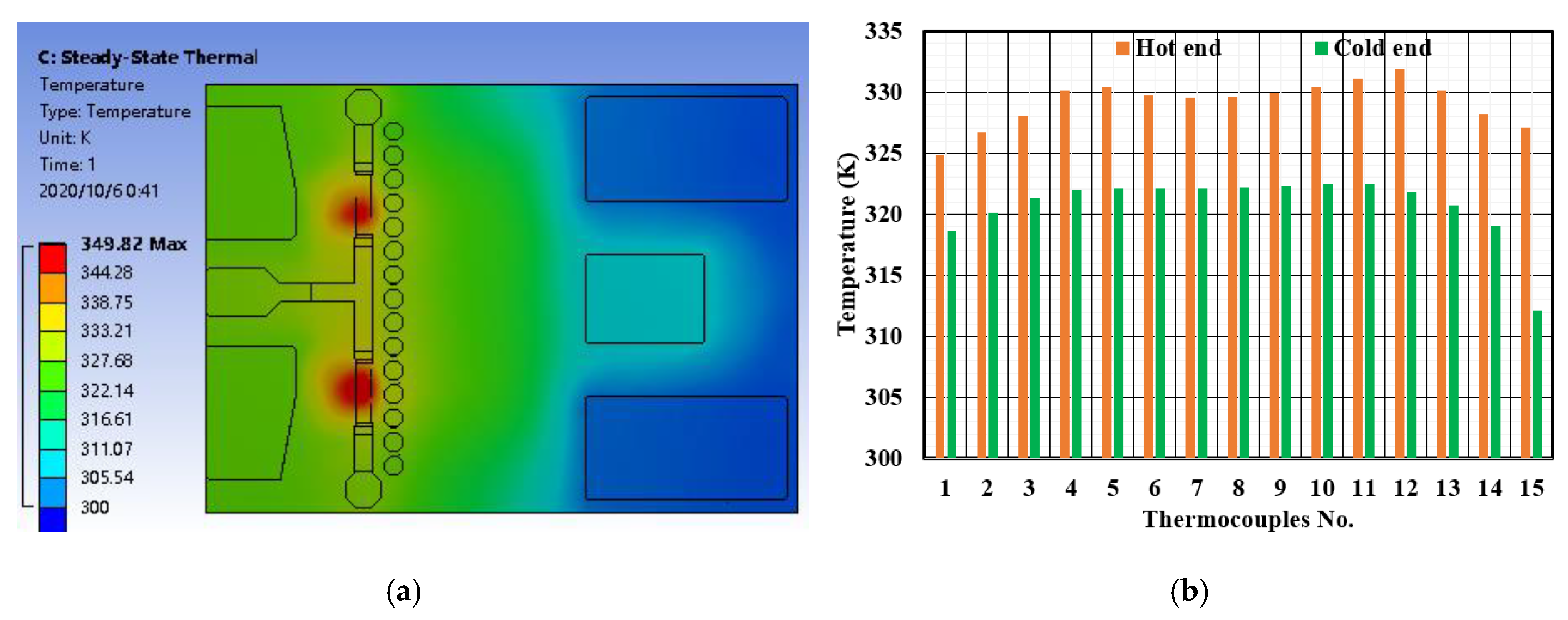
3. Simulation Result

The port reflection performance of the embedded power sensor that simulated by ANSYS HFSS is given in Figure 3, the return loss is lower than -15.8 dB up to 200 GHz. Less than 2.6% of the power is reflected.
Next, the electromagnetic result from ANSYS HFSS is imported to ANSYS Steady-State Thermal component to obtain the thermal result. As in Figure 4a, given 10 mW input power at 20 GHz, the two TFRs have the highest temperature of 349.82 K. The temperature at the hot end/cold end of each thermocouple is shown in Figure 4b.
According to the equation (1), the calculated output voltages with 10 to 100 mW input power are shown in Figure 5a. The sensitivities versus frequency from 10 to 200 GHz are calculated by Equation (2), as shown in Figure 5b.
The output voltages increase with input power linearly, there is a very slight drop when the frequency increases from 10 to 200 GHz. Given a 10-mW input power, the sensitivities of the power sensor are 1.14 mV/mW at 10 GHz and 1.07 mV/mW at 200 GHz. It can be concluded that the proposed sensor almost shows the frequency-independent characteristic.
Table 2 gives the comparison of thermoelectric power sensors based on different technology, it is apparent that the embedded thermoelectric power sensor provides better sensitivity and wider working frequency. Furthermore, the proposed sensor achieves low-cost fabrication without MEMS.

4. Discussion

In this work, a design of the embedded broadband thermoelectric power sensor in the InP DHBT process is presented. The electromagnetic simulation by HFSS and thermal simulation by Steady-state thermals are combined to obtain an accurate result. The proposed sensor can measure power directly on-chip with minimum impact on the system. The port return loss is lower than −15.8 dB up to 200 GHz while the overall sensitivity is higher than 1.07 mV/mW. The output voltage increases with the input power linearly, and the embedded sensor is almost independent of the microwave frequency. In future works, the fabrication of the proposed sensor and measurement results will be reported. Furthermore, a 3D model of the proposed sensor will be given to describe the fabricated sensor and assist sensor optimization.

Author Contributions

The authors contributed equally to this work.

Funding

This research received no external funding.

Conflicts of Interest

The authors declare no conflict of interest.

References

  1. Yan, J.; Yi, Z.; Liao, X. High dynamic range microwave power sensor with thermopile and curled cantilever beam. Electron. Lett. 2015, 51, 1341–1343. [Google Scholar] [CrossRef]
  2. Dehe, A.; Fricke-Neuderth, K.; Krozer, V. Broadband Thermoelectric Microwave Power Sensors using GaAs Foundry Process. In Proceedings of the 2002 IEEE MTT-S International Microwave Symposium Digest (Cat. No.02CH37278), Seattle, WA, USA, 2–7 June 2002; Volume 3, pp. 1829–1832. [Google Scholar] [CrossRef]
  3. Yi, Z.; Liao, X. 3D Model of the Thermoelectric Microwave Power Sensor by MEMS technology. In Proceedings of the 2015 IEEE SENSORS, Busan, Korea, 1–4 November 2015; Volume 1, pp. 1–4. [Google Scholar]
  4. Zhang, Z.; Guo, Y.; Li, F.; Gong, Y.; Liao, X. A Sandwich-Type Thermoelectric Microwave Power Sensor for GaAs MMIC-Compatible Applications. IEEE Electron Device Lett. 2016, 37, 1639–1641. [Google Scholar] [CrossRef]
  5. Graf, A.; Arndt, M.; Gerlach, G. Seebeck’s effect in micromachined thermopiles for infrared detection. A review. Est. J. Eng. 2007, 13, 338–353. [Google Scholar]
  6. Dibra, D.; Stecher, M.; Lindemann, A.; Lutz, J.; Kadow, C. Seebeck difference-temperature sensors integrated into smart power technologies. In Proceedings of the 2008 20th International Symposium on Power Semiconductor Devices and IC’s, Barcelona, Spain, 14–18 June 2009; pp. 216–219. [Google Scholar] [CrossRef]
  7. Weimann, N.G.; Stoppel, D.; Schukfeh, M.I.; Hossain, M.; Al-Sawaf, T.; Janke, B.; Doerner, R.; Sinha, S.; Schmückle, F.-J.; Krüger, O.; et al. SciFab—A wafer-level heterointegrated InP DHBT/SiGe BiCMOS foundry process for mm-wave applications. Phys. Status Solidi 2016, 213, 909–916. [Google Scholar] [CrossRef]
  8. Stoppel, D.; Ostermay, I.; Hrobak, M.; Shivan, T.; Hossain, M.; Reiner, M.; Thiele, N.; Nosaeva, K.; Brahem, M.; Krozer, V.; et al. NiCr resistors for terahertz applications in an InP DHBT process. Microelectron. Eng. 2019, 208, 1–6. [Google Scholar] [CrossRef]
  9. Dehe, A.; Pavlidis, D.; Hong, K.; Hartnagel, H. InGaAs/InP thermoelectric infrared sensor utilizing surface bulk micromachining technology. IEEE Trans. Electron Devices 1997, 44, 1052–1059. [Google Scholar] [CrossRef]
Figure 1. Layer description of the InP DHBT MMIC process.
Engproc 02 00010 g001
Figure 2. (a) Schematic overview of the proposed sensor; (b) Dimension parameters of the proposed sensor.
Engproc 02 00010 g002
Figure 3. The simulated return loss of the proposed sensor.
Engproc 02 00010 g003
Figure 4. When given 10 mW input at 20 GHz: (a) Temperature distribution in the sensor chip; (b) Temperature at the hot end/cold end of each thermocouple.
Engproc 02 00010 g004
Figure 5. (a) Output voltage versus input power from 10 to 100 mW; (b) Under 10 mW input power, the sensitivity versus frequency between 10 and 200 GHz.
Engproc 02 00010 g005
Table 1. Parameters in the electro-thermal simulation.
ParameterValue
Thermal conductivity (Au) 315   W / ( m · k)
Thermal conductivity (BCB) 0.29   W / ( m · k)
Thermal conductivity (SiN) 30   W / ( m · k)
Seebeck coefficient (Au)1.5 μV/K
Seebeck coefficient (In0.53Ga0.47As)90 μV/K
Ambient temperature300 K
Table 2. Comparison of the different thermoelectric power sensor.
This work[2][3][4]
Sensitivity (mV/mW)1.14 @ 10 GHz0.55 @ 10 GHz0.27 @ 10 GHz0.09 @ 10 GHz
Frequency RangeUp to 200 GHzUp to 26 GHzUp to 10 GHzUp to 20 GHz
Need of MEMSNoNoYesNo
Publisher’s Note: MDPI stays neutral with regard to jurisdictional claims in published maps and institutional affiliations.

