1. Introduction
Continuous monitoring is actively used in the medical practice as it allows for the constant monitoring of biomarkers. This facilitates timely and accurate diagnosis, which is followed by medical treatment. Genome sequencing is a method that deciphers huge amounts of data that are present in a DNA samples and is vital for detecting mutations and pathogens [
1]. The analyte can be studied with the utilisation of a biosensor, a device which converts biochemical reaction into readable signal [
2].
There are many methods of sample manipulation [
3] used in laboratories, one of which is microfluidics. It has gained significant interest over recent years and has become an integral part of modern biosensors [
4]. Among the many advantages of microfluidics are rapid reaction and ultra-low detection limit of the analyte [
5].
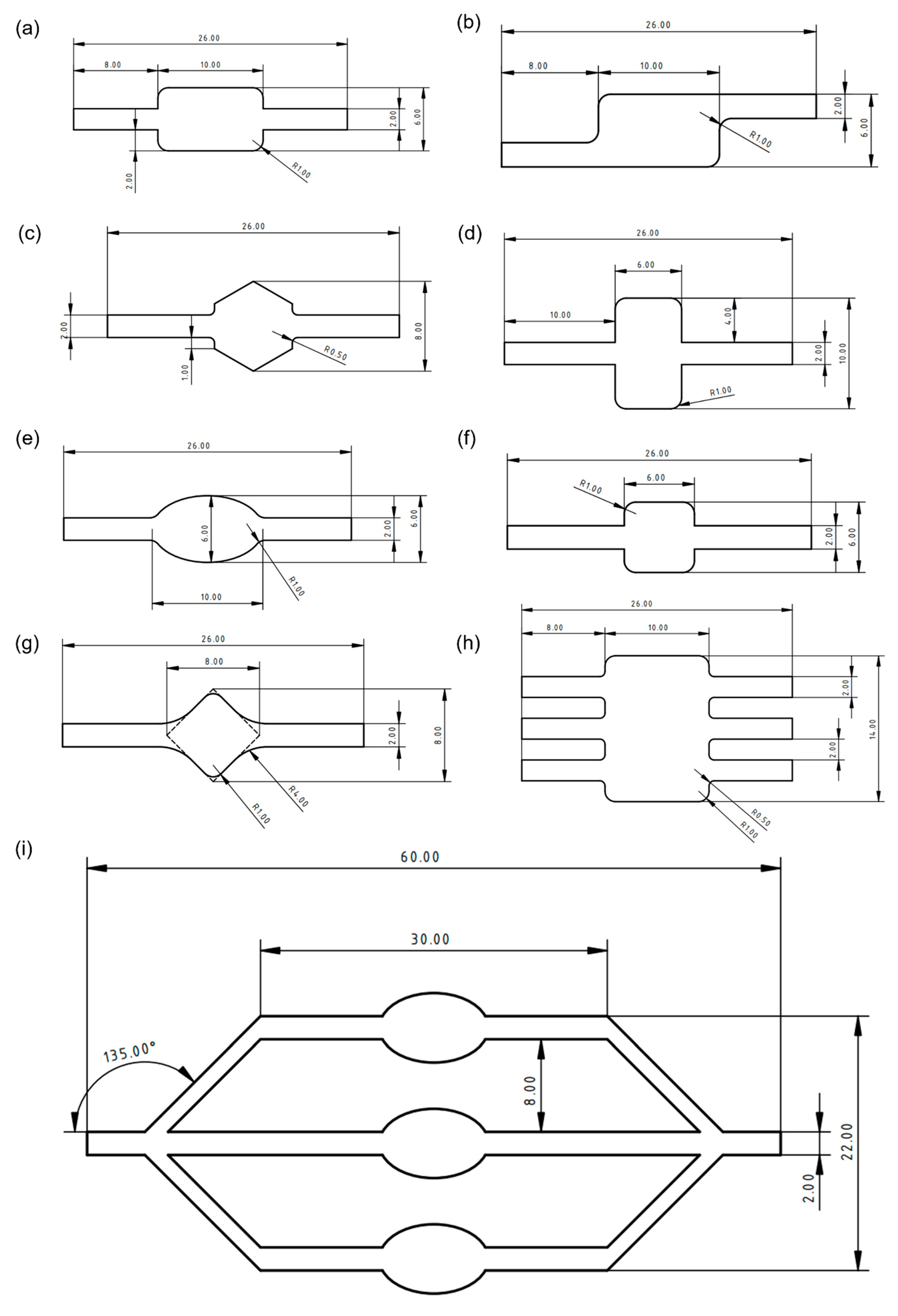
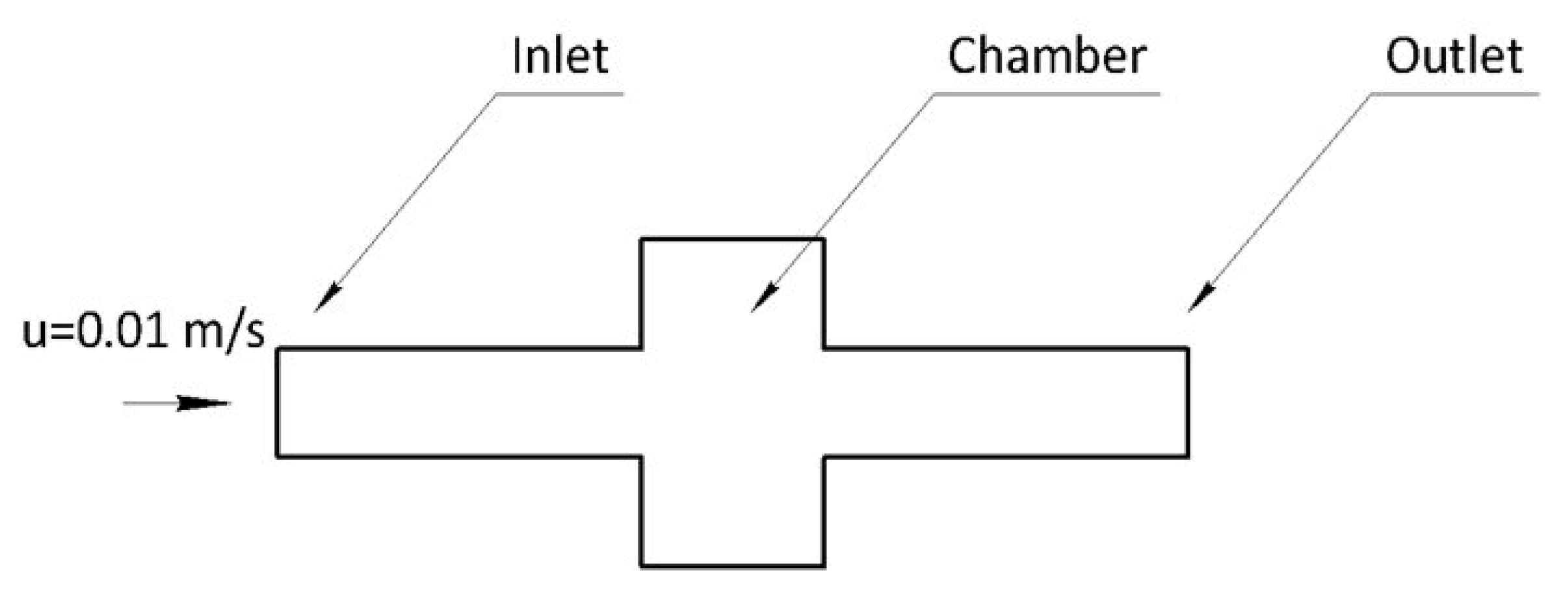
In order to conduct the analysis, the microfluidic structure should provide a uniform fluid flow. One way of achieving this is changing the internal geometry of a microfluidic chamber. In this study, several computational simulations in COMSOL Multiphysics were conducted to assess how different chamber shapes influence the flow parameters. Based on the results, a number of recommendations regarding the microfluidics chamber design are proposed.
3. Results and Discussion
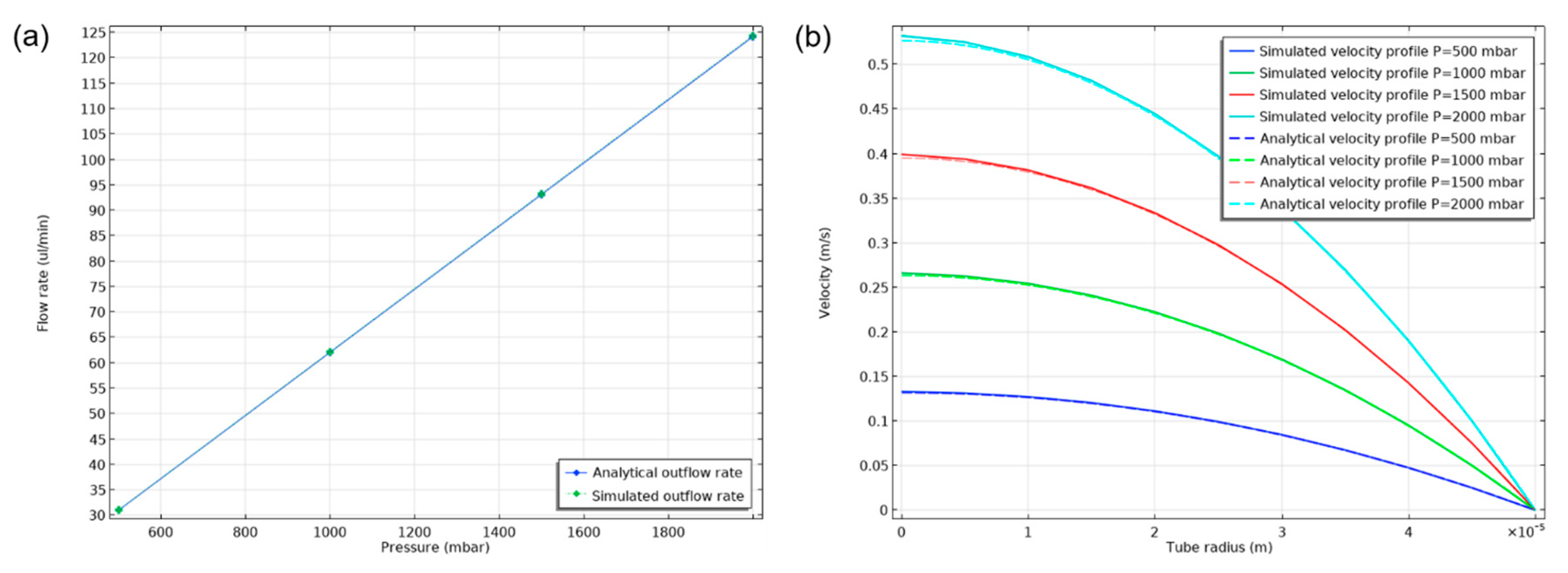
The laminar flow inside a circular pipe can be described analytically. The flow rate is linked to the pressure drop inside the pipe through the following equation:
where Q is the fluid flow rate, Δp is the pressure drop between inlet and outlet of the channel, R is the channel radius, η is the fluid dynamic viscosity and l is the channel length.
The radial velocity distribution of the fully developed flow inside the cylindrical channel is described as:
where
is the radial distance from the axis.
In order to validate the results of the selected mathematical model, a two-dimensional axisymmetric case of a 235 mm long and 100 um diameter cylindrical channel was simulated and compared with the analytical results of Equations (1) and (2). Inlet, outlet and wall boundary conditions were used in the domain boundaries. A fully developed flow was imposed at the inlet where different static pressure values were fixed from 500 mbar to 2000 mbar with a step of 500 mbar. Results from the parametric simulation are presented in
Figure 3. An excellent agreement between the computed and analytical flow rate–static pressure relation (Equation (1)) and of the velocity profiles (Equation (2)). The velocity profiles show a tendency to overestimate the analytical values near the axis of the channel and the difference is greater as the pressure drop increases. These results validate the accuracy of the selected computational model in this range of laminar flow conditions inside microchannels.
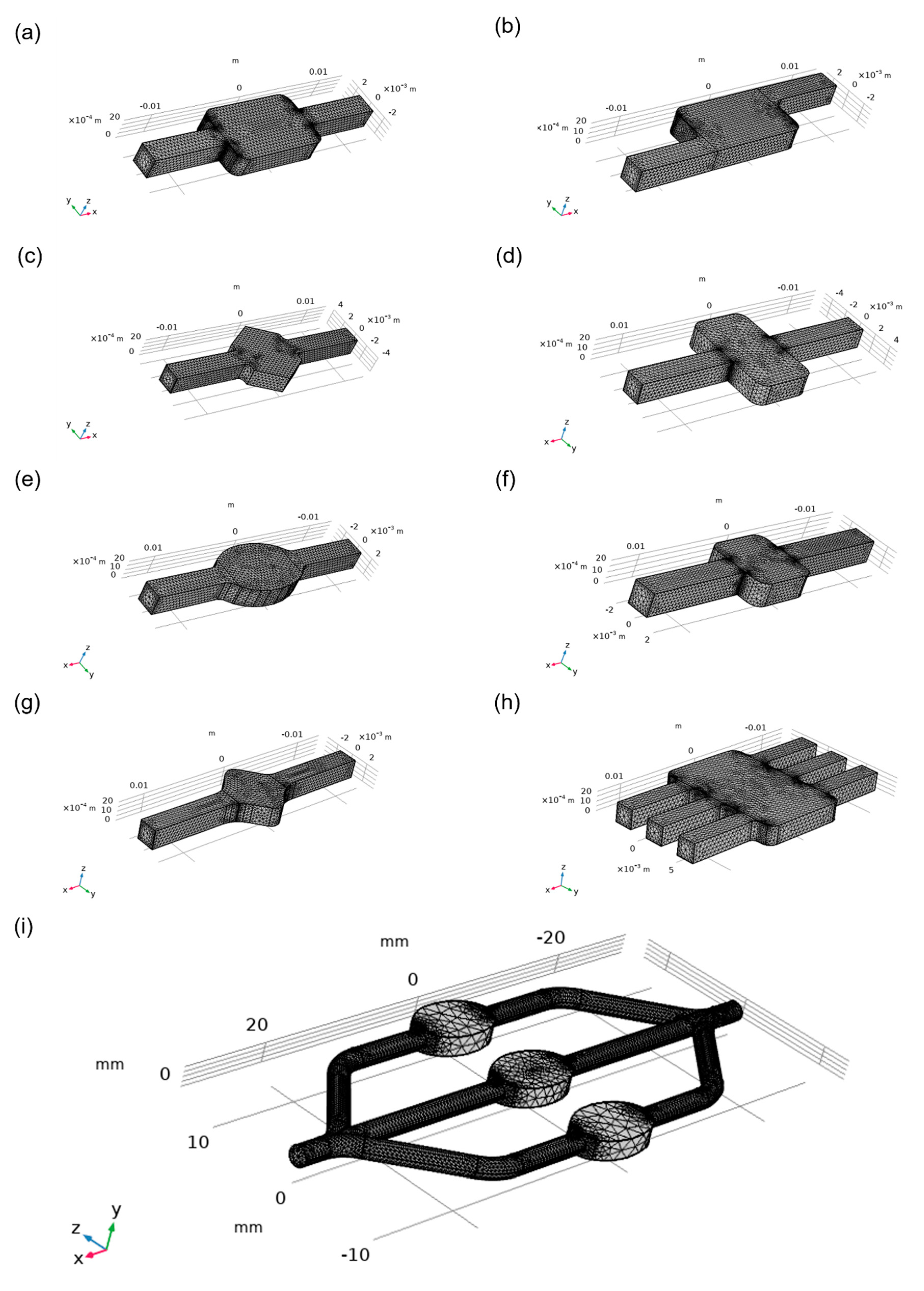
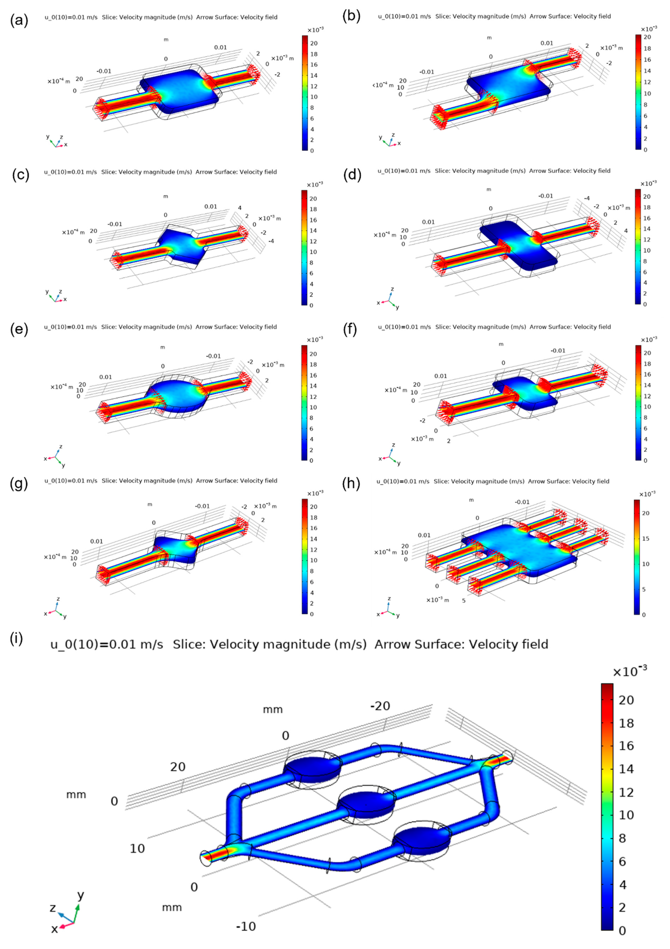
One of the most important characteristics of the microfluidic chamber is its ability to maintain a homogenous flow. Meshes that were used for simulations were generated by COMSOL automatically and are shown in
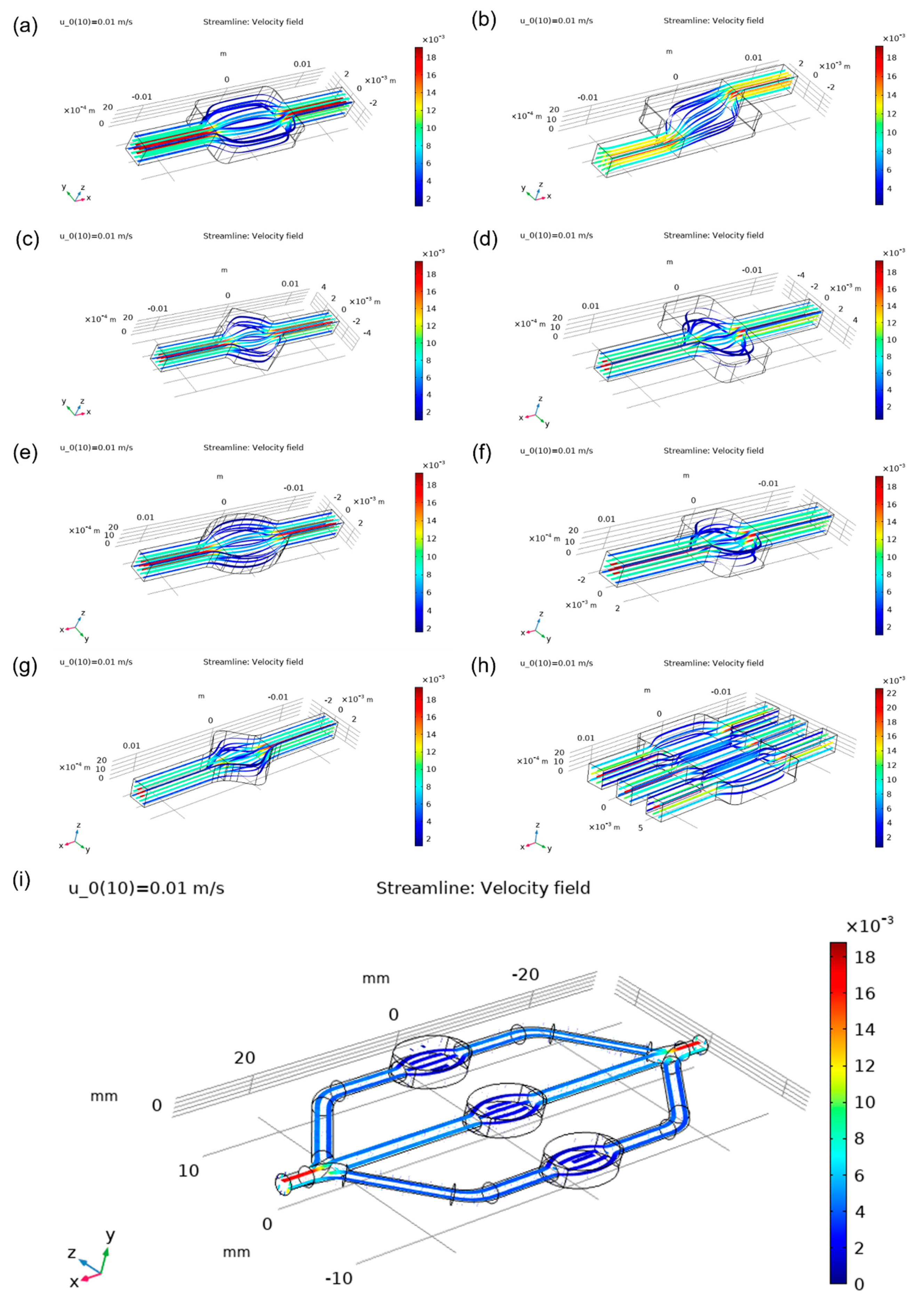
Figure 4. Designs were compared based on velocity magnitude inside the chamber,
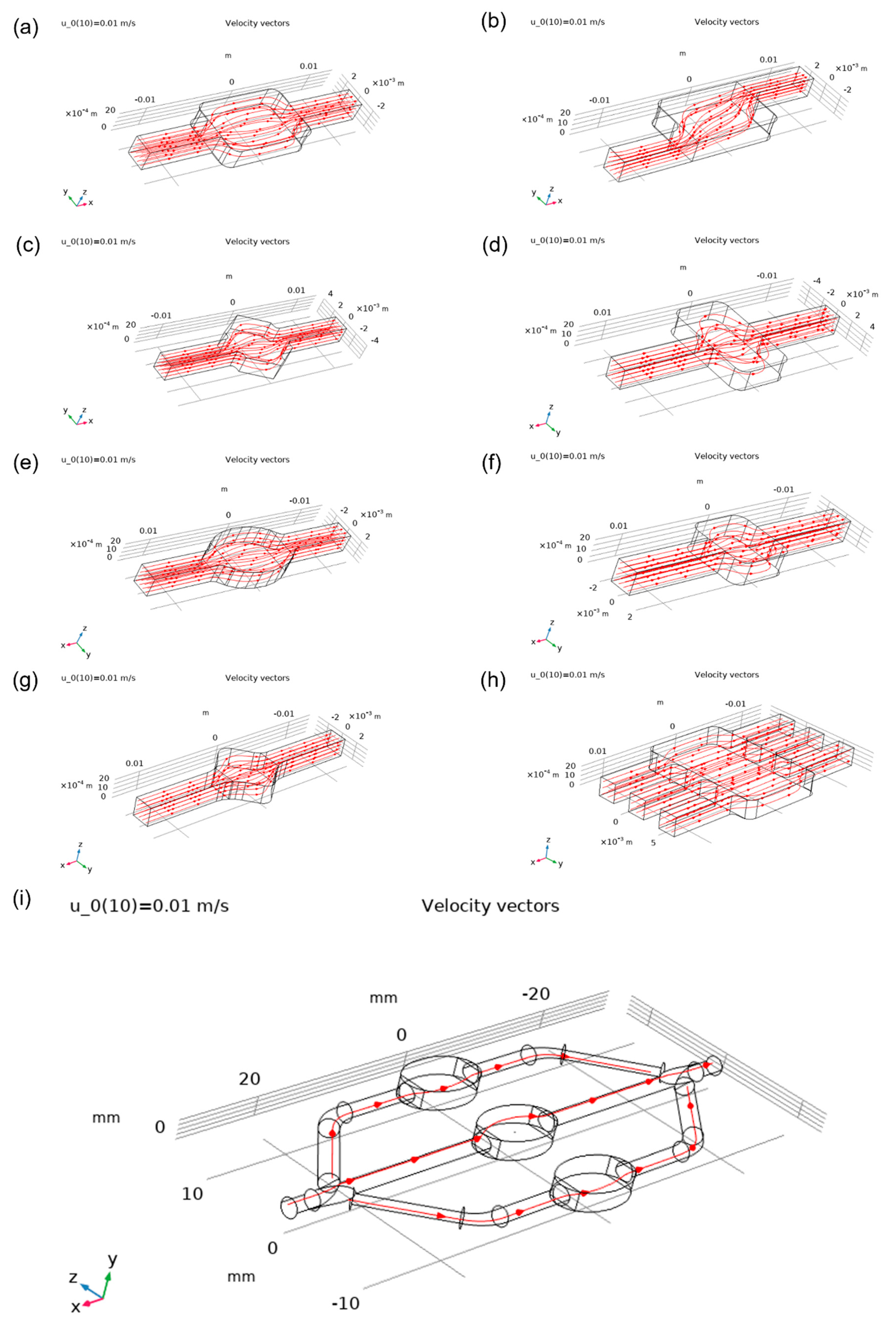
Figure 5. More cyan colouring of the chamber means a more even distribution of the analyte. Square and wide rectangular chambers showed large difference between the middle of the chamber and its side walls, thus making them less effective than other designs. The oval-shaped chamber presented one of the most homogenous flows, while the commonly used rectangular chamber showed good results but had some flow homogeneity around sharp corners. Asymmetric designs had a good behaviour which could be enhanced by optimising the design of the corners. The angled square resulted in a worse distribution than the hexagonal chamber design, while the latter showed relatively even distribution. The design with three inlets and outlets had one of the best distributions overall. The focus flow chamber design appeared to have a better distribution at the central chamber, while side chambers had a little less homogenous flow. Streamlines of the analyte as it moves inside the chambers can be visualised in
Figure 6, and velocity vectors are presented in
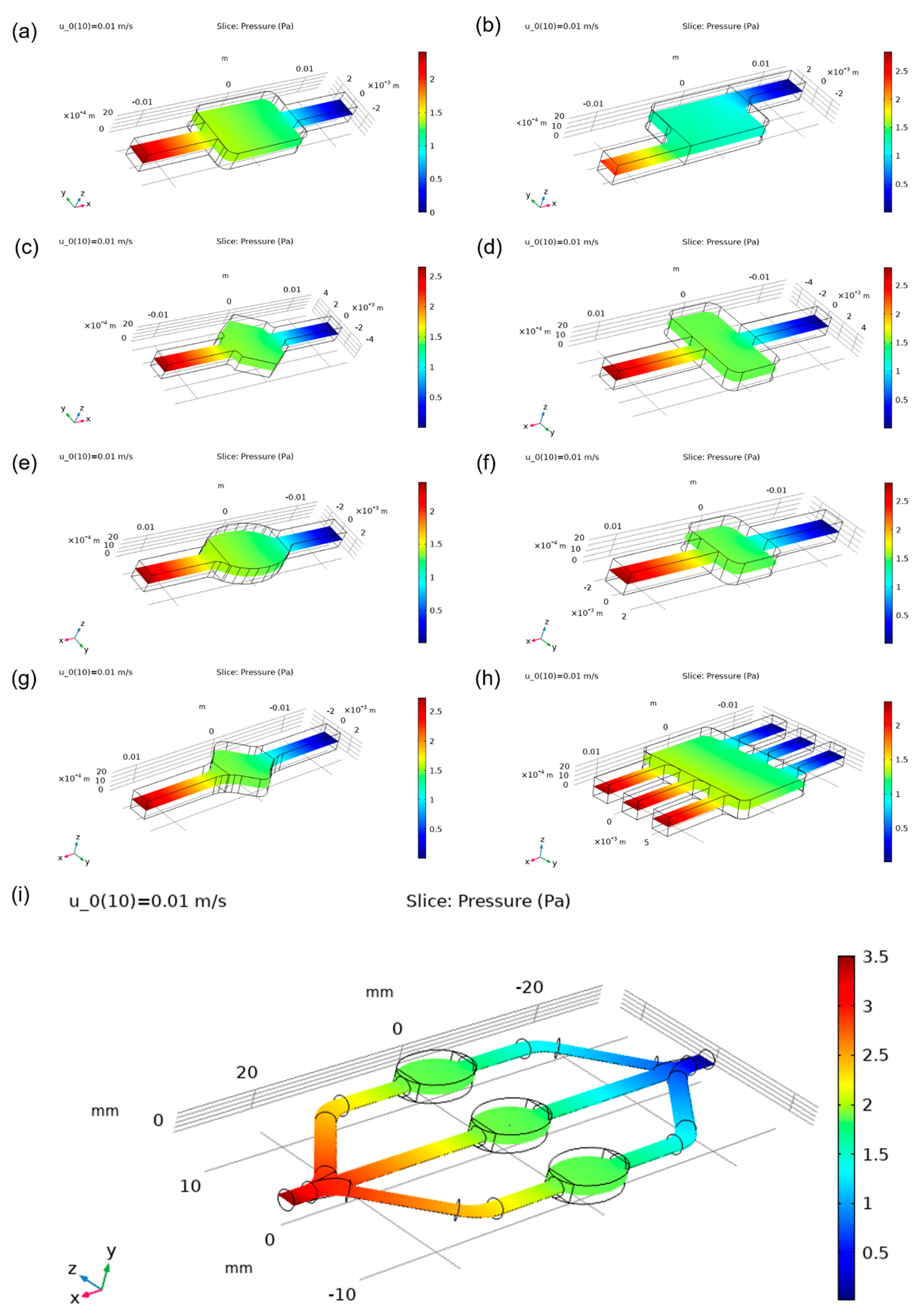
Figure 7. In addition, static pressure variation plots are presented in
Figure 8 and show an even distribution of static pressure inside all chambers aside from the asymmetric one. Interestingly enough, it has a slightly lower relative value of pressure inside its chamber than other designs.
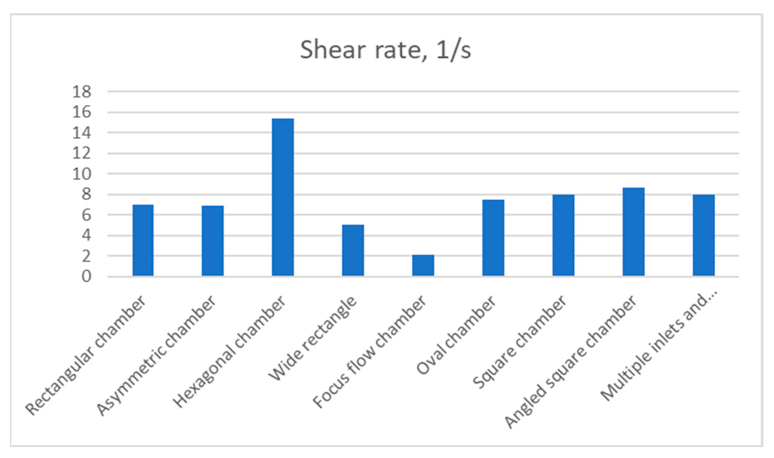
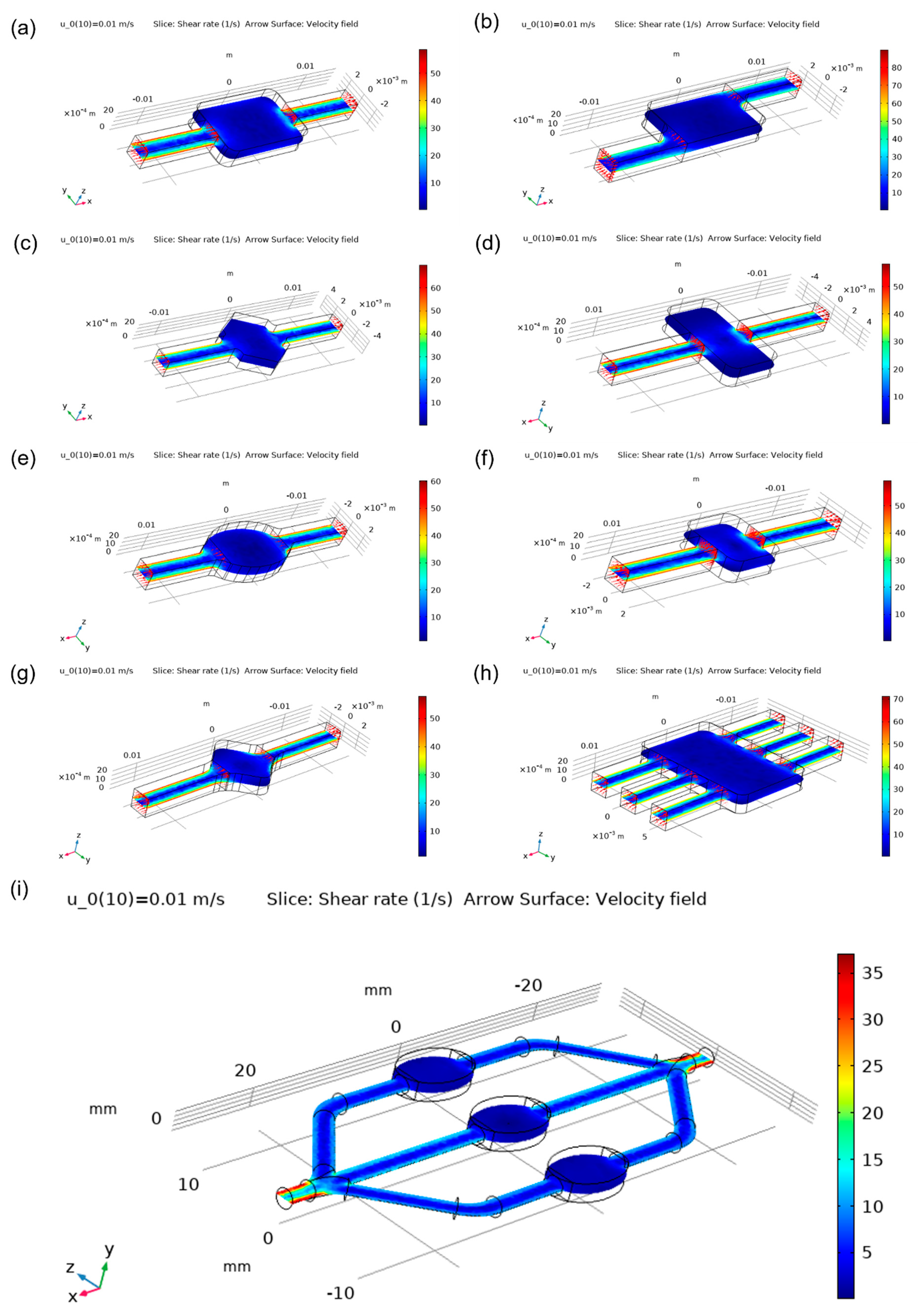
A useful flow quantity which can be used to assess the tendency of deformation that can be caused to the analyte molecules, is the shear rate which is calculated from the velocity gradients that are present inside the chamber. The shear rate distribution is presented in
Figure 9 and shows that the asymmetric chamber, the oval chamber and its focus flow derivative are a good selection for moving the analyte though the microfluidic system without significant angular deformation effects. The hexagonal chamber, on the other hand, seems to have a distribution of high shear rate inside its domain.
In order to quantitively assess each design, the following parameters were compared in
Table 1:
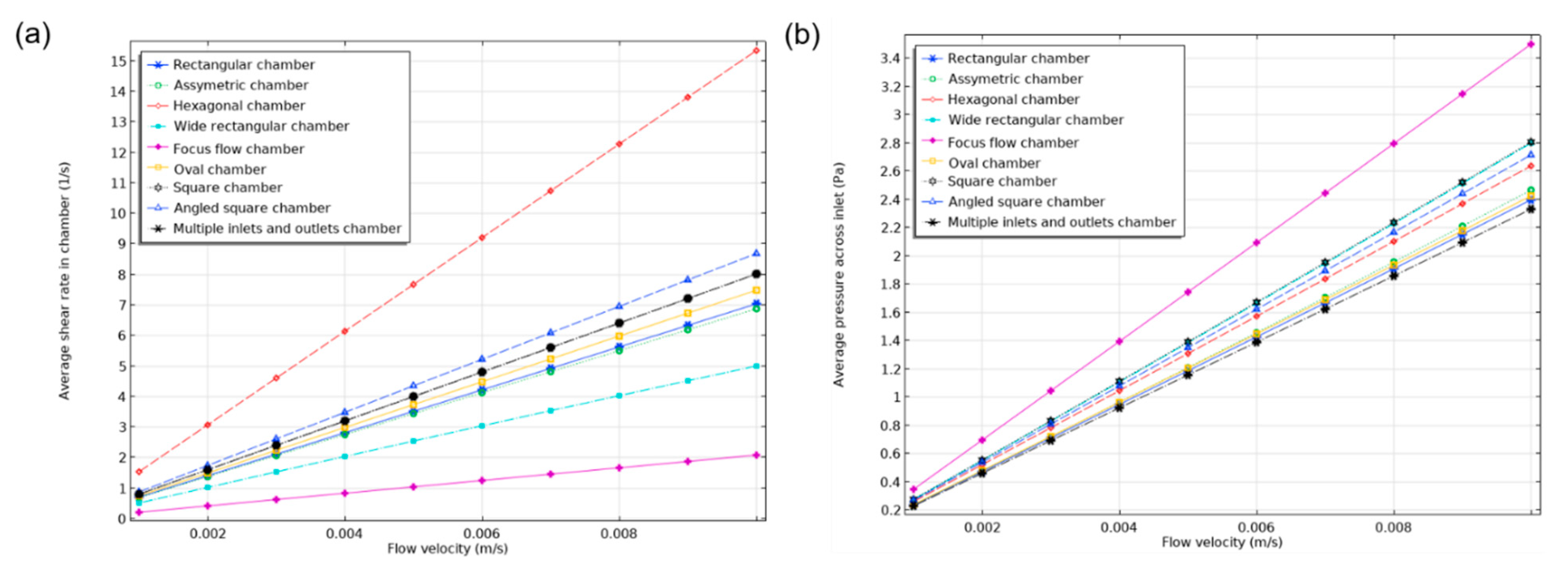
The hexagonal chamber demonstrated the highest value of shear rate (15.349 1/s) in relation to other designs,
Figure 10. Consequently, the design with multiple inlets and outlets demonstrated an average value of shear that was similar to square and oval chambers and was slightly worse than the angled square chamber. The focus flow chamber design was the least favourable choice in terms of shear rate value. Surprisingly, the rectangular chamber and its asymmetric design were almost equivalent, with shear rates of 7.0423 1/s and 6.8807 1/s, respectively.
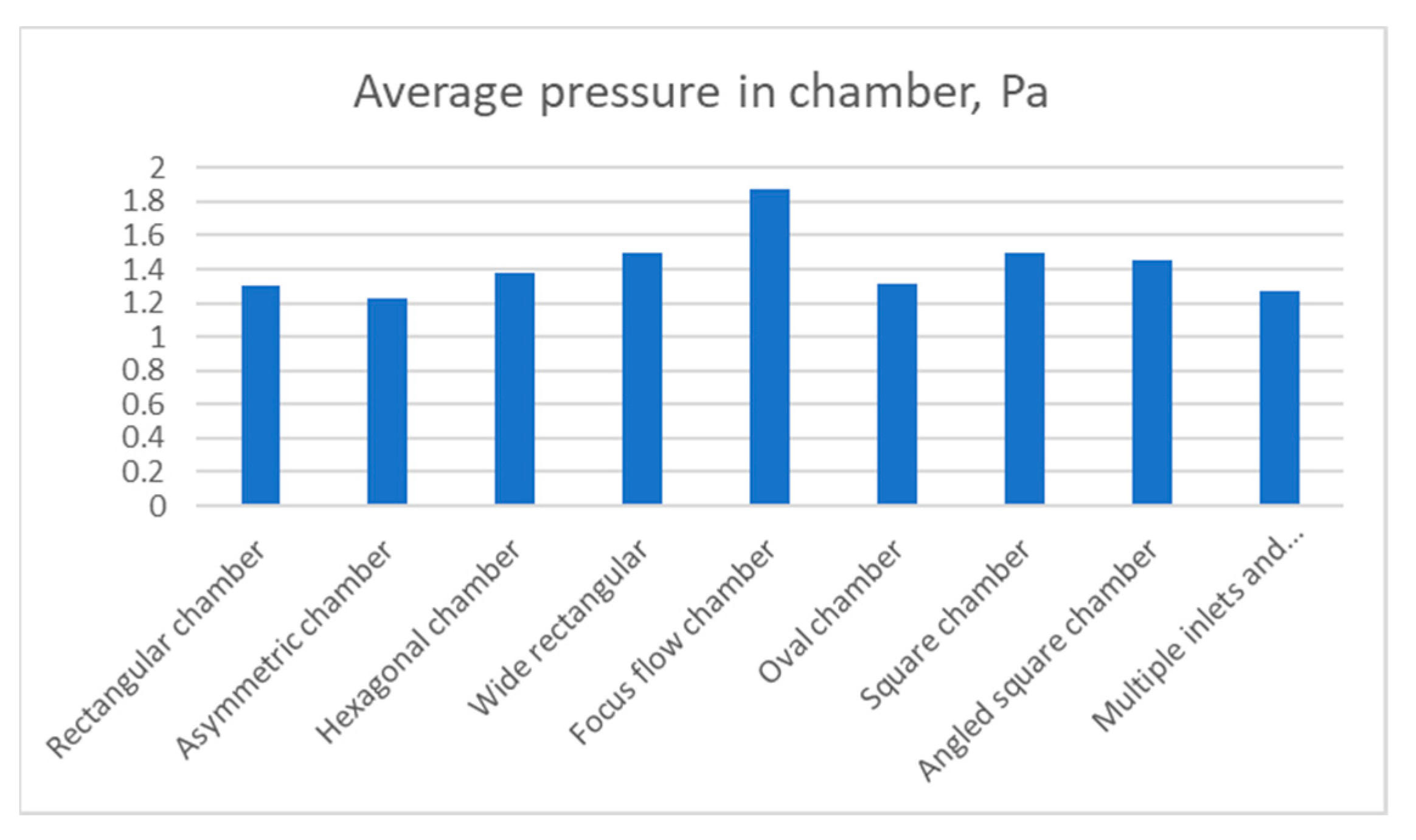
Due to the relatively large dimensions of the focus flow chamber design, an increased average pressure was present across all its chambers,
Figure 11. On the other hand, other designs showed similar results. Approximately 1.5 Pa was registered in the square, angled square and wide chambers. Oval and rectangular chambers showed almost identical results of 1.3 Pa while the lowest result was attributed to asymmetric chamber. The hexagonal chamber had the lowest pressure from all other designs.
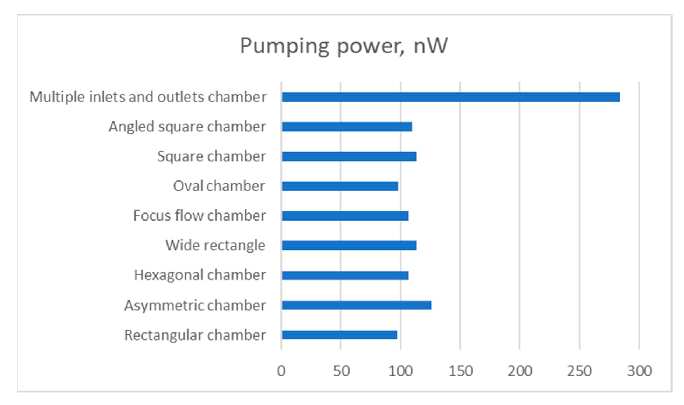
Lastly, the mechanical power that is required by a mechanical pump in order to sustain the specified flow rate, is compared in
Figure 12. The power, N, is calculated by the following relation:
From the results, it can be observed that the multiple inlets and outlets design consumed much more power than other designs. In fact, it consumed slightly less power than the three rectangular chambers. The second power demanding design is the asymmetric chamber at 125.58 nW. Again, the wide, square and angled square chambers show similar characteristics. The rectangular chamber requires approximately 1 nW less power than the oval chamber. Surprisingly, the focus flow chamber design required the least amount of power (82.63 nW).
In order to determine the effect of inlet flow rate on the shear rate and the pressure drop, a parametric study was undertaken by changing the inlet flow velocity. The inlet velocity changed from 0.001 m/s to 0.01 m/s with a step of 0.001 m/s. As can be deduced from the results in
Figure 13, both the shear rate and pressure drop changed linearly for all the studied designs as is anticipated in this type of laminar flows.
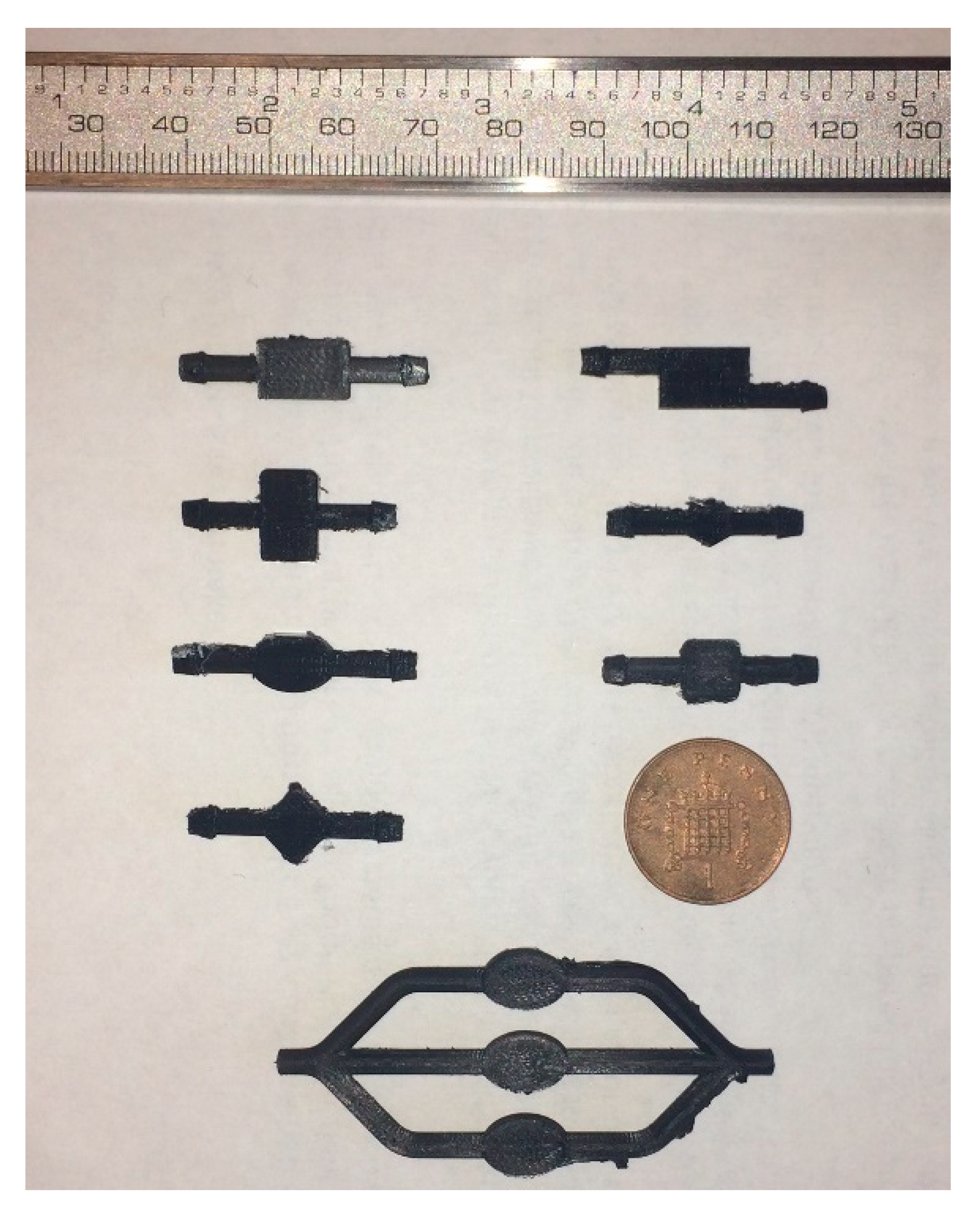
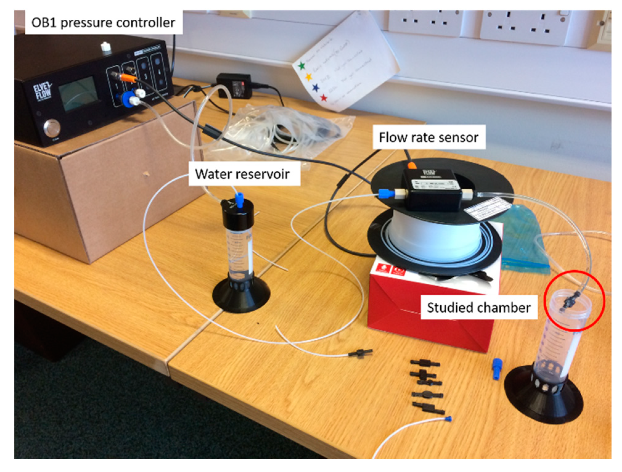
The chambers that were designed and simulated chambers were 3D printed using Ultimaker S5 and black PLA material,
Figure 14. These designs are intended to be assessed in conjunction with an Elveflow Microfluidics kit which consists of an 8 bar Jun-Air air compressor, OB1 flow controller, water reservoir, flow-rate sensor and tubing, as shown in
Figure 15.


