Abstract
Three-dimensional knitted helical coils are very sensitive inductive sensors that can be used to monitor breathing. Their inductance is high and the quality factor relatively low. A read-out circuit is designed and tested to track the inductance variations during circumference changes of a phantom chest. The challenge of the low-quality factors of the coil is resolved by designing a double cross-coupled FET pair with low capacitance. A digital counter records the frequency. A microprocessor samples the signal every 250 ms to minimize power consumption.
1. Introduction
Inductive sensors can be used in a variety of environments, one of which is non-contact body sensing networks. Application areas include respiration monitoring [1], ambulatory monitoring [2] and wireless power transfer [3]. Sensors require not only appropriate sensing characteristics but also readout electronics to transform the signal into practical data for further processing. In addition, the electronics need to run on batteries for long periods of time. In this work, we propose a low-power readout circuit for a 3D knitted helical coil. The coils have a high sensitivity up to ~68 nH/mm circumference change, a high rest inductance ~40 μH and a high resistance ~20 Ω, depending on knit implementation. The high resistance makes the quality factor Q of the coil relatively low. We present a high-Q low-power oscillator solution that gives a fast and stable response. A frequency counter converts the analogue signal into digital, and a microcontroller controls the sampling rate. This implementation reads breathing signals with good accuracy and at low power levels.
2. Materials and Methods
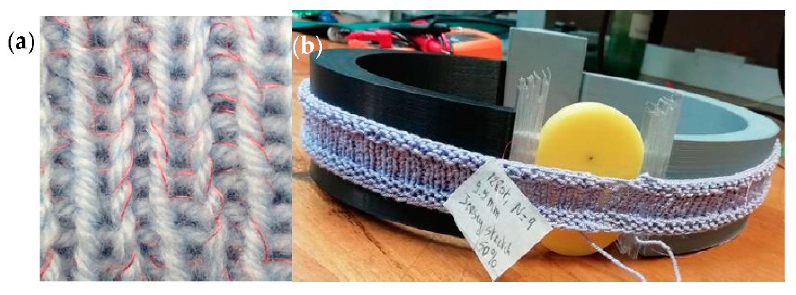
Figure 1 illustrates the knitted inductive sensor. This is created by knitting thin insulated metal wire and ordinary yarn simultaneously. A circular knit must be implemented to form a helical coil [4]. Figure 1a is a picture of the knit stitches with grey 3 mm yarn and red Cu insulated wire (~250 μm diameter). Figure 1b is a sample coil on a small chest phantom with moving “ribs”. For dynamic measurements, the yellow disk is rotated. The speed and angle of the rotation is controlled by a computer. Plastic slides are inserted next to the oval disk for static measurements.
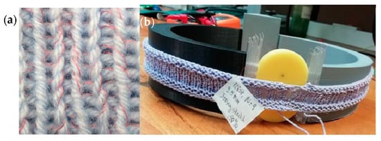
Figure 1.
(a) Thin insulated metal wire integrated in the knit stitches that form the 3D helical coil. (b) The chest phantom holding a test coil. The oval disk is connected to a small motor to rotate it around its axis over programmed angles and with a given speed.
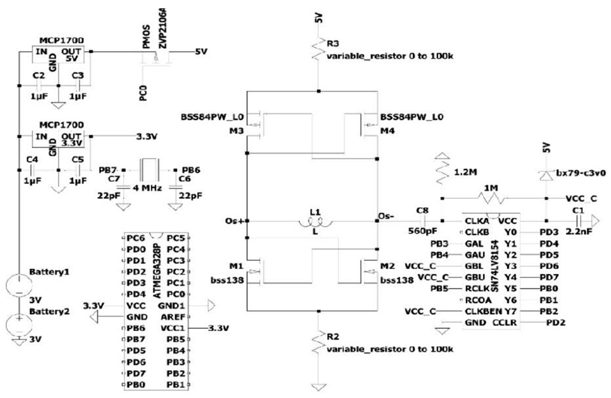
The circuit diagram of the readout is given in Figure 2. All components are defined on the diagram. The oscillator is formed by two cross-coupled FET pairs [5]. The top pair use pMOS to supply power to the bottom pair. The bottom nMOS pair form a negative resistance. The variable inductor represents the coil. No further components are added as the capacitance of the FETs forms the LC oscillator with the coil’s inductance. The capacitance of the cross-coupled pair is ~41pF, depending on the chosen bias point of the FETs. FETs should remain in their linear region to limit harmonics. Low C FETs boost the quality factor of the oscillator , with R as the internal coil resistance, L as its inductance and C as the FETs’ capacitance. The power supply to the oscillator is stabilized using a low-power 5 V voltage regulator. This ensures that the variation of the battery voltage upon use is minimized and does not interfere with the oscillation frequency.

Figure 2.
Circuit diagram. All components are identified.
In this implementation, two variable resistors were used. The top one controls current flow and thus amplitude of the oscillations. The bottom resistor controls the DC offset from the ground. The input signal for a logical one of the counters must be higher than 0.7 × Vcc and lower than 0.3 × Vcc for a logical zero. Thus, the resistor values are chosen so as to ensure correct operation of the counter and to minimize its current consumption. These settings are linked to the specific coil used and can be fixed once the coil type is fixed. Since the counter and microcontroller are power-hungry, their supply is minimized to ~3 V. A pMOS switch (Q1 in Figure 2), controlled by the microcontroller, switches the circuit on and off. The system is on for ~45 ms and in sleep mode for ~250 ms. The frequency is counted for 10 ms and output recorded by the microcontroller. The oscillator response time is less than 10 μs; however, the counter takes longer and a ~5 ms delay in recording the output is implemented. To further reduce power, the microprocessor runs on an external clock of 4 MHz. This implementation allows the circuit to run on the same batteries for multiple days.
3. Results
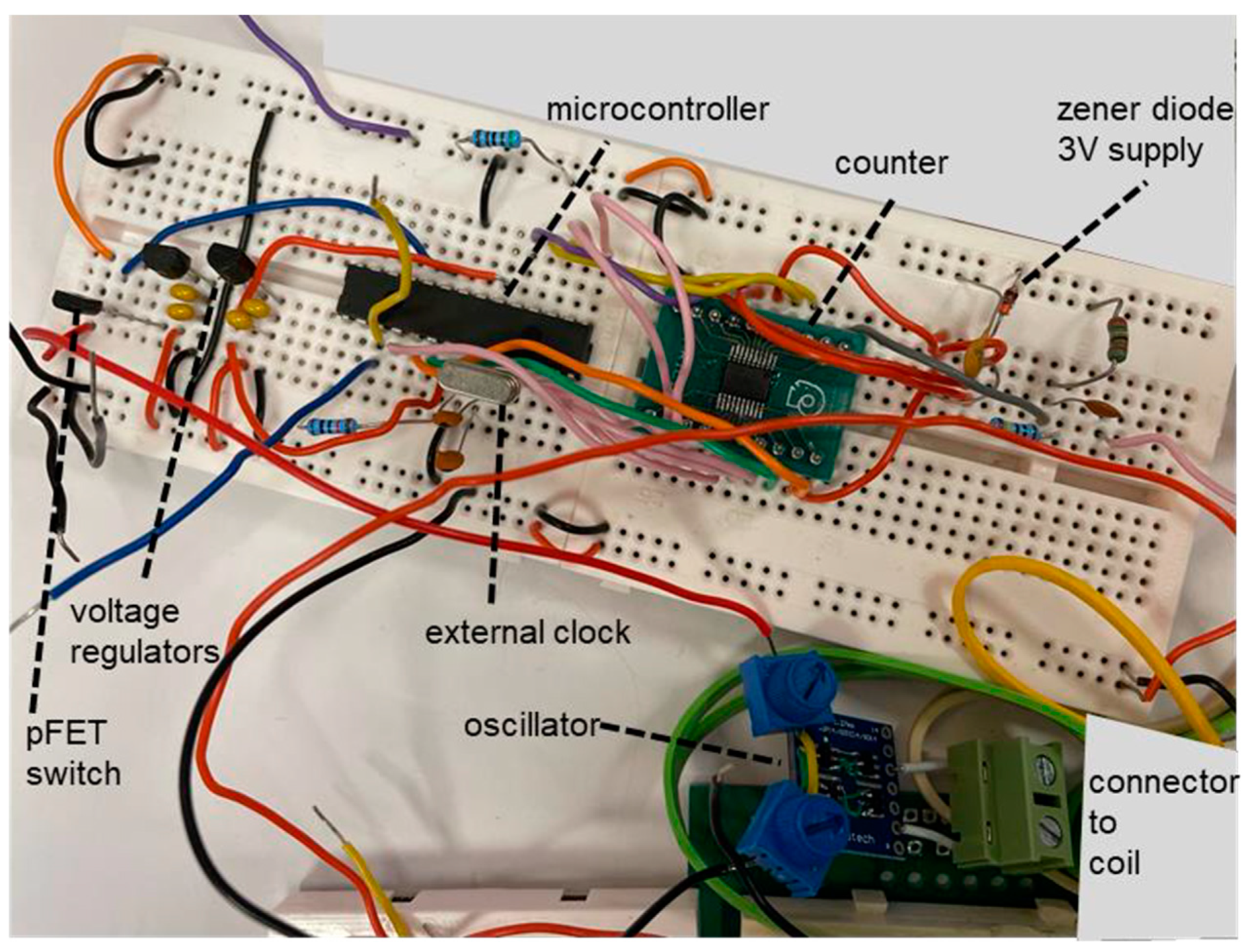
For testing, the circuit was implemented on a breadboard (Figure 3), with the oscillator and counter implemented on a PCB. Realizing the full circuit on a PCB with surface mount components and a microcontroller with integrated counter and watchdog timer will make the implementation more compact and wearable.
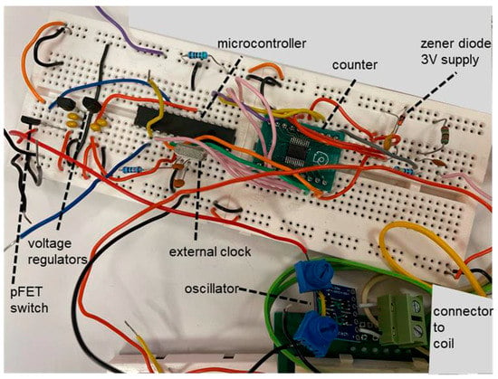
Figure 3.
The circuit of Figure 3 implemented on a breadboard.
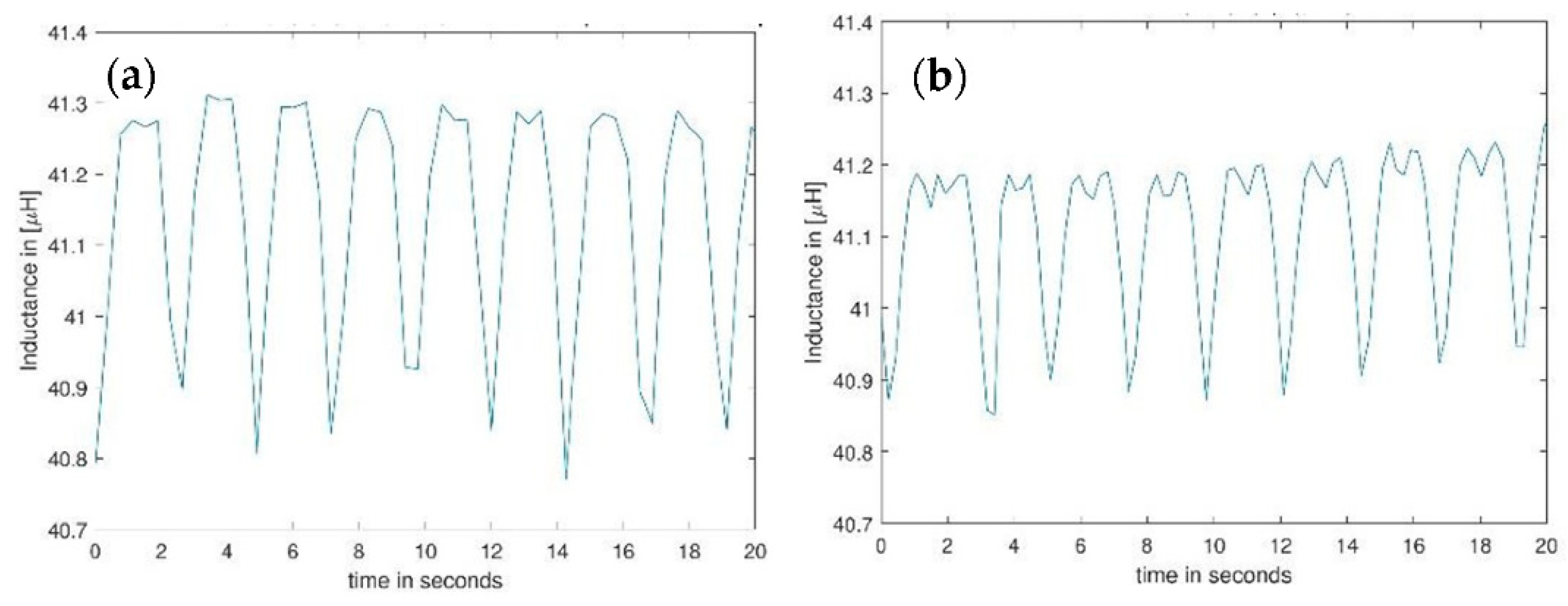
The performance of the circuit was tested using the dynamic setting of the phantom chest and rotating the disk over ~60° at a speed of ~2.4 turns/s. To analyse whether the circuit gives a true representation of the “breathing” signal, the measured oscillation frequency was converted into an inductance using C = 40.8 pF. This measurement can then be easily compared to the measurement of the same breathing setup with a Wayne–Kerr 6500B precision component analyser. Figure 4a shows the inductance changes using the circuit and Figure 4b that of the precision component analyser. The measured variations are similar, but the details of the geometrical profile changes in the disk (see the higher inductance values) are less well-represented. This is because of the lower sampling rate of the circuit compared to the Wayne–Kerr. Increasing the sampling rate is possible but will consume more power and reduce battery life. Overall, our low-power implementation gives a fair representation of the simulated breathing signal.

Figure 4.
Result of a dynamic measurement using the phantom chest (a) using the readout circuit given in Figure 3 and converting the frequency back to inductance changes and (b) using the precision impedance amplifier (Wayne–Kerr).
Different coils were knitted in a 1/1 rib stitch using cotton yarn with a different number of rows that include the metal wire. The number of knitted rows with the wire is equivalent to the number of windings (turns) in a coil. All coils had the same diameter. Increasing the number of turns, N increases the self-inductance of the coil but also increases its resistance. The oscillation frequency decreases with the increasing number of turns. This translates into a decrease in power consumption with the increasing N. Figure 5a gives the power consumed by the oscillator and counter during the time it is on but ignores the power consumed by the microprocessor that remains the same for all implementations. Figure 5b gives the sensitivity: Δf/Δl with l circumference. This demonstrates a trade-off between power and sensitivity. This trade-off is a consequence of converting inductance to frequency that causes a decrease in sensitivity for an increase in rest inductance value. For the given coil implementation, a compromise would be to use N = 5, that has a higher power consumption but also higher sensitivity.
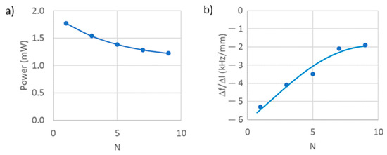
Figure 5.
(a) Power consumed by the circuit (excluding the microprocessor) as a function of the number of turns N. (b) The variation in the frequency as a function of variation of circumference l. The knit is a 1/1 rib knit in cotton. The chest phantom of Figure 2 is used for static measurements using the thin plastic sliders to increase circumference.
To decrease power consumption, the total length of the metal wire integrated in the knit can be reduced by reducing the number of stitches in which the metal is integrated. This needs to be done carefully so as not to jeopardize the flexibility in the knit. To increase sensitivity, a jersey rather than a rib stitch can be used, as a jersey stitch gives a lower inductance value for the same number of turns. In addition, it was found that the yarn crossover points between the stitches in jersey knit increase the inductance variation as a function of stretch compared to that using rib stitch. A more tight-fitting garment obtained by reducing needle size will also boost performance as it not only decreases the metal wire length but also follows chest movements better [6].
In conclusion, the design of a high-Q oscillator using low-capacitance FETs in a double cross-coupled pair configuration allows the readout of breathing signals sensed with 3D knitted helical coils that have a high sensitivity in inductance variation with circumference but also a high resistance. This supports the implementation of fully wearable knitted breathing sensors.
Author Contributions
Conceptualization, K.F. and W.F.; methodology, K.F. and K.K.; validation, K.K., A.A. and K.F.; formal analysis, K.K., A.A. and K.F.; investigation, K.K. and A.A.; resources, K.F.; data curation, K.F.; writing—original draft preparation, K.F.; writing—review and editing, K.K., A.A. and K.F.; visualization, K.F.; supervision, K.F.; project administration, K.F. All authors have read and agreed to the published version of the manuscript.
Funding
This research received no external funding.
Institutional Review Board Statement
Not applicable.
Informed Consent Statement
Not applicable.
Data Availability Statement
From K.F. upon request.
Acknowledgments
We thank V. Body and A. Halimi for help in the lab.
Conflicts of Interest
The authors declare no conflict of interest.
References
- Fobelets, K. Knitted coils as breathing sensors. Sens. Actuators A Phys. 2020, 306, 111945. [Google Scholar] [CrossRef]
- Fobelets, K. Ambulatory Monitoring Using Knitted 3D Helical Coils. In Proceedings of the 3rd International Conference on the Challenges, Opportunities, Innovations and Applications in Electronic Textiles (E-Textiles 2021), Manchester, UK, 3–4 November 2021. [Google Scholar]
- Fobelets, K.; Sareen, K. Thielemans K, Magnetic coupling with 3D knitted helical coils. Sens. Actuators A Phys. 2021, 332, 113213. [Google Scholar] [CrossRef]
- Fobelets, K.; Thielemans, K.; Mathivanan, A.; Papavassiliou, C. Characterisation of knitted coils for e-textiles. IEEE Sens. J. 2019, 19, 7835–7840. [Google Scholar] [CrossRef] [Green Version]
- Ebrahimzadeh, M. Design of an ultra-low power low phase noise CMOS LC oscillator. Int. J. Soft Comput. Eng. (IJSCE) 2011, 1, 78–81. [Google Scholar]
- Kiener, K.; Anand, A.; Fobelets, W.; Fobelets, K. Low Power Respiration Monitoring using Wearable 3D knitted Helical Coils. IEEE Sens. J. 2022, 22, 1374–1381. [Google Scholar] [CrossRef]

Publisher’s Note: MDPI stays neutral with regard to jurisdictional claims in published maps and institutional affiliations. |
© 2022 by the authors. Licensee MDPI, Basel, Switzerland. This article is an open access article distributed under the terms and conditions of the Creative Commons Attribution (CC BY) license (https://creativecommons.org/licenses/by/4.0/).