1. Introduction
Combined cycle gas turbines (CCGTs) are widely used because they can reach a higher efficiency by producing a great amount of electrical power with low carbon dioxide emissions, compared with conventional plants [
1,
2]. Nowadays, there is an increasing interest in combined cycle gas turbines, especially in countries endowed with huge natural gas resources [
3].
Operating power systems have become more complex than traditional systems, due to the great interconnection and presence of new technical equipment. Thus, in a generation power plant, there is more than one generating unit providing power into the system. Generator speed is significant for power generation plant performance, as it is widely dependent on the performance of the fuel system, the feed water, the combustion system, and the air flow system [
4]. For satisfactory operation of this system, the frequency should be kept practically constant.
Depending on the frequency deviation, the frequency control system provides local and automatic frequency control by adjusting the speed governor within a few seconds after a disturbance, in order to maintain the stability of the power system [
5]. The speed variation and frequency transient have a direct effect on the air flow and fuel flow supply, since the air compressor and the fuel system are both attached to the shaft of the unit (CIGRE, 2003) [
6,
7,
8]. Therefore, it is necessary to involve a suitable frequency control system, in such power plant.
This study is based on the dynamic model of a CCGT, proposed by Kakimoto and Baba (2003) [
5], which was inspired by Rowen (1983) [
9]. Our contribution focuses on the governing control system. The simulation model of the system was developed in MATLAB/Simulink, and the impact of the load variation and the damping change on the CCGT plant was examined.
2. Combined Cycle Process
In a CCGT, the gas turbine provides two-thirds of the total unit power output and the steam turbine provides the other third. Practically, the overall thermal efficiency of the power plant, in a combined cycle system, increases from 37% to 57–61% [
3,
8]. In a CCGT, air is compressed isentropically in the compressor before being fed into a combustion chamber, where fuel is added and burned. The energy of the expanding air is then converted into mechanical work in a turbine [
10]. The gases exhausted from the gas turbine are used to drive a steam turbine, by transmitting these gases through the heat recovery steam generator (HRSG). This process is the basis of a combined cycle gas turbine plant. The mechanical power produced by the steam turbine is converted into electrical power by the generator.
3. Mathematical Modeling of the Combined Cycle Gas Turbine
The thermodynamic process of the gas and steam turbine is modeled using algebraic equations (Spalding and Cole, 1973), consistent with adiabatic compression and expansion, as well as with the heat exchange in the HRSG [
6,
8]. It is assumed that the mixture of air and gas is almost equal to the air flow. The ratio of the input–output temperatures for the isentropic compression is given as follows [
6,
8]:
where
: The ratio of specific heat;
Pr: The actual compressor ratio (for nominal airflow (W = 1 pu), Pr = Pr0).
However, the compressor discharge temperature (
td) and the gas turbine exhaust temperature (
te) can be written, respectively, as:
where
ti: The ambient temperature;
tf: The gas turbine inlet temperature.
and are, respectively, the compressor and turbine efficiency.
The mechanical output power produced by the gas turbine is given by:
The mechanical output power produced by the steam turbine is given by:
In a steady state and for initialization purposes, the generation output power of the plant is given by:
The inlet temperature (
Tf) and exhaust temperature (
Te) (note that for normalized conditions
Tf =
Te = 1 (pu)) are:
4. Frequency Falls Effect on the CCGT
It is known that various power grid blackouts are caused by the imbalance in frequency control requirements [
7,
11]. The falling system frequency has several effects on the CCGT plant. One of them is expressed in the inertia response. This response, alongside with the load response, is important to the power system in damping the initial frequency fall [
3]. Another effect of droop frequency is a fall in the compressor speed, which leads to a drop in the pressure and a reduction in the airflow, which means an increase in fuel consumption and a rise in temperature [
7,
12]. At this time, the temperature controller will actually reduce the fuel demand; consequently, the output power of the gas turbine decreases.
5. Power System Frequency Control
Since the frequency network is proportional to the generator speed, frequency control may be achieved by regulating the rotor speed of the generator. This is assumed by the speed governing control system which is installed in order to adjust the output power and regulate the speed and the frequency deviation [
13]. Depending on the sign of the frequency deviation, the frequency control action is expected to start automatically and immediately provide power support by increasing or decreasing the active power output [
11].
5.1. Load Response to the Frequency Deviation
The generator speed variations lead to a change in the power output and incite a frequency imbalance [
4]. The dependency of the speed (frequency) on the load may be expressed as:
where
: load change;
: speed deviation;
: load damping constant.
The damping constant is expressed as a percent change in load for one percent change in frequency [
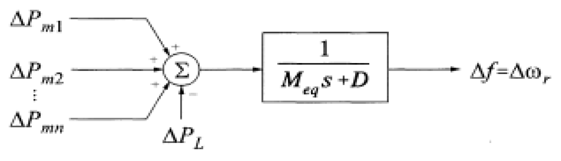
4]. When more than one generator is operating in parallel, the output power of each unit can only be varied by adjusting its load reference, which directly affects the speed variation. The loads are lumped into an equivalent single damping constant, ‘
D’, and the equivalent generator has an equivalent inertia constant of
Meq [
4]. The equivalent generator speed represents the frequency, and in per unit (pu), the two are equal (
) (
Figure 1).
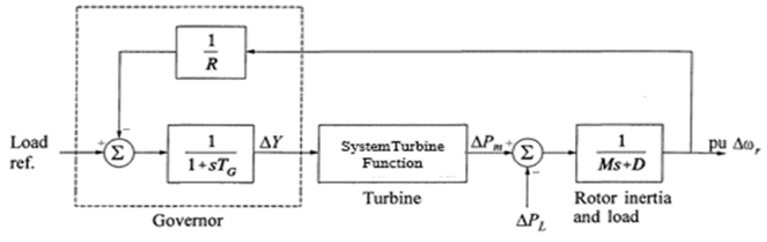
5.2. Turbine Governing Systems Response
It is assumed that the frequency is the same at all times and at all points in the network. Regardless of the location of the load change, all producing units for speed governance will contribute to the global change in generation [
4]. Therefore, we consider only a single inertia value, which gathers all the inertia of the individual units. This is done by summing the individual kinetic energies into a single generation kinetic energy value [
4]. The speed governing process developed by Kundur [
4], shown in
Figure 2 is applied in this study.
6. Simulation Model of CCGT
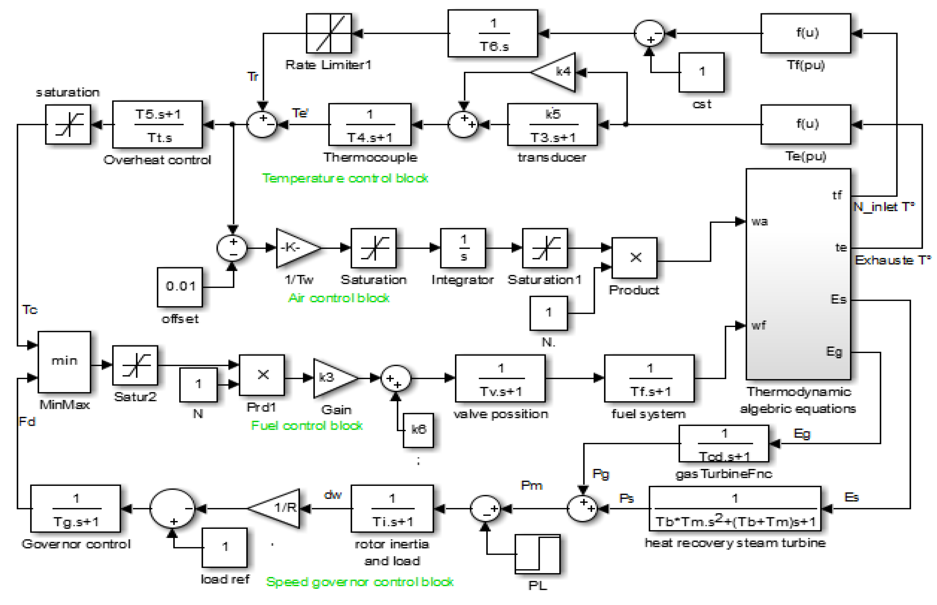
The dynamic model of the combined cycle gas turbine plant consists of power generation units and their control system. In this study, the combined cycle system is constituted by two turbines (gas turbine and steam turbine) and one generator unit. The model is based on the simplified transfer function of gas and steam turbines and eventually the control system, which is planned as follows:
The first loop consists of the speed governor (load frequency control), which is necessary for the stability of the system. It detects frequency anomalies and regulates the fuel request signal.
The fuel control is directly related to the rotor speed. The rotor speed and frequency have a direct influence on air and fuel consumption [
3].
The temperature control loop has a significant role in the operating system of the power plant, as it adjusts the fuel flow (
Wf) and airflow (
W) based on measurements of the exhaust temperature, by adjusting the fuel demand when the frequency falls and the output power decreases [
2].
The selection of the control loops (frequency or overheat) is achieved using the low-value-select (LVS) by switching the lower value (Tc or Fd).
7. Simulation Results and Discussion
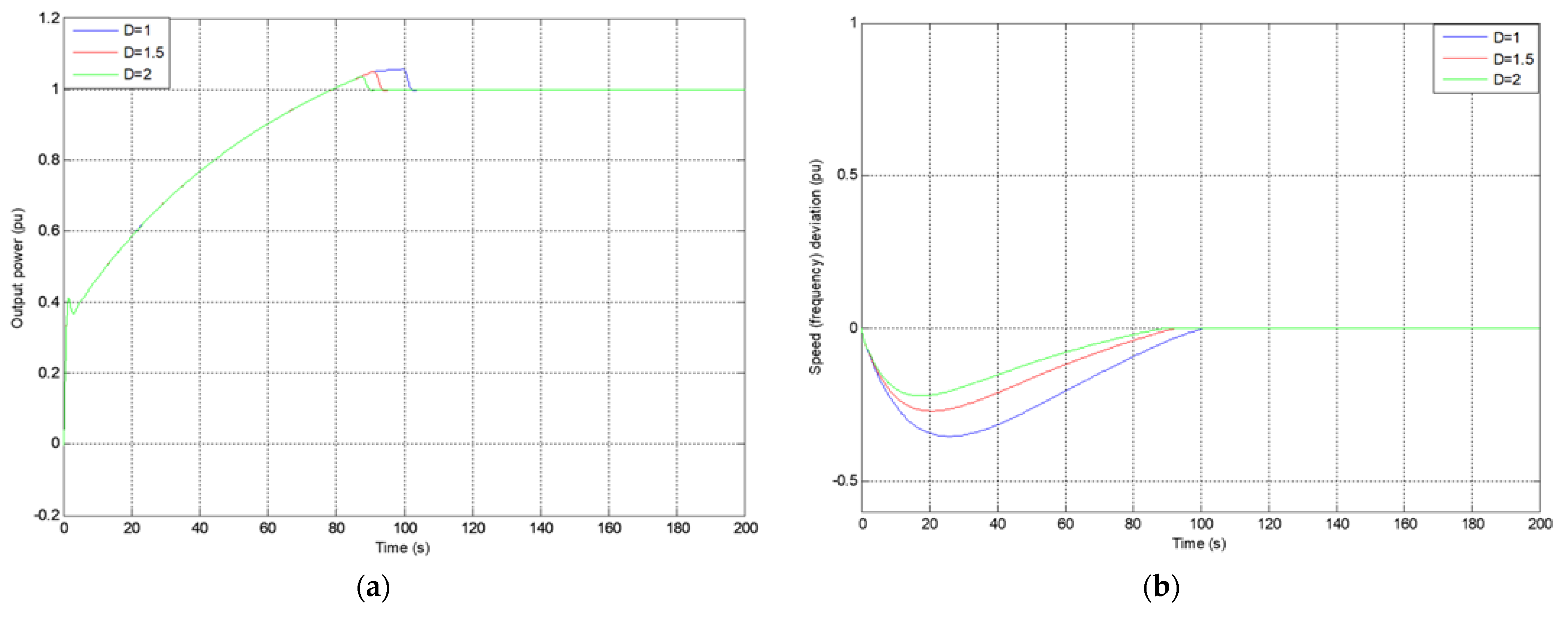
The effect of the damping constant on the system dynamic is shown in
Figure 4. In the transient state, it can be seen that the frequency drop decreases with the increase in damping constant “
D”. In the steady state, the output power and frequency remain at their nominal values. It is noted that a value of
D = 2 means that a 1% change in frequency would cause a 2% change in load [
4].
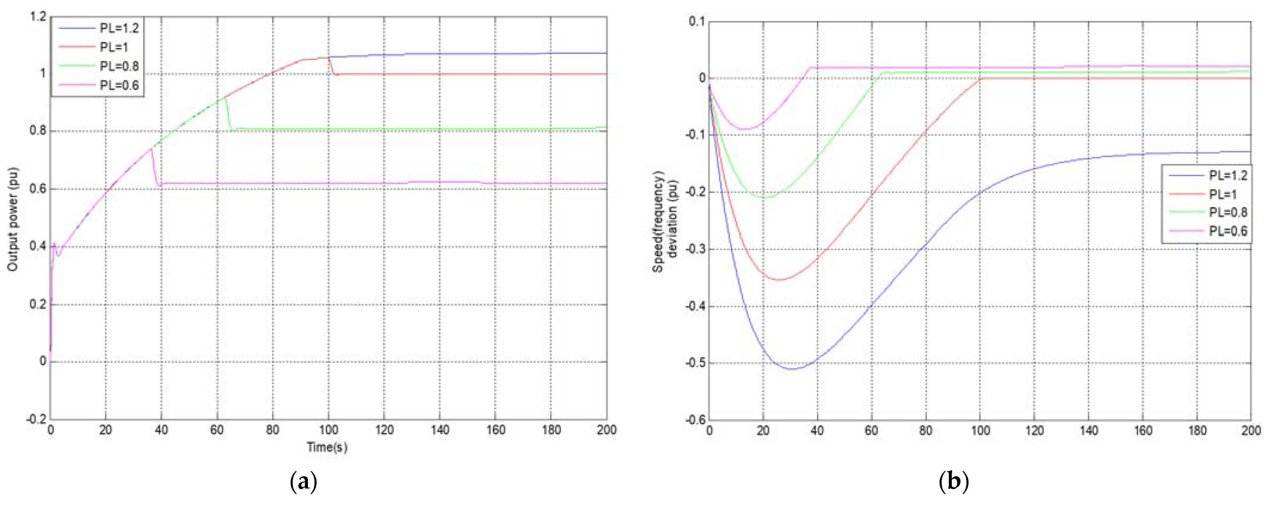
In
Figure 5, it can be seen that the output power and frequency deviation decrease as the load change is lower, which means that the system control adjusts the output power generation according to the load change. When the frequency deviation is slight (Δ
f = −0.09 Hz), the frequency takes less time to return to its nominal value compared to the case of an overload change, where the frequency drop is about Δ
f = −0.51 Hz. It can be noted that the steady state depends on this change. In this phase, for lower load changes, the output power is less than its nominal value and the frequency deviation is very slight, but in a positive sense (Δ
f = +0.005 to Δ
f = +0.01 Hz). For the overload change, the output power is greater than its nominal value and the frequency deviation still falls (Δ
f = −0.13 Hz).
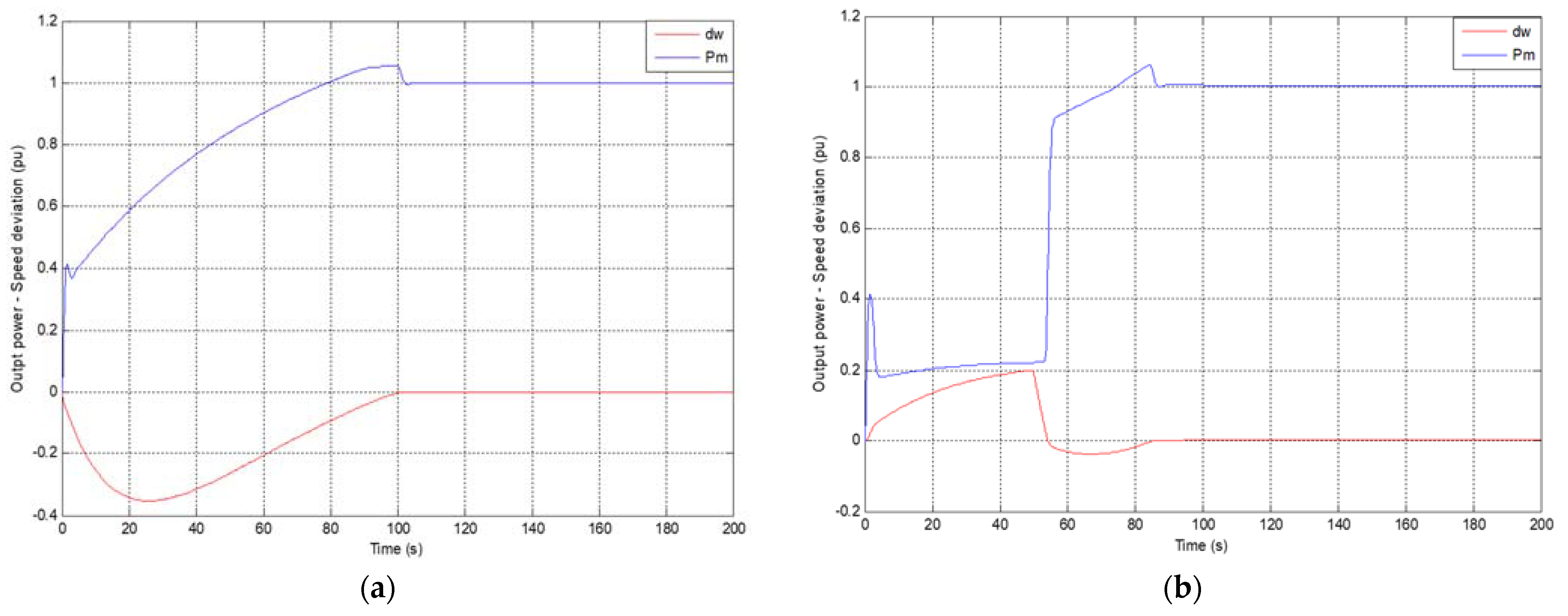
Figure 6 illustrates that, for a step change in load at
t = 0 s, the frequency drops in the transient time and then remains at its nominal value (no frequency deviation, Δ
f = 0 Hz). At time
t = 50 s, a step load is applied to the system. When there is no load, the frequency deviation reaches Δ
f = + 0.2 Hz; at
t = 50 s it falls to Δ
f = −0.03 Hz. After that, the frequency returns to its nominal value, as does the output power, during the steady state.
8. Conclusions
The dynamic responses to load and damping changes, which are expressed by a change in frequency, are presented in this paper. Depending on the speed deviation characteristics and the frequency sensitivity to the load change, the action of the speed governor control results in a steady-state frequency deviation. The output power of the CCGT remains at more or less its rated value, until the frequency of the system returns to its nominal value. As the frequency depends on the output power, the frequency should remain nearly constant in order to maintain the speed generator at its rated value. Consequently, the reliability and effectiveness of the frequency control system is necessary for the stability of power system generation.
Author Contributions
Conceptualization, writing—review and editing, D.T.; visualization and supervision, H.B. All authors have read and agreed to the published version of the manuscript.
Funding
This research received no external funding.
Conflicts of Interest
The authors declare no conflict of interest.
Appendix A
Table A1.
Simulation parameters used in this study [
8].
Table A1.
Simulation parameters used in this study [
8].
| Symbol | Description | Value |
|---|
| Compressor inlet temperature | 30 °C |
| Compressor discharge temperature | 390 °C |
| Gas turbine inlet temperature | 1085 °C |
| Gas turbine exhaust temperature | 535 °C |
| Compressor pressure ratio | 11.5 |
| Ratio of specific heat | 1.4 |
| Compressor efficiency | 0.85 |
| Turbine efficiency | 0.85 |
| R | Speed Regulation | 0.04 |
| Temperature control integration rate | 0.469 |
| Temperature control upper limit | 1.1 |
| Temperature control lower limit | 0 |
| Fuel control upper limit | 1.5 |
| Fuel control lower limit | 0 |
| Valve positioner time constant | 0.05 |
| Fuel system time constant | 0.4 |
| Air control time constant | 0.4669 |
| Compressor volume time con-stant | 0.2 |
| Gas turbine output coefficient | 0.0033 |
| Steam turbine output coefficient | 0.00043 |
| Governor time constant | 0.05 |
| Gain of radiation shield (instantaneous) | 0.8 |
| Gain of radiation shield | 0.2 |
| Radiation shield time constant | 15 |
| Thermocouple time constant | 2.5 |
| Temperature control time constant | 3.3 |
| Ratio of fuel adjustment | 0.77 |
| Fuel valve lower limit | 0.23 |
| Time constant heat capacitance of waste heat recovery boiler | 5 |
| Boiler storage time constant | 20 |
| Turbine rotor time constant | 18.5 |
References
- Raja, A.J.; Christober Asir, R.B.D.; Thiagarajan, C.C.Y. Frequency Excursion and Temperature control of Combined Cycle Gas Plant Including SMES. Int. J. Comput. Electr. Eng. 2010, 2, 1793–8163. [Google Scholar] [CrossRef] [Green Version]
- Talah, D.; Bentarzi, H. Ambient Temperature Effect on the Performance of Gas Turbine in the Combined Cycle Power Plant. Algerian J. Env. Sci. Technol. 2021. Available online: https://www.aljest.net/index.php/aljest/article/view/513 (accessed on 17 January 2022).
- Spath, P.L.; Mann, M.K. Life Cycle Assessment of a Natural Gas Combined Cycle Power Generation System; National Renewable Energy Lab.: Golden, CO, USA, 2000.
- Kundur, P. Control of Active Power and Reactive Power. Power System Stability and Control; McGraw-Hill: New York, NY, USA, 1994; pp. 581–601. [Google Scholar]
- Kakimoto, N.; Baba, K. Performance of Gas Turbine-Based Plants During Frequency Drops. IEEE Trans. Power Syst. 2003, 18, 1110–1115. [Google Scholar] [CrossRef]
- Mantzaris, J.; Vournas, C. Modelling and Stability of a Single-Shaft Combined Cycle Power Plant. Int. J. Thermodyn. 2007, 10, 71–78. [Google Scholar]
- Lalor, G.; O’Malley, M. Frequency Control on an Island Power System with Increasing Proportions Combined Cycle Gas Turbines. In Proceedings of the IEEE Bologna Power Tech Conference, Bologna, Italy, 23–26 June 2003. [Google Scholar]
- Rai, J.N.; Naimul Hasan, A.B.B.; Garai, R.; Rahul Kapoor, I. Performance Analysis of CCGT Power Plant using MATLAB/Simulink Based Simulation. Int. J. Adv. Res. Technol. 2013, 2, 285–290. [Google Scholar]
- Rowen, W.I. Simplified Mathematical Representation of Heavy Duty Gas Turbines. J. Power 1983, 105, 865–869. [Google Scholar] [CrossRef]
- Lindsley, D. Power Plant Control and Instrumentation; The Institution of Electrical Engineers: London, UK, 2005; pp. 10, 25–46. [Google Scholar]
- Gezer, D.; Taşcıoğlu, Y.; Çelebioğlu, K. Frequency Containment Control of Hydropower Plants Using Different Adaptive Methods. Energies 2021, 14, 2082. [Google Scholar] [CrossRef]
- Lalor, G.; Ritchie, J.; Flynn, D.; O’Malley, M. The Impact of Combined Cycle Gas Turbine Short-Term Dynamics on Frequency Control. IEEE Trans. Power Syst. 2005, 20, 1456–1464. [Google Scholar] [CrossRef]
- Bevrani, H. Robust Power System Frequency Control, 2nd ed.; Springer: Cham, Switzerland, 2014; pp. 23–26. [Google Scholar]
| Publisher’s Note: MDPI stays neutral with regard to jurisdictional claims in published maps and institutional affiliations. |
© 2022 by the authors. Licensee MDPI, Basel, Switzerland. This article is an open access article distributed under the terms and conditions of the Creative Commons Attribution (CC BY) license (https://creativecommons.org/licenses/by/4.0/).


