Proceeding Paper

IOT Based Fault Detection and Protection of Power Transformer in the Smart Grid †

by
Muhammad Kashif Sattar
1,*,
Muhammad Waseem
2,3,*,
Saqib Fayyaz
4,
Riffat Kalsoom
5,
Hafiz Ashiq Hussain
1 and
Muhammad Shahzar Saddique
3
1
Department of Electrical Engineering, HITEC University, Taxila 47070, Pakistan
2
School of Electrical Engineering, Zhejiang University, Hangzhou 310027, China
3
Department of Electrical Engineering, University of Engineering and Technology, Taxila 47080, Pakistan
4
Department of Electrical, Government College of Technology (GCT), Rawalpindi 46000, Pakistan
5
Department of Physics, HITEC University, Taxila 47070, Pakistan
*
Authors to whom correspondence should be addressed.
Presented at the 1st International Conference on Energy, Power and Environment, Gujrat, Pakistan, 11–12 November 2021.
Eng. Proc. 2021, 12(1), 7; https://doi.org/10.3390/engproc2021012007
Published: 22 December 2021
(This article belongs to the Proceedings of The 1st International Conference on Energy, Power and Environment)

Abstract

:
This paper presents a novel Arduino-based fault detection and protection system for power transformers. Power transformers are an integral component of the power system infrastructure. Power transformers are present in such a significant number in the power architecture that any alteration in its operation effects the whole power system. The optimal operation of the transformer depends upon its operating condition; for this reason, its monitoring and protection are very important. Currently, power transformers employ differential relays to ensure optimal operation, but differential relays are unable to ascertain conditions such as overloading and intra turn faults. In this paper, Arduino was used to monitor transformer operation instead of differential relays and generate tripping or alert signals based on sensed values. Arduino autonomously sensed the current, voltage, and temperature values of the power transformer round the clock and handled any fault by comparing preset values of these parameters. In addition, the differential relay functionality of fault detection was implemented in the Arduino environment. Whenever a fault occurred, Arduino sent the fault signal to a Wi-Fi module, which was then displayed in the Blynk app. The practical implementation of this proposed system was tested, and its operation was found to be effective in fault detection.

1. Introduction

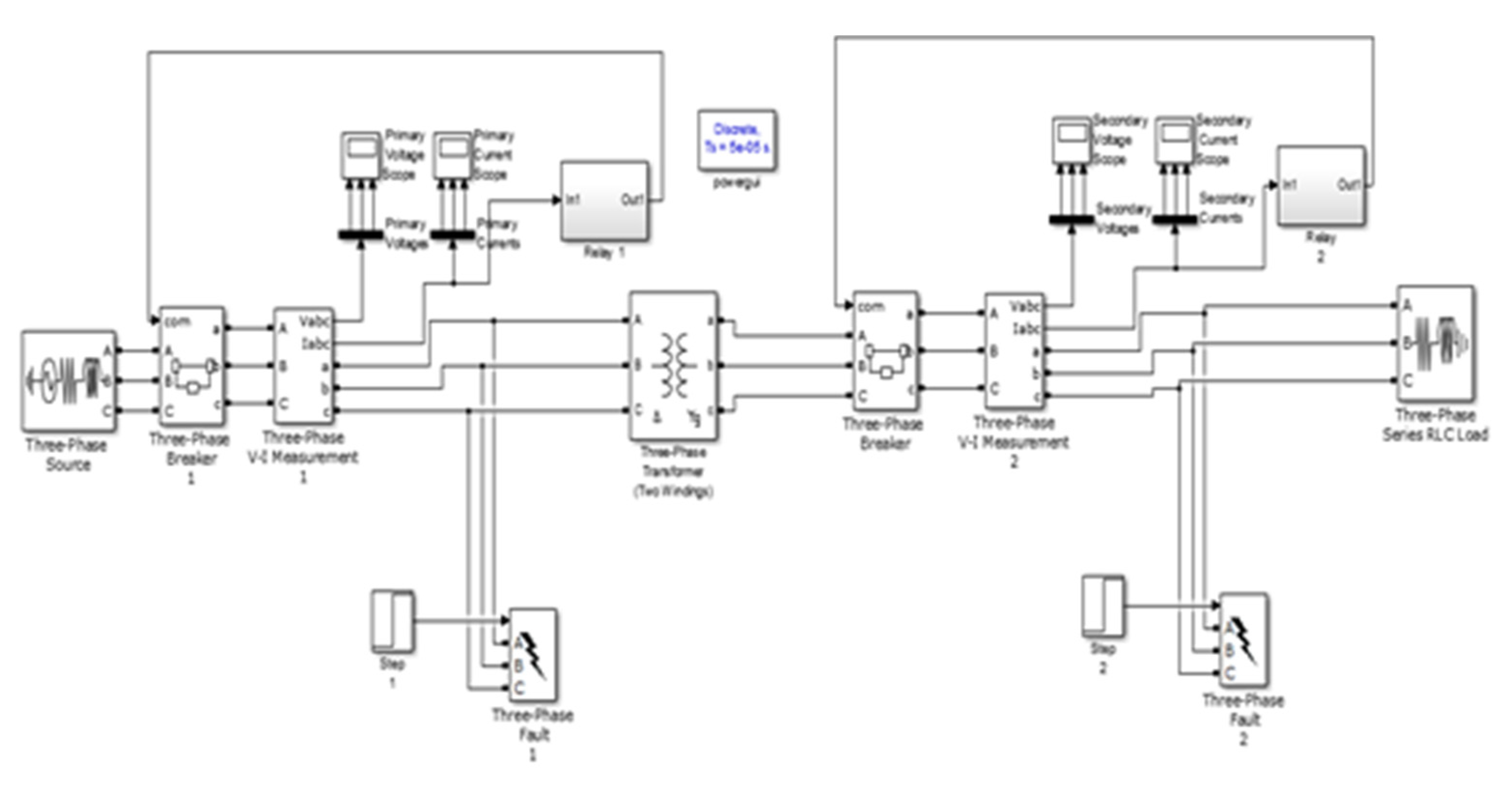
Transformers are the most common electrical power system component that we encounter in our daily lives. Especially in countries where overhead distribution systems are in place, the presence of transformer cannot be overlooked. Power transformers are used in power systems to transfer electrical energy by stepping either up or down the voltage level. Normally, power transformers step down the voltage from 500 kV or 120 kV to 11 kV at the distribution end. Transformers are known to be very resilient and show remarkable efficiency in real-world scenarios. However, the excess of faults due to uncertain increase in load day by day may cause malfunction, insulation break down, or complete failure of transformers, resulting in a blackout [1]. Transformers are key components and most expensive devices in power systems, so their protection is very important for the stability of power system [2,3,4]. Differential protection is the primary protection of transformers in which currents from both current transformers (CTs), primary as well as secondary currents, are taken into an account and the difference of both the currents is compared with the pickup value of the relay. If the difference is equal or more than the pickup value, the relay will operate and give a tripping signal to a circuit breaker and the circuit will trip [5,6,7,8,9]. The basic differential relay-based protection structure for the transformer protection is effective for most faults, but it will not work for other faults such as overcurrents and rise in temperature of winding and oil in transformers. For the thermal protection of transformers, “Buchholz relays” are used as a safety device mounted on the transformers, equipped with an external overhead oil reservoir called a “conservator”. In this paper, an Arduino-based alternate protection scheme is proposed. The block diagram of the proposed method is shown in Figure 1.

2. Proposed IoT-Based Protection Scheme for Power Transformers

In this paper, Arduino was used for monitoring faults and consequently based on the monitoring to generate the corresponding signal to trip a circuit breaker. The given scheme is to be designed for the monitoring, displaying, and controlling of parameters such as values of primary/secondary voltages, currents, and temperatures of the transformer in real time. Voltage was sensed by the Arduino from a potential transformer (PT) which related to a bus bar and a current from a CT which was connected to measure the line currents. An LM-35 Temperature Sensor was used to measure the temperature of the transformer. Relays were used to perform the tripping operation. The values of voltage, current, and temperature were displayed on the LCD [10,11]. An Arduino ATmega328 microcontroller including 16 MHz crystal was used for implementing the controlling system. Programming was performed in C language [12]. Differential protection was very important for all the devices in power systems [13].
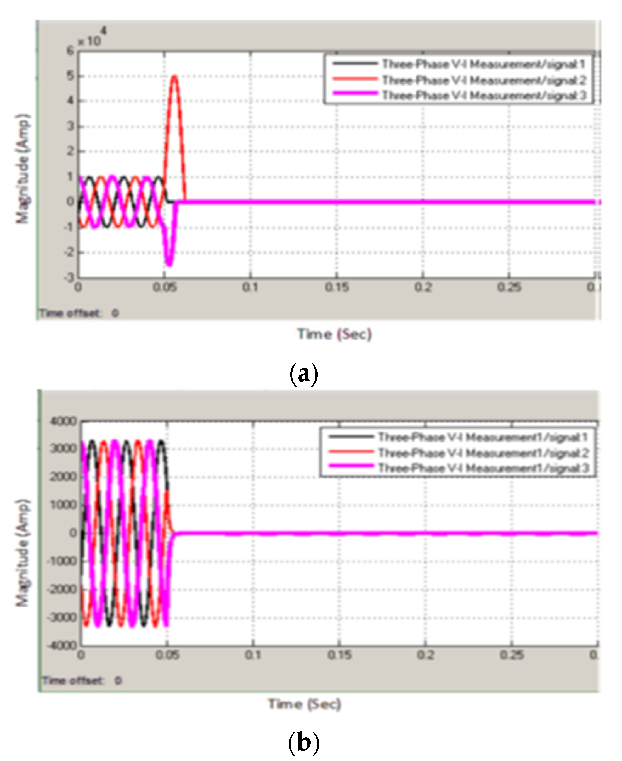
Figure 1 shows the simulation diagram in Simulink MATLAB for the differential protection of the transformer. In the given simulation, the primary and secondary currents in the form of the RMS values of all the three phases will be from the CT. As the value of one side of the transformer was less than that of the other due to the property of Step up/down, so for that take, the gain on one side with the Vp/Vs ratio Ip was equal to the other side current Is, making the values of the currents equal at both sides. The values of both the primary and secondary currents were subtracted to check the pickup value for differential relays. If the difference of these values was greater or equal to the setting of the differential relays, a trip signal was given to the breaker. The primary and secondary current waveforms when fault was inserted at the time of 0.05 s with an offset of zero are given in Figure 2a,b respectively. As differential relays did not work for the fault, which was outside the zone, we needed one more relay which was named as external relay. The simulation results are shown in Figure 3, and the result of the current after the fault when inserted at 0.15 s is shown in Figure 4. As both the relays worked only for their own settings, all these faults were monitored and protected by a single relay named as Arduino.

2.1. Outputs on Blynk App on a PC or Mobile Phone

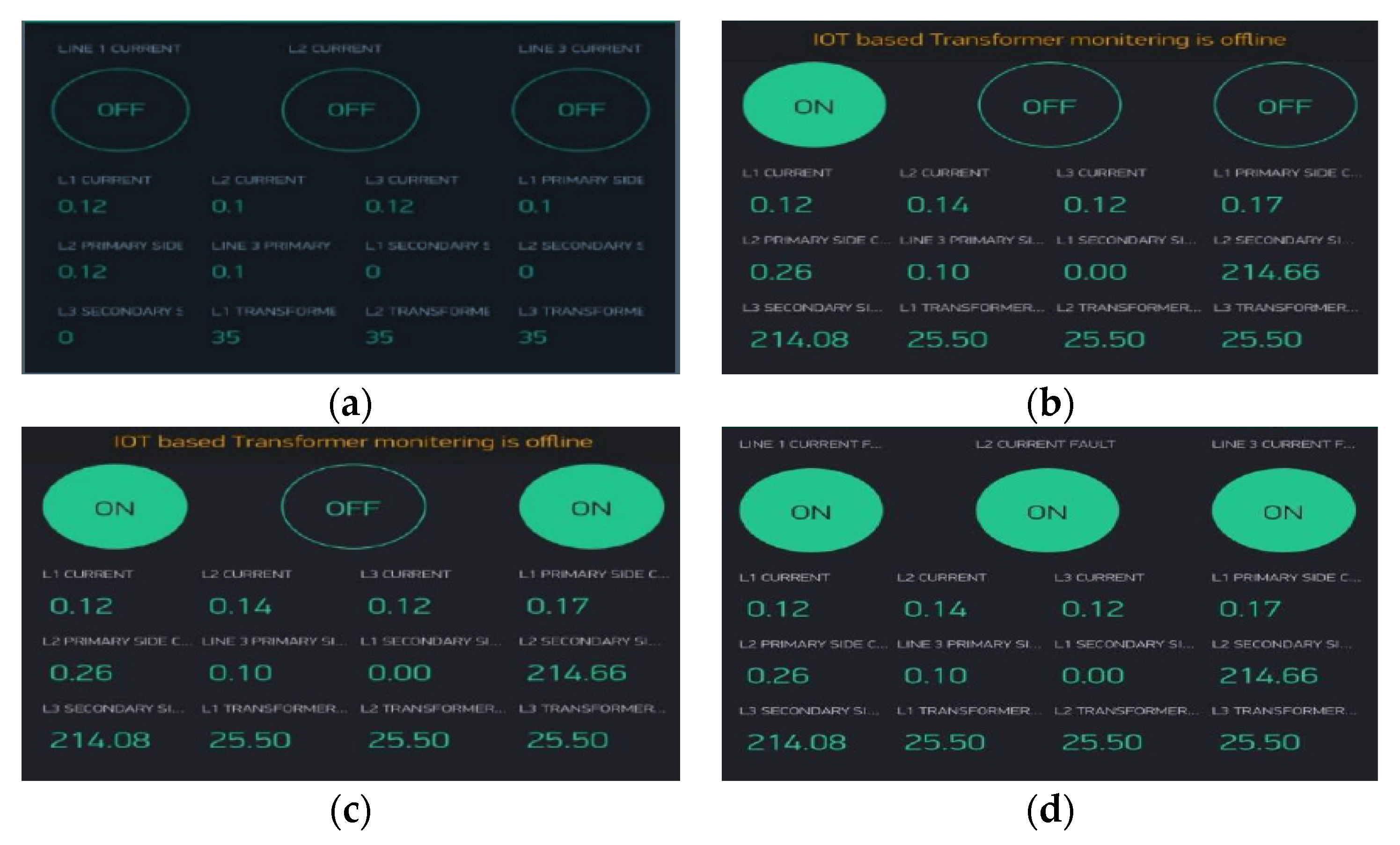
Blynk is designed to provide an interface for IoT applications. It enables remote appliance control and sensor monitoring. It is easy to setup and use. Through blynk, we can have a look at different fault conditions, create fault conditions and validate appropriate actions taken by our Arduino-based protection scheme. Here are the results of different types of faults including symmetrical and unsymmetrical faults on our system. These faults can be generated manually or with the help of the app. Thus, with the help of the app, all the faults were generated, and their values are given below. Figure 5a shows the results under no fault conditions. Figure 5b represents the line-to-ground fault, in which one line was short-circuited with the ground, making the line-to-ground fault. Therefore, in this way, one can generate the line-to-ground fault by using websites.
Figure 5c represents line-to-line-to-ground fault, in which one line was short-circuited with the ground, making the line-to-line-to-ground fault. Therefore, in this way, one can generate the line-to-line-to-ground fault by using websites. In this situation, both lines gave rise to the unsymmetrical component of fault, because it is the type of unsymmetrical fault. The current range changes gave rise to the highest current in both lines. Figure 5d shows the line-to-line-to-line-to-ground fault, in which one line was short-circuited with the ground, making the line-to-line-to-line-to-ground fault. In this way, we can see the currents in all the lines and the voltage levels of the transmission lines. Table 1 shows the effect of the change in temperature and action taken by the protection scheme. Our system was preset at 35 °C to turn on the cooling system. If the temperature of 400 °C was reached, the scheme tripped the transformer while the fan was kept on.

2.2. Comparison with Other Relays

From above discussion, it is quite evident that the proposed Arduino-based IoT-enabled protection scheme can handle all transformer faults encountered as a standalone device. The results achieved were found in accordance with the simulations performed as per the desired outputs. As indicated by Table 2, the functionality of the proposed scheme encompassed all available protection options that the current protection devices provided as a standalone all-in-one cost-effective solution.

3. Conclusions

In this paper, an Arduino-based fault detection and monitoring system for power transformers in the smart grid environment was introduced. Arduino served as the core of the whole structure and monitored the key parameters such as the current, voltage, and temperature of the system using a CT, a PT, and an LM 35 sensor. Practical scenarios created upon prototype indicated that the system worked accurately as proposed and made decisions in accordance with theoretical preset values. The voltage protection system ensured the operation of the transformer in the range from 180 to 240 V; the current protection system ensured operation in the range, whereas the temperature protection system ensured operation in the range from 0 to 400 °C. The Arduino compared the sensed values with a preset value and sent the fault signal to a Wi-Fi module on Blynk app. Blynk app provided an interface to monitor, simulate and validate the protection scheme under faults. The protection scheme achieved desired output, proving its effectivity in providing a cost-effective solution for all transformer faults.

Author Contributions

Conceptualization, M.K.S., M.W. and S.F.; methodology, M.K.S. and M.W.; software, M.K.S.; validation, M.K.S., M.W., R.K. and S.F.; formal analysis, M.K.S., M.W., S.F., R.K., H.A.H. and M.S.S.; investigation, M.K.S. and M.W.; resources, M.K.S.; writing—original draft preparation, M.K.S., M.W., S.F., R.K., H.A.H. and M.S.S.; writing—review and editing, M.K.S., M.W., S.F., R.K. and M.S.S.; visualization, H.A.H.; supervision, H.A.H.; project administration, S.F. and M.W.; funding acquisition, M.K.S., M.W. and S.F. All authors have read and agreed to the published version of the manuscript.

Funding

This research received no external funding.

Institutional Review Board Statement

Not applicable.

Informed Consent Statement

Not applicable.

Data Availability Statement

All the data is available in cited papers.

Conflicts of Interest

The authors declare no conflict of interest.

References

  1. Rizwan, M.; Hong, L.; Waseem, M.; Shu, W. Sustainable protection coordination in presence of distributed generation with distributed network. Int. Trans. Electr. Energy Syst. 2020, 30, e12217. [Google Scholar] [CrossRef]
  2. Tajdinian, M.; Allahbakhshi, M.; Bagheri, A.; Samet, H.; Dehghanian, P.; Malik, O.P. An enhanced sub-cycle statistical algorithm for inrush and fault currents classification in differential protection schemes. Int. J. Electr. Power Energy Syst. 2020, 119, 105939. [Google Scholar] [CrossRef]
  3. Jamal, H.; Waseem, M.; Sajjad, I.A.; Anjum, A.; Khan, M.S. Low-Cost Feedback Control Thermal Protection System for 3-Phase Distribution Transformer Using Microcontroller. In Proceedings of the 2018 IEEE International Conference on Smart Energy Grid Engineering (SEGE), Oshawa, ON, Canada, 12–15 August 2018; pp. 200–204. [Google Scholar]
  4. Rizwan, M.; Hong, L.; Waseem, M.; Ahmad, S.; Sharaf, M.; Shafiq, M. A Robust Adaptive Overcurrent Relay Coordination Scheme for Wind-Farm-Integrated Power Systems Based on Forecasting the Wind Dynamics for Smart Energy Systems. Appl. Sci. 2020, 10, 6318. [Google Scholar] [CrossRef]
  5. Iqbal, M.M.; Waseem, M.; Manan, A.; Liaqat, R.; Muqeet, A.; Wasaya, A. IoT-Enabled Smart Home Energy Management Strategy for DR Actions in Smart Grid Paradigm. In Proceedings of the 2021 International Bhurban Conference on Applied Sciences and Technologies (IBCAST), Islamabad, Pakistan, 12–16 January 2021; pp. 352–357. [Google Scholar]
  6. Waseem, M.; Lin, Z.; Liu, S.; Sajjad, I.A.; Aziz, T. Optimal GWCSO-based home appliances scheduling for demand response considering end-users comfort. Electr. Power Syst. Res. 2020, 187, 106477. [Google Scholar] [CrossRef]
  7. Aziz, T.; Lin, Z.; Waseem, M.; Liu, S. Review on optimization methodologies in transmission network reconfiguration of power systems for grid resilience. Int. Trans. Electr. Energy Syst. 2021, 31, e12704. [Google Scholar] [CrossRef]
  8. Iqbal, M.M.; Sajjad, I.A.; Manan, A.; Waseem, M.; Ali, A.; Sohail, A. Towards an Optimal Residential Home Energy Management in Presence of PV Generation, Energy Storage and Home to Grid Energy Exchange Framework. In Proceedings of the 2020 3rd International Conference on Computing, Mathematics and Engineering Technologies (iCoMET), Islamabad, Pakistan, 29–30 January 2020; pp. 1–7. [Google Scholar]
  9. Waseem, M.; Sajjad, I.A.; Chicco, G. Seasonal Effect on the Flexibility Assessment of Electrical Demand. In Proceedings of the 2018 53rd International Universities Power Engineering Conference (UPEC), Glasgow, UK, 4–7 September 2018; pp. 1–6. [Google Scholar]
  10. Wilcher, D. Learn Electronics with Arduino; Knowledge Rapid Series; Apress: New York, NY, USA, 2012. [Google Scholar]
  11. Usman, M.; Waseem, M.; Khan, D.; Manan, A.; Ullah, S.; Iqbal, M.M.; Faheem, Z.B. PD Based Cost Effective and Accurate Calorimeter Temperature Control and Measurement System. In Proceedings of the 2020 IEEE International Conference on Sustainable Engineering and Creative Computing (ICSECC), Cikarang, Indonesia, 16–17 December 2020; pp. 189–193. [Google Scholar]
  12. Naseem, A.; Alam, N. Protection of distribution transformer using Arduino platform. Sci. Int. 2015, 27, 403–406. [Google Scholar]
  13. Fayyaz, S.; Sattar, M.K.; Waseem, M.; Ashraf, M.U.; Ahmad, A.; Hussain, H.A.; Alsubhi, K. Solution of Combined Economic Emission Dispatch Problem Using Improved and Chaotic Population-Based Polar Bear Optimization Algorithm. IEEE Access 2021, 9, 56152–56167. [Google Scholar] [CrossRef]
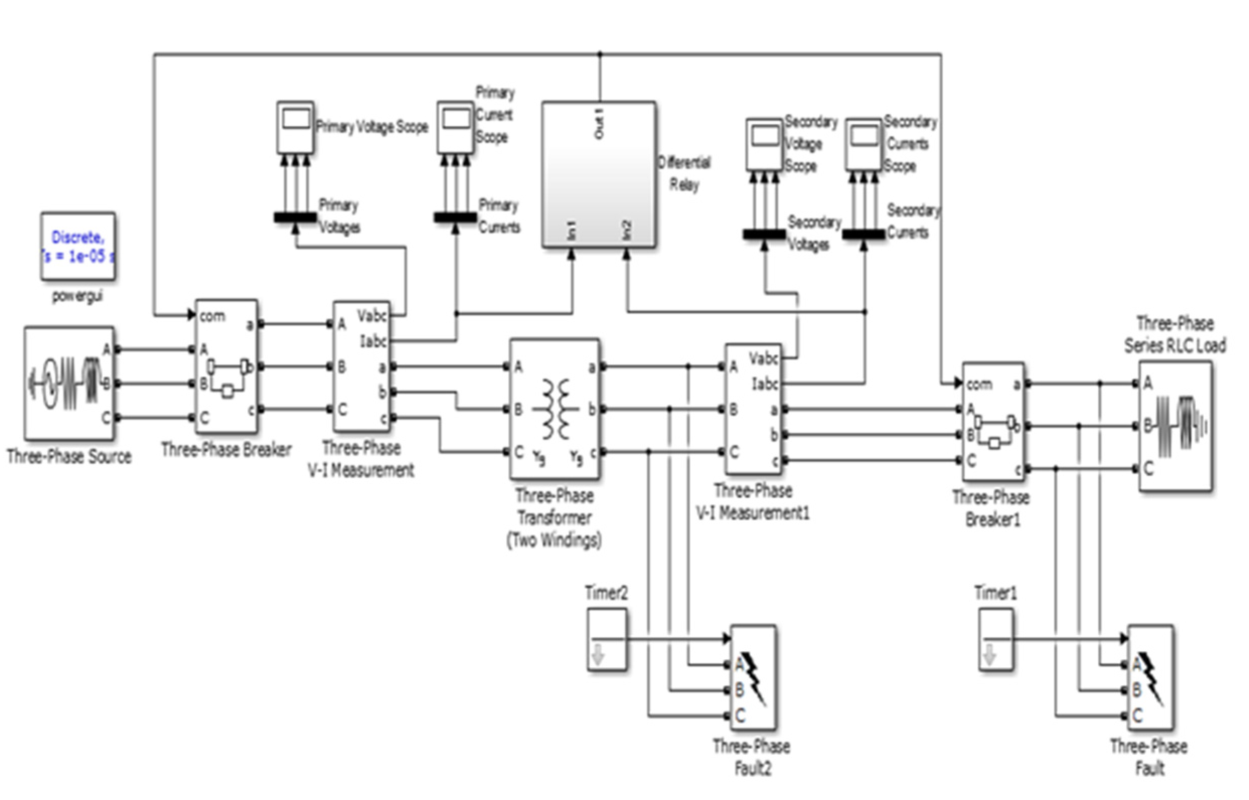
Figure 1. Arduino-based IoT-enabled differential protection for the power transformer.
Engproc 12 00007 g001
Figure 2. (a,b) Primary and secondary current waveforms of the power transformer.
Engproc 12 00007 g002
Figure 3. Arduino-based IoT-enabled external protection for the power transformer.
Engproc 12 00007 g003
Figure 4. Current waveforms after fault for the power transformer.
Engproc 12 00007 g004
Figure 5. Results of different types of faults with the BLYNK application: (a) readings and state of the transformer at normal conditions; (b) line-to-ground fault through fault switching L-L; (c) line-to-Line to ground fault on lines L1 and L3 (LLG fault); (d) line-to-line-to-line ground fault (LLLG Fault).
Engproc 12 00007 g005
Table 1. Effect of the temperature variation on the cooling system.
Sr. No.Temperature (°C)Output VoltageFan Status
1250.25 VOff
2300.30 VOff
3350.35 VOn
4400.40 VOn & system trips
Table 2. Comparison of different relays with the proposed relaying system.
Fault TypesPercentage Differential Relay Buchholzs RelayIDMTOur Scheme
Over voltage
Over current
Differential
Thermal
Publisher’s Note: MDPI stays neutral with regard to jurisdictional claims in published maps and institutional affiliations.