Abstract
This article presents a 2D pose estimation method for an omnidirectional mobile robot with Mecanum wheels, using an extended Kalman filter (EKF) formulated on the Lie group . The purpose is estimate the robot’s position and orientation by fusing angular velocity measurements from the wheel encoders with data from an IMU. Employing Lie algebra, the EKF provides a consistent and compact representation of rotational motion, improving prediction and update steps. The filter was implemented in ROS 1 and validated in simulation using Gazebo, with a reference trajectory and real measurements used for evaluation. The system delivers higher pose estimation precision, validating the effectiveness in rotational maneuvers.
Keywords:
extended kalman filter; fusion; IMU; Lie algebra; odometry; pose estimation; ROS; sensor fusion; SO(2) 1. Introduction
Robust and accurate pose estimation is a fundamental requirement in mobile robotics, enabling key capabilities such as localization, mapping, motion control, and autonomous navigation. In planar systems, the pose typically comprises the robot’s position and orientation relative to a global coordinate frame. However, when relying on low-cost onboard sensors—such as wheel encoders and inertial measurement units (IMUs)—the estimation process is susceptible to various sources of error, including noise, drift, and asynchronous sampling [1]. These challenges are exacerbated in omnidirectional robots equipped with Mecanum wheels, which are particularly prone to lateral slip and imperfect ground contact, making odometry-based measurements less reliable [2].
To address these limitations, sensor fusion techniques have become widely adopted, with the extended Kalman filter (EKF) emerging as one of the most commonly used frameworks for nonlinear state estimation in robotics [3]. Traditional EKF implementations often represent orientation using Euler angles or unit quaternions. While these methods are computationally efficient, they suffer from well-known drawbacks: Euler angles are subject to singularities such as gimbal lock, and quaternions introduce redundancy and require continuous normalization [4]. These shortcomings can compromise the consistency and stability of the filter, particularly under high angular velocities or in the presence of sensor uncertainty.
Recent research has demonstrated that formulating estimation filters on Lie group manifolds can offer more mathematically consistent and compact representations of rotational motion. By defining the EKF directly on the Lie group —which describes planar rotations—it is possible to maintain minimal representations that preserve the geometric structure of the state space [5,6]. These Lie group-based EKFs, also known as Discrete Lie Group EKFs (D-LG-EKFs), have been successfully applied in various robotic domains such as inertial navigation, human motion tracking, and SLAM, often showing improved accuracy and robustness compared to their Euclidean counterparts [7].
Several studies have also explored the integration of these estimation techniques within robotic middleware platforms such as the Robot Operating System (ROS). For instance, Moore and Stouch [8] proposed a generalized EKF framework compatible with ROS-based systems, while Park et al. [9] evaluated the timing behavior of ROS 2.0 in multi-agent environments. Nevertheless, the application of Lie group-based EKFs to omnidirectional ground robots—particularly those relying exclusively on onboard inertial and wheel encoder data—remains limited. In such platforms, where accurate localization is crucial and external references (e.g., motion capture systems) may not be available, a reliable onboard estimator is essential.
In this work, we propose a real-time 2D pose estimation framework for omnidirectional mobile robots with Mecanum wheels, based on an extended Kalman filter formulated on the Lie group . The proposed system fuses angular velocity measurements from each wheel with inertial data from an IMU to estimate the robot’s planar position and orientation. The EKF was designed to operate directly on the Lie algebra , enabling a minimal and geometrically consistent treatment of orientation updates. The full estimation pipeline was implemented in C++ within the ROS Noetic environment, using message filters to synchronize asynchronous sensor streams. The mathematical model incorporates a discrete-time motion model for wheel-based odometry and a measurement model that integrates acceleration, angular velocity, and magnetic orientation. The validation experiment was performed in: (i) simulation using Gazebo, RViz, and realistic noisy sensor inputs, and (ii) real implementation on an omnidirectional mobile robot from the Hiwonder series. Unlike prior works that rely on external ground truth systems for correction, our approach uses only onboard sensing—making it applicable for low-cost robotic platforms. Results demonstrate that the Lie group-based EKF improves estimation consistency and robustness, particularly during rotational maneuvers with lateral slip, providing a practical solution for embedded localization in omnidirectional systems. Note that a key limitation of the present work is that the EKF formulation does not include explicit bias estimation, since the IMU is treated solely as an update tool rather than as part of the state vector. As a result, the filter cannot fully compensate for gyro bias and related drift, which may impact orientation accuracy in certain trajectories. In addition, the scope of our experimental validation is constrained by the availability of ground truth: the optical tracking system used is limited to a [m2] capture area, which restricts the duration and spatial extent of the runs that can be evaluated. This work was formulated under the assumption of a purely 2D pose estimation, where the robot is constrained to planar motion. As a result, the filter does not estimate inclination or compensate for gravity effects, which restricts its applicability to flat environments. This simplification reduces complexity but limits performance in scenarios involving ramps, slopes, or uneven terrain, and we identify this as an area for improvement in future extensions of the model.
2. Methodology
To improve the 2D pose estimation of an omnidirectional mobile robot, we propose a sensor fusion scheme that combines odometry derived from wheel encoders with inertial measurements from an onboard IMU. This approach is specifically designed to mitigate errors caused by wheel slippage, a common issue in mecanum-wheeled platforms operating on low-friction surfaces. Since the encoder and IMU data streams operate at different sampling frequencies and arrive asynchronously—60 Hz for the wheel encoders and 100 Hz for the IMU—it is necessary to perform timestamp alignment prior to state estimation. To address this, we use ROS message filters to synchronize the incoming data and downsample all measurements to the rate of the slower sensor. The proposed estimation framework is implemented on a Hiwonder omnidirectional robot equipped with four mecanum wheels, a Jetson Nano onboard computer, and the Robot Operating System (ROS). This synchronized sensor data is then used as input to an extended Kalman filter (EKF) operating on a Lie group-based state representation, as summarized in Figure 1.
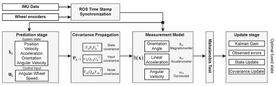
Figure 1.
Extended Kalman filter scheme for sensor fusion.
The EKF is formulated within the mathematical framework of Lie groups, where the robot’s orientation is represented as an element of the special orthogonal group , enabling consistent handling of rotations and avoiding the singularities or discontinuities commonly associated with angle-based representations [4]. The following subsections bring details of the EKF stages.
2.1. State Prediction
The prediction stage propagates the system state forward in time using a discrete-time motion model driven by the control input derived from wheel odometry. This model estimates the evolution of the system state under the assumption of piecewise constant input during each sampling interval. The integration is performed on the appropriate manifold, preserving the geometric structure of the state space, where vector quantities evolve in and the orientation is updated through the exponential map on . The system state at time k is defined as
where denotes the position, the linear velocity, the linear acceleration, the orientation matrix, and the angular velocity expressed in the Lie algebra of . All variables are defined for a 2D planar system, referred to a global reference frame, and the bold notation indicates vector- or matrix-valued quantities. The error state is modeled as a Gaussian distribution with a mean , a covariance , and expressed as , where the orientation error falls within the tangent space . The proposed state transition is modeled as follows:
where it includes the noise perturbations originating from the control input and from the random walk for the linear acceleration . The noise is modeled as a Gaussian distribution with mean 0 and covariances , respectively. Recall that the noise is a continuous white-noise signal, and hence, it must be sampled over a step time . The integration of these random impulses over a step time [7,10] yields, , and , where is the noise associated with the linear acceleration, and is the noise associated with the angular velocity of each wheel. The operator ⊕ denotes a Lie group exponential map defined as . The input control signal is related to the wheel’s angular velocity as , and terms and are deduced from the omnidirectional robot’s kinematic model [2], yielding
where is the wheel’s radius, and and are the half width and length of the robot.
2.2. Covariance Propagation
The EKF propagates the uncertainty associated with the estimated state by evolving the error covariance matrix. This propagation is performed using a linearized approximation of the nonlinear system dynamics around the current state estimate. The state covariance is propagated as where , , and are the Jacobians of the state, control input noise, and system noise respectively. The Jacobian terms are mostly zero or identity matrices, but those Lie group variables require special attention in their derivation. The Jacobian matrices are
Note that we define as an identity matrix of . The Jacobians terms follow the notation to denote . We rely on Sola et al. [4] to derive the rotation Jacobians based on the Lie algebra, yielding
where denotes a skew symetric matrix of 1. The remaining terms concerning the noise covariance are mostly diagonal matrices. The process noise covariance is defined as with a trivial Jacobian . The control signal Jacobian is also a diagonal matrix that yields .
2.3. State Measurement Model
The measurement model incorporates sensor observations to correct the predicted state. In our formulation, we consider fusing the data from three sensors: a magnetometer (providing absolute orientation), an accelerometer, and a gyroscope. The measurement function maps the current state to predicted sensor outputs; we propose the following measurement model:
Here, is the orientation angle extracted from the rotation matrix using the logarithmic map, is the expected acceleration in the world frame at the IMU location , which includes the centripetal effect due to the rotational motion, and is the angular velocity. The innovation (or residual) vector is computed as
where the terms with notation are obtained from the IMU. The Jacobian of the measurement model is computed as
with . This Jacobian is used to propagate the innovation covariance, yielding where the covariance noise term is related to the sensor specifications and it can be expressed as . To improve the robustness of the filter against outliers, we apply a Mahalanobis distance test to each innovation before performing the state update. The Mahalanobis distance takes into account both the magnitude and the covariance structure of the innovation. A measurement is considered as valid if its Mahalanobis distance falls below two standard deviations [11] as .
2.4. State Update
Upon Mahalanobis test satisfaction, we update the state following the Kalman filter steps, yielding: (i) Kalman gain: , (ii) Observed error: (iii) State update: , and (iv) Covariance update: . Note that the ⊕ operator denotes a simple sum for the real terms during the state update; however, the rotation is updated following the Lie algebra as .
3. Results
The experiment results were obtained from controlled trials in both simulated and physical settings. In simulation, we used a Gazebo implementation based on a previous work [12], taking the simulator-provided ground-truth trajectory as the reference and comparing an extended Kalman filter (EKF) pose estimate and a wheel-odometry estimate. Complementary experiments were conducted on an omnidirectional mobile robot with mecanum wheels, where sensor data came from wheel encoders and a WitMotion IMU; the EKF and odometry 2D pose estimation were compared against an external ground-truth solution based on a low-error visual algorithm developed in a previous work [13], which is under a publication process.
The noise terms were tuned based on the sensor specifications and taking into account a sample time of approximately 50 [Hz], which belongs to the maximum acquisition frequency for the wheels’ odometry. The noise values used are as follows: linear acceleration noise [m/s2 ], wheel speed noise [rad/s], IMU linear acceleration noise [m/s2 ], IMU gyroscope noise [rad/s] and IMU magnetometer noise [rad/s]. Additionally, the kinematic model requires geometric constants specific to the omnidirectional robot from the Hiwonder series. The wheel radius is [m] and the semi-axis longitudinal and lateral are [m] and [m].
The experimental validation was carried out across three different trajectories as shown in Figure 2, where the plots come from a trajectory controller implemented on the omnidirectional robot. Recall that we are not assessing the precision of the controller, just the 2D pose estimation performance. The top row in Figure 2 belongs to a real implementation compared against an external ground-truth, while the bottom row comprises the simulated results in a Gazebo environment.
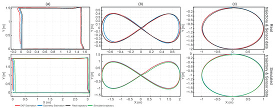
Figure 2.
Trajectory estimation results: (a) rectangular trajectory; (b) lemniscate trajectory; (c) circular trajectory.
Across the three trajectories, the EKF and the wheel odometry reproduce the simulated paths almost perfectly (see red lines in Figure 2), indicating that the kinematic model and numerical implementation are internally consistent. In the rectangular path (see Figure 2a), wheel odometry tracks the ground-truth corners and straight segments more closely than the EKF, with the EKF exhibiting slight corner-rounding and small lateral drifts near turns. In contrast, for the smooth figure-eight and elliptical paths in Figure 2b,c, the EKF adheres more tightly to the measured trajectory, while wheel odometry shows curvature-dependent drift (systematic over/under-shoot on arcs), accumulating pose error over the loop. Overall, the EKF provides superior accuracy on smooth, continuously curving motions, whereas wheel odometry is competitive—and occasionally better—on long straight segments with abrupt stops and 90° turns.
The larger errors observed in the rectangular trajectory in Figure 3 can be attributed to the aggressive cornering, where the robot is subjected to lateral slip, encoder quantization, and increased vibration. Under these conditions, the IMU measurements—particularly the magnetometer near motor currents—are more disturbed, and even small time misalignments between encoder and IMU data become significant at high angular rates. Furthermore, slight roll and pitch during turning project gravity into the accelerometer readings, which are not compensated in our 2D formulation. Since the filter covariances were tuned for smoother motion, these effects cause the EKF to over-trust corrupted measurements, resulting in larger discrepancies compared to the lemniscate and circular trajectories, where the dynamics remain more stable and consistent with the model assumptions.
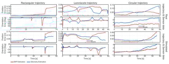
Figure 3.
Errors evolution over time.
The contrasting behavior is consistent with sensing and modeling trade-offs. Wheel odometry performs well on straight segments because encoder integration is low noise and slip is minimal. Sharp corners also limit heading error, since the robot is nearly stationary during heading changes. On smooth curves, the wheel–ground contact and the roller mechanics of mecanum-omni wheels cause small but persistent lateral slip and calibration errors in wheel radius and track width. These errors accumulate into a curvature-dependent position bias, which is exactly where fusing inertial measurements helps. The EKF mitigates this curvature drift by stabilizing heading with gyroscope information, but it can degrade on the rectangular path if (i) gyroscope bias/noise is mis-tuned, leading to over-smoothing and corner rounding; (ii) IMU–encoder timestamps are slightly misaligned, causing filter lag around impulsive yaw-rate changes; (iii) the IMU frame is misaligned by a few degrees with respect to base link; or (iv) the process/measurement covariances overweight the IMU near zero-velocity phases, injecting small heading errors that become lateral offsets after each corner. The good agreement in simulation suggests that these discrepancies are dominated by real-world effects rather than algorithmic faults.
Figure 3 shows the error evolution over time, in position and orientation, for the real and simulated experiments. In the rectangular-real run, the EKF shows large yaw spikes at the turns and a late position jump, while odometry remains near zero; this points to filter issues around impulsive yaw—likely a combination of (i) mis-tuned gyro bias/noise (overweighting the IMU), (ii) a few-ms IMU–encoder timestamp skew that creates lag at corners, and/or (iii) small IMU–base misalignment that converts heading transients into lateral error. In the lemniscate/real case, both estimators drift, but the EKF only partially suppresses curvature-induced error; odometry’s oscillatory error follows curvature, consistent with mecanum slip and minor radius/track calibration bias. In the circular/real run, the EKF clearly dominates: both position and yaw errors grow more slowly than odometry, confirming the value of gyro fusion under sustained curvature. The simulated rows invert part of this pattern—odometry is comparable or better in rectangular and lemniscate—implying the simulator lacks the lateral slip that penalizes odometry in reality, while the EKF remains sensitive to exact IMU statistics and tuning. The circular case favors the EKF in both domains, consistent with heading stabilization by the gyro when curvature persistently excites yaw.
Table 1 and Table 2 present a comparative evaluation of the proposed EKF and the odometry 2D estimator across three reference trajectories: circular, square, and lemniscate. The results indicate that, in general, the EKF achieves improved position accuracy in real-world experiments, particularly in the circular and lemniscate trajectories. These types of paths are characterized by continuous curvature and are more susceptible to wheel slip and drift, where odometry alone accumulates significant error over time. In contrast, the EKF leverages inertial data to reduce this drift, resulting in lower RMS and mean position error. However, in the orientation domain, odometry often outperforms EKF, especially in the square trajectory, where it found lower position error and maximum orientation errors. This behavior may be explained by the abrupt transitions at corners, where the EKF is more sensitive to timing misalignments and inertial sensor noise. However, the maximum orientation errors for the EKF consistently appear at sharp turns rather than along straight-line segments, indicating that high angular rate changes present a challenge for the filter, potentially due to delayed IMU integration or suboptimal noise parameters. However, it is important to note that in the simulation environment, the EKF achieves lower orientation errors overall, suggesting that under ideal conditions—such as precise sensor synchronization and noise-free inputs—the filter effectively manages rotational dynamics.

Table 1.
Simulation and Robot test metrics for the circular and square trajectories. Position in meters; orientation in degrees.
Table 2.
Simulation and Robot test metrics for the lemniscate trajectory.
Across all three trajectories, the EKF’s performance in position estimation is more stable, with RMS and mean position errors typically lower or comparable to odometry. This reinforces the strength of the sensor fusion approach in mitigating encoder noise and slip, especially in real-world environments where ideal conditions are not guaranteed. The orientation estimation remains a limitation for the EKF in sharp cornering cases, suggesting that further improvements such as adaptive covariance tuning, bias correction, or improved timestamp synchronization could enhance heading estimation. To summarize, the EKF provides superior positional robustness in curved or dynamic motion, while odometry may still be preferable in structured paths with straight lines and predictable transitions.
4. Conclusions
This study proposed a real-time 2D pose estimation system for omnidirectional mobile robots with Mecanum wheels, based on an extended Kalman filter (EKF) formulated on the Lie group . The estimator fuses wheel angular velocities with IMU data, enabling a geometrically consistent and drift-resistant estimation of position and orientation. The system was implemented in C++ within the ROS Noetic framework and validated through simulation with three reference trajectories.
The results demonstrated that the Lie group-based EKF improved position accuracy compared to 2D odometry, particularly in curved trajectories such as circular and lemniscate, where slip and drift are more prominent. In contrast, odometry performed slightly better in orientation during straight-line motion or square paths. The maximum orientation errors in the EKF occurred mainly at sharp turns, highlighting sensitivity to rapid angular changes and potential timing misalignments or IMU noise. For trajectories with tight curves or continuous rotation, reducing both linear and angular velocity can minimize slip and improve convergence. Proper tuning of process and measurement noise covariances—especially for angular velocity and IMU variance—and ensuring time synchronization between encoder and IMU measurements further contribute to robust performance.
Author Contributions
Conceptualization, W.C. and D.T.; methodology, W.C.; software, D.T.; validation, D.T.; investigation, D.T.; resources, W.C.; data curation, D.M.; writing—original draft preparation, W.C.; writing—review and editing, D.M.; visualization, W.C.; supervision, R.P. All authors have read and agreed to the published version of the manuscript.
Funding
This research received no external funding.
Institutional Review Board Statement
Not applicable.
Informed Consent Statement
Not applicable.
Data Availability Statement
Contact the authors for data availability.
Conflicts of Interest
The authors declare no conflicts of interest.
References
- Filippeschi, A.; Schmitz, N.; Miezal, M.; Bleser, G.; Ruffaldi, E.; Stricker, D. Survey of Motion Tracking Methods Based on Inertial Sensors: A Focus on Upper Limb Human Motion. Sensors 2017, 17, 1257. [Google Scholar] [CrossRef] [PubMed]
- Taheri, H.; Qiao, B.; Ghaeminezhad, N. Kinematic model of a four mecanum wheeled mobile robot. Int. J. Comput. Appl. 2015, 113, 6–9. [Google Scholar] [CrossRef]
- Bourmaud, G.; Mégret, R.; Giremus, A.; Berthoumieu, Y. Discrete Extended Kalman Filter on Lie groups. In Proceedings of the 21st European Signal Processing Conference (EUSIPCO 2013), Marrakech, Morocco, 9–13 September 2013; pp. 1–5. [Google Scholar]
- Sola, J.; Deray, J.; Atchuthan, D. A micro lie theory for state estimation in robotics. arXiv 2018, arXiv:1812.01537. [Google Scholar]
- Chahbazian, C.; Dahia, K.; Merlinge, N.; Winter-Bonnet, B.; Honore, K.; Musso, C. Improved Kalman-Particle Kernel Filter on Lie Groups Applied to Angles-Only UAV Navigation. In Proceedings of the 2022 International Conference on Robotics and Automation (ICRA), Philadelphia, PA, USA, 23–27 May 2022; pp. 1689–1694. [Google Scholar] [CrossRef]
- Joukov, V.; Ćesić, J.; Westermann, K.; Marković, I.; Kulić, D.; Petrović, I. Human motion estimation on Lie groups using IMU measurements. In Proceedings of the 2017 IEEE/RSJ International Conference on Intelligent Robots and Systems (IROS), Vancouver, BC, Canada, 24–28 September 2017; pp. 1965–1972. [Google Scholar] [CrossRef]
- Chamorro, W.; Sola, J.; Andrade-Cetto, J. Event-based line slam in real-time. IEEE Robot. Autom. Lett. 2022, 7, 8146–8153. [Google Scholar] [CrossRef]
- Moore, T.; Stouch, D.W. A Generalized Extended Kalman Filter Implementation for the Robot Operating System. In Proceedings of the Annual Meeting of the IEEE Industry Applications Society, Vancouver, BC, Canada, 5–9 October 2014. [Google Scholar]
- Park, J.; Delgado, R.; Choi, B.W. Real-Time Characteristics of ROS 2.0 in Multiagent Robot Systems: An Empirical Study. IEEE Access 2020, 8, 154637–154651. [Google Scholar] [CrossRef]
- Chamorro Hernández, W.O.; Andrade-Cetto, J.; Solà Ortega, J. High-speed event camera tracking. In Proceedings of the 31st British Machine Vision Virtual Conference, Virtual Event, 7–10 September 2020; pp. 1–12. [Google Scholar]
- Chamorro Hernández, W.O. Event-Based SLAM. Ph.D. Thesis, Universitat Politècnica de Catalunya, Barcelona, Spain, 2023. [Google Scholar]
- Camino Pena, A.D. Robot Omnidireccional de Cuatro Ruedas Mecanum para Navegación Autónoma en Entornos Controlados: Comparación de Controladores y Estimadores de Pose 2D para un Robot Omnidireccional de Cuatro Ruedas Mecanum Comercial Simulado en ROS y Gazebo. Undergraduate Thesis, Escuela Politécnica Nacional, Quito, Ecuador, 2025; 72p. [Google Scholar]
- Villegas Paredes, A.A. Robot Omnidireccional de Cuatro Ruedas Mecanum para Navegación Autónoma en Entornos Controlados: Diseño y Construcción de un Robot Movil Omnidireccional de Cuatro Ruedas Mecanum para el Seguimiento de Trayectorias. Undergraduate Thesis, Escuela Politécnica Nacional, Quito, Ecuador, 2025; 75p. [Google Scholar]


Disclaimer/Publisher’s Note: The statements, opinions and data contained in all publications are solely those of the individual author(s) and contributor(s) and not of MDPI and/or the editor(s). MDPI and/or the editor(s) disclaim responsibility for any injury to people or property resulting from any ideas, methods, instructions or products referred to in the content. |
© 2025 by the authors. Licensee MDPI, Basel, Switzerland. This article is an open access article distributed under the terms and conditions of the Creative Commons Attribution (CC BY) license (https://creativecommons.org/licenses/by/4.0/).