Proceeding Paper

Advancing Lubrication Modeling: A Preliminary Study of Finite Element Solutions for Cavitation-Aware Reynolds Equation †

1
Department of Applied Mechanics, Széchenyi István University, 9026 Győr, Hungary
2
Department of Propulsion Technology, Széchenyi István University, 9026 Győr, Hungary
*
Author to whom correspondence should be addressed.
Presented at the Sustainable Mobility and Transportation Symposium 2025, Győr, Hungary, 16–18 October 2025.
Eng. Proc. 2025, 113(1), 2; https://doi.org/10.3390/engproc2025113002
Published: 28 October 2025

Abstract

In the modern automotive industry, one of the most challenging tasks is minimizing energy losses caused by friction. Despite its significance, only a limited number of numerical simulation tools are available for effectively addressing lubrication-related problems. The accurate modeling of lubrication phenomena requires solving a specialized form of the Navier–Stokes equations, which accounts for cavitation effects within a thin fluid film. To address this, a finite element software is currently under development to solve the Reynolds equation while incorporating cavitation effect. This advanced tool enables the precise simulation of how the microgeometry of contacting surfaces influences the lubrication characteristics of the fluid film. By optimizing these surface features, the research aims not only to reduce energy dissipation but also to ensure the long-term durability of mechanical components. The findings obtained thus far demonstrate promising improvements in lubrication efficiency and structural longevity. These results, along with the methodological advancements, will be presented in detail at the upcoming conference.

1. Introduction

Recent research on hydrodynamic lubrication and cavitation modeling employs a variety of numerical and experimental approaches. Several works have advanced finite volume and finite element methods (FEMs) for solving the Reynolds equation with mass-conserving cavitation models, offering robust convergence and general applicability, though at the cost of increased computational demand [1,2,3,4]. Physics-informed neural networks (PINNs) have emerged as a flexible alternative, capable of incorporating inequality constraints and complex boundary conditions [5,6], yet remain sensitive to training setups and can be difficult to interpret. Studies incorporating complex fluid behavior, such as micropolar or compressible flow, show enhanced load capacity and reduced friction, though often lack experimental validation and depend on idealized assumptions [7]. Investigations into cavitation dynamics, including the role of lubricant viscosity and gas solubility, confirm the critical influence of fluid properties on film rupture and reformation, though many models rely on simplified boundary treatments [7,8,9]. Surface texturing is widely explored as a friction reduction strategy. Experimental and CFD-based studies demonstrate that micro-patterned geometries can enhance hydrodynamic lift and promote controlled cavitation, leading to improved frictional performance—though the effect is highly sensitive to operating conditions and texture design [10,11,12]. Overall, while modern lubrication models capture increasingly realistic physics, challenges remain in computational efficiency, generalizability, and experimental validation.
The aim of our research is to develop a numerical solver capable of modeling the impact of such micro-dimples on frictional losses with acceptable accuracy. In this paper an ellipsoidal cap-shaped dimple was investigated and parameter identification was performed to find appropriate sizes.

2. Governing Equations

Fluid film lubrication is achieved when a lubricant layer fully separates two opposing bearing surfaces, and the motion of these surfaces results in flow, establishing a non-zero velocity field in the lubricant. The thickness of this film is significantly smaller than the size of the surfaces, resulting in predominantly laminar flow. Bearings are primarily utilized to minimize friction, and the frictional characteristics of lubricants align well with Newton’s law of viscosity. This law states that the tangential force is directly proportional to the velocity gradient and the viscosity coefficient. To calculate the friction-induced tangential force, the velocity field must be determined, typically using the Navier–Stokes equation. However, given the substantial size disparity in the lubricant film, discretization leads to numerous unknowns. To address this issue, it is preferable to use the Reynolds equation, a specialized version of the Navier–Stokes equation. In case of equilibrium state, it is enough to solve the steady-state Reynolds equation.
h 3 p = 6 η V h x
where h denotes the height of the gap, p represents the pressure distribution, η is the dynamic viscosity coefficient, and V is the relative velocity between the bearing surfaces.
The Reynolds equation can only be used to determine the pressure field of the lubricant. Given the thinness of the layer, it is assumed that the pressure remains constant along the height, so it depends solely on x and y (see Figure 1). Obviously, h also depends on x and y . For simplicity, the relative velocity V is parallel to the x axis. Equation (1) is a partial differential equation that can be easily solved with the FEM. This equation is a second-order partial differential equation that has two types of boundary conditions. The first is the Dirichlet-type boundary condition, which means a given p 0 pressure field at some parts of the boundary. The second is the Neumann-type boundary condition, where the first derivative of the p pressure field is given.
p r = p 0 r       r Γ p and   Q r n = Q n 0 r         r Γ q
where r is a position vector in the x y plane and Γ p and Γ q   are the appropriate parts of the boundary, n is a normal unit vector outward from the boundary, Q denotes the volume flow rate per unit length.
Q r = V h 2 h 3 12 η p x i + h 3 12 η p y j
and Q n 0 is volume flow rate per unit length normal to the boundary Γ q .
With the pressure field in our hand, the second step is to determine the velocity field. For this, the steady-state Navier–Stokes equation can be utilized.
η v = p
where v is the velocity field and stands for the tensor product. When the surfaces opposite one another display minimal curvature, the second derivatives with respect to x and y become insignificant. With this assumption, Equation (4) can be reduced to
2 v x z 2 = 1 η p x   and   2 v y z 2 = 1 η p y
where v x and v y denote velocities in the direction of x and y . Insofar as the pressure field p has been determined using Equation (1), Equation (5) can be integrated directly. Taking into account the boundary conditions for the velocity field that are
v x z = 0 = V   and   v x z = h = 0
the following expressions can be obtained.
v x x , y , z = 1 2 η p x z h z + 1 z h V   and   v y x , y , z = 1 2 η p y z h z
where p and h are known and depend on x and y . The purpose of the above calculation was to solve the tangential force induced by friction in the lubricant. In the sense of Newton’s law, the shear stress in the lubricant is
τ x z = η v x z = 1 2 p x 2 z h η V h   and   τ y z = η v y z = 1 2 p y 2 z h
where τ x z and τ y z denote the shear stresses along the x and y directions, respectively. For the sake of simplicity, let us assume that the lubricated surface is flat. The integral of the pressure field p and the shear stress τ x z   in the lubricated area characterizes the bearing load capacity and tangential force.
F n = S p d S         a n d         F t = ( S ) τ x z d S

3. Cavitation Model

Depending on the geometry of a bearing surface, the pressure can be greater or smaller than the ambient pressure. If the pressure drops and reaches the vapor pressure of the fluid, cavities form, preventing any further drop in pressure and keeping it constant. The JFO model effectively explains this process by considering the lubricant to be a compressible fluid. According to Hooke’s law,
d p = κ d V V
where κ represents the bulk modulus, d p denotes the variation in pressure, d V is the change in volume, and V denotes the current volume of the lubricant. Within the cavitation zone, the density of lubricant also varies. To characterize the existing density of the lubricant, a new variable may be introduced.
α = ρ ρ c a v
where α denotes the fluid fraction content, ρ represents the current liquid density and ρ c is the liquid density at the cavitation pressure p c . Using the fact that density is inversely proportional to the volume and substituting Equation (14) into Equation (15), we can derive the equation for the fluid fraction content.
κ = α p α
This equation can be solved for the variable α by integration. If the value of α is one, then the density of the lubricant is ρ c and its pressure is p c . Utilizing this as a boundary condition for Equation (16), the pressure can be obtained as a function of α .
p = p c a v + κ   l n α  
Equation (13) is valid only if α greater than one. In the opposite case α means the proportion of the liquid and its vapor. To separate these two cases, a switch function can be introduced.
g = 1   i n   f u l l   l i q u i d   z o n e 0   i n   c a v i a t i o n   z o n e      
Using this function, the general form of pressure is the following.
p = p c + g κ   l n α  
In the full film region p > p c , in the cavitation zone p = p c . Note that the bulk modulus has large magnitude, hence small changes in α indicate large differences in the pressure. To avoid numerical difficulties during computation, the value of κ has to be artificially reduced. To take cavitation into account when the pressure field is solved, Equations (11) and (15) have to be substituted into (1).
( h 3 g κ α ) = 6 η V ( α h ) x
From Equation (16) the function α and from Equation (15) the pressure field can be determined while cavitations are taken into account. The calculations of the shear stresses are the same as was given in Equation (8).

4. Parameter Study

Using the self-developed simulation tool, we investigated the effect of two geometric parameters: the depth of an ellipsoidal dimple and the fillet radius at the groove’s edge.
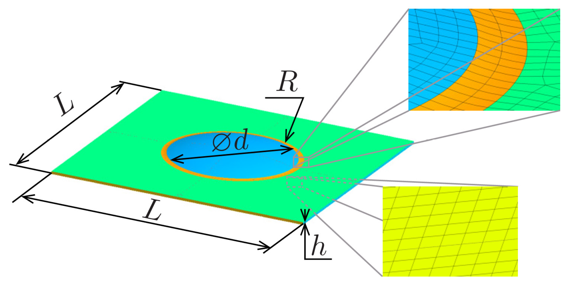
Consider a L by L sized rectangle-shaped oil film between the bearing housing and the journal. The journal has a ellipsoidal cap shaped dimple (see Figure 2). For simplicity, the bearing housing is assumed to slide with velocity V parallel to the positive x direction. Other parameters, such as ambient pressure, cavitation pressure, film thickness and dynamic viscosity are given in Table 1. In the finite element (FE) model, second-order quadrilateral elements were applied in a regular mesh to solve the pressure field. The geometry of the dimple, which was used only to determine the gap function h, was modeled with an irregular mesh (see Figure 2). At the side edges parallel with the velocity vector, the ambient pressure is given, while at the other two edges periodic boundary conditions were applied to the pressure of the lubricant.

4.1. Depth Analysis

In the depth analysis, the diameter of the micro-dimple was fixed at 0.25 mm, while the depth was varied from 0.001 mm to 0.03 mm. In this parameter study, no edge rounding was applied to the dimple.
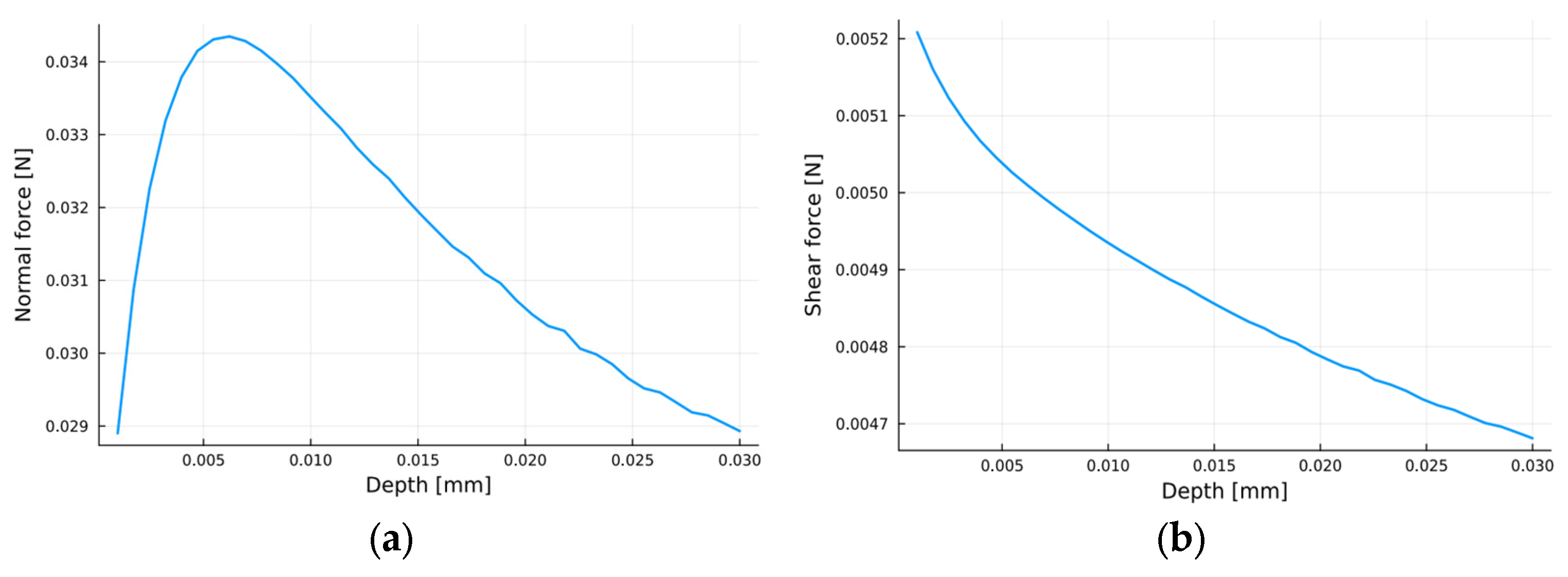
The results (see Figure 3) indicate that increasing the groove depth leads to a logarithmic decrease in friction force. However, the normal force initially increases, reaching a maximum around 0.0065 mm, after which it exhibits a monotonic decrease. Excessive dimple depth can therefore significantly reduce the load-carrying capacity of the lubricant, which may be disadvantageous in applications such as bearings.
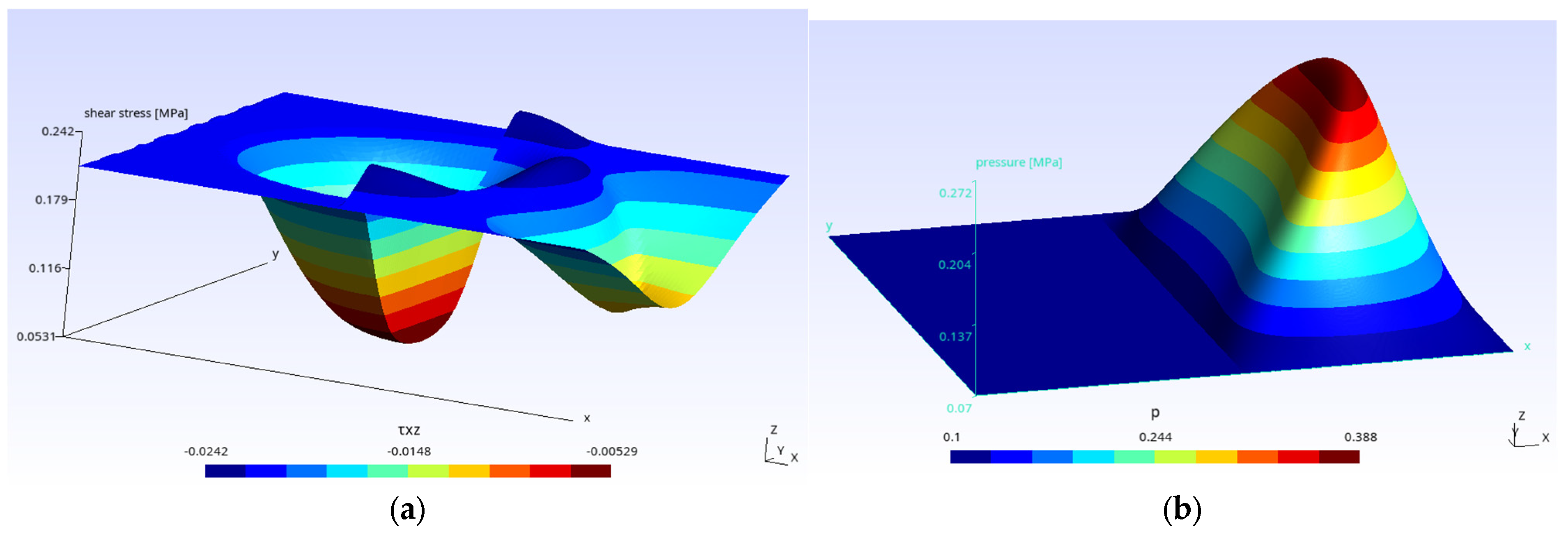
Figure 4 illustrates the stress fields corresponding to the maximum depth case (0.03 mm), where (a) shows the shear stress and (b) the fluid pressure. The location of the dimple is clearly visible from the stress fields (the lubricant flowing in the x-direction).

4.2. Fillet Radius Analysis

In this case, the diameter of the micro-dimple was again set to 0.25 mm, while the dimple depth was fixed at 0.015 mm. The fillet radius at the dimple’s edge was varied from 0.001 mm to 0.7 mm.
This time, the resulting curves for both the normal and tangential forces (see Figure 5) exhibited different behaviors. The normal force increases approximately linearly with the fillet radius, whereas the tangential force shows decreasing trend. Based on this observation, it appears advantageous to choose the largest permissible fillet radius defined by the geometry, as this minimizes frictional losses while maximizing the load-carrying capacity of the lubricant film.
Figure 6 presents the computed stress fields for the maximum fillet radius case (0.7 mm).

4.3. Comparison of Results

From Figure 3 and Figure 5, one can observe that doubling the initial dimple depth from 0.015 mm to 0.03 mm results in approximately a 3.09% reduction in frictional force. In contrast, maintaining the same dimple depth (0.015 mm) but increasing the fillet radius to 0.7 mm yields a greater reduction—about 5.15%.
Moreover, in the latter case, the normal force reaches approximately 0.037 N, compared to 0.029 N in the deeper dimple scenario—which is 27.59% higher. It is also important to consider that for large dimple depths, the Reynolds equation (which underpins the model) becomes less accurate. This limitation does not apply in the case of increased edge rounding, making it a more reliable and efficient design parameter.

5. Conclusions

These results represent only the initial findings of our project, yet they already indicate that further investigation into this phenomenon is well justified—potentially including dimples of different shapes as well. In future work, we intend to use our simulation tool to study how densely such micro-dimples can be arranged on a rectangular surface of a given area without adversely affecting each other’s performance.
Our ultimate goal is to determine the optimal micro-texture for a journal bearing operating under specific conditions, while also taking into account relevant design constraints. Finally, we aim to validate the simulation results through experimental measurements on the corresponding bearing configuration.

Author Contributions

Conceptualization, M.L. and B.P.; software, B.P.; writing—original draft preparation, M.L. and B.P.; writing—review and editing, M.L. and B.P.; visualization, B.P. All authors have read and agreed to the published version of the manuscript.

Funding

This article was published in the framework of the project “Production and Validation of Synthetic Fuels in Industry-University Collaboration”, project number “ÉZFF/956/2022-ITM_SZERZ”.

Institutional Review Board Statement

Not applicable.

Informed Consent Statement

Not applicable.

Data Availability Statement

The data presented in this study are available upon request from the corresponding author, as we would like to validate our simulation results with experiments ourselves.

Conflicts of Interest

The authors declare no conflicts of interest.

References

  1. Škurić, V.; Jasak, H.; Almqvist, A.; De Jaeger, P. Finite Area Algorithm for Thin Film Cavitation in OpenFOAM. Trans Motauto World 2019, 4, 3–7. [Google Scholar]
  2. Profito, F.J.; Giacopini, M.; Zachariadis, D.C.; Dini, D. A General Finite Volume Method for the Solution of the Reynolds Lubrication Equation with a Mass-Conserving Cavitation Model. Tribol. Lett. 2015, 60, 18. [Google Scholar] [CrossRef]
  3. Gravenkamp, H.; Pfeil, S.; Codina, R. Stabilized Finite Elements for the Solution of the Reynolds Equation Considering Cavitation. Comput. Methods Appl. Mech. Eng. 2024, 418, 116488. [Google Scholar] [CrossRef]
  4. Jarray, M.; Souchet, D.; Henry, Y.; Fatu, A. A Finite Element Solution of the Reynolds Equation of Lubrication with Film Discontinuities: Application to Helical Groove Seals. IOP Conf. Ser. Mater. Sci. Eng. 2017, 174, 012037. [Google Scholar] [CrossRef]
  5. Rom, M. Physics-Informed Neural Networks for the Reynolds Equation with Cavitation Modeling. Tribol. Int. 2023, 179, 108141. [Google Scholar] [CrossRef]
  6. Xi, Y.; Deng, J.; Li, Y. A New Method to Solve the Reynolds Equation Including Mass-Conserving Cavitation by Physics Informed Neural Networks (PINNs) with Both Soft and Hard Constraints. Friction 2024, 12, 1165–1175. [Google Scholar] [CrossRef]
  7. Li, X.; Song, Y.; Hao, Z.; Gu, C. Cavitation Mechanism of Oil-Film Bearing and Development of a New Gaseous Cavitation Model Based on Air Solubility. ASME J. Tribol. 2012, 134, 031701. [Google Scholar] [CrossRef]
  8. Bulut, D.; Bader, N.; Poll, G. Cavitation and Film Formation in Hydrodynamically Lubricated Parallel Sliders. Tribol. Int. 2021, 162, 107113. [Google Scholar] [CrossRef]
  9. Xu, W.; Tian, Y.; Li, K.; Zhang, M.; Yang, J. Reynolds Boundary Condition Realization in Journal Bearings: Location of Oil Film Rupture Boundary with Layering-Sliding Mesh Method. Tribol. Int. 2022, 165, 107330. [Google Scholar] [CrossRef]
  10. Laki, G.; Boros, L.; Nagy, A.L. Topography Pre-Treatment of Laser-Textured Surfaces for Friction Simulation in AVL Excite. Eng. Proc. 2024, 79, 95. [Google Scholar] [CrossRef]
  11. Grützmacher, P.G.; Rosenkranz, A.; Szurdak, A.; König, F.; Jacobs, G.; Hirt, G.; Mücklich, F. From Lab to Application—Improved Frictional Performance of Journal Bearings Induced by Single- and Multi-Scale Surface Patterns. Tribol. Int. 2018, 127, 500–508. [Google Scholar] [CrossRef]
  12. Vilhena, L.; Sedlaček, M.; Podgornik, B.; Rek, Z.; Žun, I. CFD Modeling of the Effect of Different Surface Texturing Geometries on the Frictional Behavior. Lubricants 2018, 6, 15. [Google Scholar] [CrossRef]
Figure 1. Geometry of the fluid film and cavitation.
Engproc 113 00002 g001
Figure 2. Geometry and FE mesh of the lubricant film. (green: flat surface, blue: dimple, orange: fillet).
Engproc 113 00002 g002
Figure 3. Forces as functions of dimple depth: (a) Normal force; (b) Shear (friction) force.
Engproc 113 00002 g003
Figure 4. Dimple without fillet: (a) Shear stress; (b) Pressure.
Engproc 113 00002 g004
Figure 5. Forces as functions of fillet radius: (a) Normal force; (b) Shear (friction) force.
Engproc 113 00002 g005
Figure 6. Dimple with fillet: (a) Shear stress; (b) Pressure.
Engproc 113 00002 g006
Table 1. Data for parameter study.
NameSymbolValue
side length of rectangle L 0.5   m m
film thickness h 0.005   m m
ambient pressure p 0 0.1   M P a
cavitation pressure p c a v 0.1   M P a
dynamic viscosity η 1.06 · 10 16   P a · s
velocity V 100   m m s
Disclaimer/Publisher’s Note: The statements, opinions and data contained in all publications are solely those of the individual author(s) and contributor(s) and not of MDPI and/or the editor(s). MDPI and/or the editor(s) disclaim responsibility for any injury to people or property resulting from any ideas, methods, instructions or products referred to in the content.