1. Introduction
Although internet-of-things-based surveillance systems, for example in air quality monitoring, have been developed, many of them make use of cloud platforms for data collection which make them both hardware-intensive and expensive [
1]. An alternative would be to record sensor data by manually scanning individual sensors using a portable electronic device. A simple and effective way of transmitting the data would be through the use of a dynamic quick-response (QR) code at each sensor. Such an approach would be cost-effective in terms of both production and operation and accessible due to its smartphone compatibility. A disadvantage is the requirement of an operator to manually scan each sensor [
2], but the approach may enable participatory citizen science projects [
3]. An electronic display could be used to implement a dynamic QR code that is able to convey real-time sensor data [
4]. While conventional displays can be both expensive and hardware-intensive due to their computational and electrical requirements, recently developed techniques, such as printed electronics and low-cost, flexible substrates, can be used to mitigate these problems [
5].
Flexible substrates have recently become popular due to properties that make them lightweight, flexible, and durable. Polyethylene terephthalate (PET) and Polyethylene naphthalate (PEN), which fall under the category of plastic foils, are some of the most commonly used substrates for flexible electronics. This is because they display remarkable resistance to solvents as well as a significant tolerance to heat, amongst many other useful properties [
5]. Owing to its robust and flexible nature, along with its capability to withstand high temperatures, Kapton, a type of polyimide film, scientifically referred to as poly (4,4′-oxydiphenylene-pyromellitimide) [
6], has, in recent times, also become a popular choice of substrate for flexible electronics [
7].
2. Materials and Methods
The chosen approach for implementing the dynamic QR code was through the use of LEDs, with each LED corresponding to a pixel of the version-one QR code. The designed multi-layer LED driver circuit was implemented on a PCB-designing software, EasyEDA. The Gerber file was generated from EasyEDA and converted to bitmap using the Ace translator software, version 8, in order to ensure that the file was in a format compatible with the Fujifilm Dimatix 2850 inkjet printer.
The top layer of the respective design was printed onto one side of a DuPont Kapton® 500B sheet using silver nanoparticle ink. Kapton® 500B is a black, homogeneous opaque polyimide film with a thickness of 125 microns (μm).
The pre-drying process involved placing the substrate in an oven at 50 °C for 50 min. Afterwards, the temperature was increased to 200 °C, which allowed the sintering process to occur, and this was confirmed by testing the traces using a multimeter to see if they were conductive.
For the bottom layer to be implemented accurately and to ensure that the vias would indeed connect the two layers at all necessary points, the alignment of the substrate, when placed on the inkjet printer, was a crucial factor. Since the Kapton substrate was non-transparent, four square-shaped fiducial markers were printed on each of the four corners of the top layer and subsequently cut out. In doing so, the fiducial markers would be visible from the bottom layer as well. The polyimide film (0.125 mm thickness) template on the LPKF ProtoLaser U4 laser system was used for this process.
The bottom layer had to be mirrored since the Dimatix inkjet printer was not designed to support multi-layer designs. A drop offset test was performed using the fiducial camera to ensure that the printer was calibrated. Using the fiducial camera, the top right fiducial was identified and used as the reference point for printing the bottom layer. The top two fiducials that were cut out earlier were used to perform translational and rotational alignment when printing the bottom layer.
Two nozzles were used when printing each respective layer. The same processes for the drying of the top layer were followed for the bottom layer. Both the top and bottom layers were then covered in self-adhesive films. This was done so that after the vias were cut using the LPKF ProtoLaser U4 laser system, LPKF ProConduct conductive paste could be applied with a squeegee over the entire surface while only plating the vias and not affecting the rest of the circuit. After the vias were cut out and plated, the self-adhesive film was removed from both sides of the PCB before being placed in the oven at 200 °C once again to cure the conductive paste.
3. Results
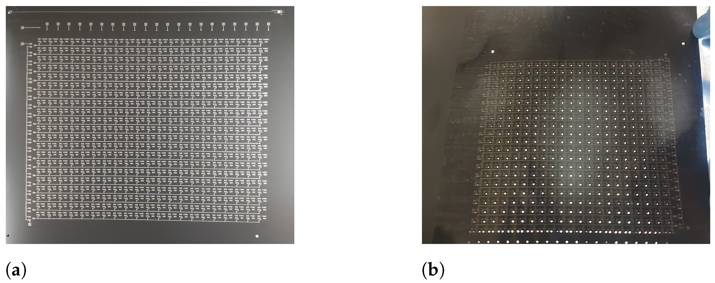
Figure 1a shows the top layer of the designed 14 × 12 cm, 21 × 21-pixel LED driver circuit that was successfully printed onto a sheet of Kapton, using the Dimatix inkjet printer in conjunction with silver nanoparticle ink, and subjected to the sintering process. The sintering process was deemed successful after testing the conductivity of the respective tracks using a multimeter.
Figure 1b shows light shining through the 441 laser-cut vias. Each via had a diameter of 0.31 mm and an annular ring that was 0.62 mm in diameter.
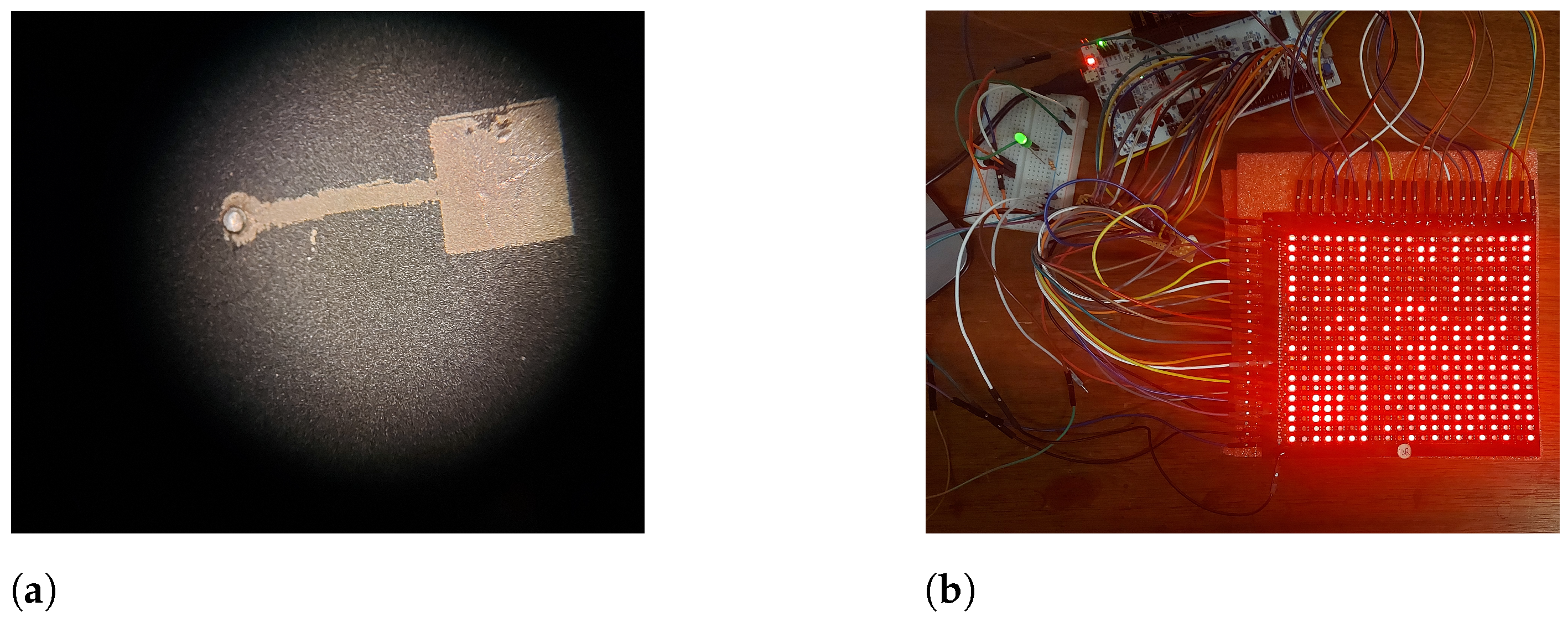
Figure 2a is a microscopic view of an individual plated via. Testing the conductivity between the two layers of the design indicated that all 441 vias successfully connected the top and bottom layers, indicating that the alignment was satisfactory across the entire circuit.
Figure 2b shows the final e-QR-code after assembly.
4. Discussion
A double-sided PCB was successfully implemented on a flexible substrate using inkjet printing. Inkjet-printed fiducial markers were used for alignment when cutting the vias. The same markers were then laser-cut in order to be visible from the bottom of an opaque substrate. In this way, accurate alignment was maintained throughout the manufacturing process. In addition to achieving correctly aligned vias, an effective method of plating the vias, using the LPKF ProConduct conductive paste, ensured that the top and bottom layers were properly connected. The successfully implemented multi-layer PCB was then populated with the corresponding SMD components, resulting in a flexible LED display module, which was further connected to a microcontroller that communicated the necessary data to display a dynamic version-one QR code that was capable of encoding real-time sensor values. This implementation can thus be considered a feasible alternative to wireless sensor networks, where the combination of high resource utilization and cost pose a significant challenge.
Multi-layer implementations can further be optimized by incorporating more digital additive manufacturing processes to the overall implementation, for example, printing the dielectric layer with digitally patterned via holes. In the context of this particular implementation, the use of a stencil for the solder paste dispensing could also be replaced with a more suitable digital printing process. These improvements will advance the manufacturing readiness level of the system.
Author Contributions
Conceptualization, T.-H.J.; methodology, A.E.R. and H.E.A.L.; writing—original draft preparation, A.E.R.; writing—review and editing, H.E.A.L. and T.-H.J.; supervision, T.-H.J. All authors have read and agreed to the published version of the manuscript.
Funding
This research was funded by the South African Department of Science and Innovation Nano and Micro Manufacturing Facility grant.
Institutional Review Board Statement
Not applicable.
Informed Consent Statement
Not applicable.
Data Availability Statement
The raw data supporting the conclusions of this article will be made available by the authors on request.
Conflicts of Interest
The authors declare no conflicts of interest. The funders had no role in the research or in the decision to publish the results.
References
- Liu, Z.; Wang, G.; Zhao, L.; Yang, G. Multi-Points Indoor Air Quality Monitoring Based on Internet of Things. IEEE Access 2021, 9, 70479–70492. [Google Scholar] [CrossRef]
- Ramalho, J.F.C.B.; António, L.C.F.; Correia, S.F.H.; Fu, L.S.; Pinho, A.S.; Brites, C.D.S.; Carlos, L.D.; André, P.S.; Ferreira, R.A.S. Luminescent QR Codes for Smart Labelling and Sensing. Opt. Laser Technol. 2018, 101, 304–311. [Google Scholar] [CrossRef]
- Mahajan, S.; Chung, M.K.; Martinez, J.; Olaya, Y.; Helbing, D.; Chen, L.J. Translating citizen-generated air quality data into evidence for shaping policy. Humanit. Soc. Sci. Commun. 2022, 9, 122. [Google Scholar] [CrossRef]
- Ramalho, J.F.C.B.; Correia, S.F.H.; Fu, L.; Dias, L.M.S.; Adão, P.; Mateus, P.; Ferreira, R.A.S.; André, P.S. Super Modules-Based Active QR Codes for Smart Trackability and IoT: A Responsive-Banknotes Case Study. Npj Flex. Electron. 2020, 4, 11. [Google Scholar] [CrossRef]
- Zardetto, V.; Brown, T.M.; Reale, A.; Di Carlo, A. Substrates for Flexible Electronics: A Practical Investigation on the Electrical, Film Flexibility, Optical, Temperature, and Solvent Resistance Properties. J. Polym. Sci. Part B Polym. Phys. 2011, 49, 638–648. [Google Scholar] [CrossRef]
- Bucciarelli, A.; Olivetti, E.; Adami, A.; Lorenzelli, L. Design of Experiment Rational Optimization of an Inkjet Deposition of Silver on Kapton. IEEE Sens. J. 2021, 21, 26304–26310. [Google Scholar] [CrossRef]
- Khaleel, H.R.; Al-Rizzo, H.M.; Rucker, D.G.; Mohan, S. A Compact Polyimide-Based UWB Antenna for Flexible Electronics. IEEE Antennas Wirel. Propag. Lett. 2012, 11, 564–567. [Google Scholar] [CrossRef]
| Disclaimer/Publisher’s Note: The statements, opinions and data contained in all publications are solely those of the individual author(s) and contributor(s) and not of MDPI and/or the editor(s). MDPI and/or the editor(s) disclaim responsibility for any injury to people or property resulting from any ideas, methods, instructions or products referred to in the content. |
© 2025 by the authors. Licensee MDPI, Basel, Switzerland. This article is an open access article distributed under the terms and conditions of the Creative Commons Attribution (CC BY) license (https://creativecommons.org/licenses/by/4.0/).


