Abstract
A parametric-based finite element model was developed to analyze the behavior of rotating disks made from functionally graded materials (FGMs) subjected to thermal loads. The model enabled the rapid determination of critical speeds to prevent slip and plastic deformation, while also enabling the analysis of disk performance under varying operational conditions, such as different rotational speeds, disk diameters, and material gradients. The model is a highly efficient tool for design engineers to assess stress and deformation in rotating disks and facilitates the optimization of FGM parameters, offering valuable support to FGM designers.
1. Introduction
Advanced structures with material properties that vary continuously in one or more directions offer significant potential for optimizing performance in demanding engineering applications. These materials, known as functionally graded materials (FGMs), enhance the functionality of components by tailoring properties such as elastic moduli. In vehicle gearboxes and high-speed spindles in machine tools, FGMs play a crucial role in improving durability, wear resistance, and overall performance. By optimizing material properties for specific operating conditions, FGMs offer substantial benefits for enhancing the reliability and efficiency of these components.
Researchers have developed analytical methods and numerical models to explore the applications of FGMs and assess their performance in engineering. Naghdabadi and Kordkheili [1] presented a finite element formulation for analyzing functionally graded plates and shells, focusing on thermoelastic behavior. The material properties, such as elastic modulus and thermal expansion, vary continuously through the thickness of the shell according to a power law formula. Bhowmick et al. [2] proposed a numerical method to investigate the stress and deformation states of rotating disks and analyze the effect of geometry and loading parameters on the stress and deformation statutes in various disk geometries. Bayat et al. [3] presented analytical and semi-analytical solutions to obtain the parabolic or hyperbolic convergent thickness profiles of disks. The results indicated that rotating FD disks with a concave or hyperbolic thickness profile are more efficient in high-temperature environments. Asghari and Ghafoori [4] presented a three-dimensional elasticity solution for functionally graded rotating disks, covering hollow and solid types. They demonstrated the importance of considering three-dimensional effects in the analysis of FG disks under centrifugal forces. Çallioğlu et al. [5] investigated the stress analysis of rotating disks made from FGMs. They examined how the elasticity modulus and density change radially based on a power law while keeping Poisson’s ratio constant.
Disks made of FGMs handle higher stresses than traditional homogeneous materials. Lin [6] used a unique governing equation derived from Whittaker’s functions to develop closed-form solutions for the mechanical behaviors of these disks. The FD disk with an exponentially varying profile and properties was investigated on the combinations of free and clamped surface boundary conditions. Shahzamanian et al. [7] conducted the thermal analysis of FG rotating disks made of metal and ceramic materials. Finite element methods as well as analytical approaches were adopted to examine how material properties affect thermal behavior in rotating systems. Fairclough and Batra [8] analytically examined finite torsional and extensional deformations of rubberlike FG Mooney–Rivlin cylinders. They assumed that the Mooney–Rivlin material module only varies in the radial direction of the deformation field. Hassan and Kurgan [9] examined the modeling of FGMs using the commercial finite element software ANSYS. They employed parametric design language (APDL) to implement various techniques, including the application of fictive thermal loads, stacking elements/layers, and utilizing user-defined fields. However, their research did not account for centrifugal loading. Burlayenko et al. [10] modeled functionally graded materials (FGMs) to analyze heat transfer and thermal stress using the commercial finite element software ABAQUS 6.12. They employed user material subroutines (UMAT) for mechanical properties and user-defined thermal material subroutines (UMATHT) for thermal properties to define position-dependent material characteristics within the finite element model. While they developed a theoretical model and integrated graded finite elements within ABAQUS for simulations of 2D problems, explicit examples or analyses were not provided for three-dimensional (3D) cases.
In this study, a parameter finite element method (PFEM) algorithm was developed to construct a 3D PFEM numerical procedure with a proportional partition method based on a cylindrical local coordinate system. The concept of similarity partition for isoparametric elements, along with the PFEM formulation, was used to automatically generate the number of elements layer-by-layer around the central point within the disk domain. The stiffness matrix and force vector, which include centrifugal and thermal loading in each layer, are only dependent on the radial distance from the center of the disk. As a result, the elasticity modulus and density were considered constant within each layer’s range. When the parameters of the FGM model changed, recalculating the layer stiffness matrix and force vector was unnecessary. Instead, the material constants associated with each layer were multiplied in the global stiffness matrix equation. The model solved for the displacements at each node and the von Mises stress at each Gauss point within the element. Three numerical examples were compared with the corresponding analytical solutions or FEM numerical solutions from commercial software ANSYS/ABAQUS to validate the 3-D PFEM algorithms and show the performance of the proposed method.
2. Parametric-Based Finite Element Formulation with FGM
In this study, the rotating FG disk was modeled with a modulus of elasticity distribution, as expressed in Equations (1) and (2), where the elasticity modulus E and mass density ρ vary as a function of the disk’s radius r. To model this, the radius was employed as a partitioning parameter within the cylindrical coordinate system. This approach is illustrated using two similar hexahedral elements, as shown in Figure 1.
where , which implies the scale ratio.
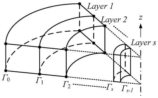
Figure 1.
Configuration of layer element mesh.
For elements in layer I, the local nodes i are numbered 1, 2, …, 8, following a consistent node numbering scheme to define the connectivity. denotes the local coordinate value of node i. All domains in the disk were meshed layer-by-layer. For the conversion between cylindrical and Cartesian coordinates, it was assumed that the reference plane of the former is the Cartesian xy-plane (with equation z = 0), and the cylindrical axis is the Cartesian z-axis. Then, the z-coordinate is the same in both systems, and the correspondence between cylindrical (r,θ,z) and global Cartesian(x,y,z) are the same as the polar coordinates.
x = r cos(θ)
y = r sin(θ)
z = z
From isoparametric representation, shape functions are used to express the coordinates of a point within element I in terms of the nodal coordinates. Therefore
The associated element stiffness matrix and nodal force load vector for a 3-D isoparametric element is then calculated using Equation (9).
where is the Young’s modulus of the element in layer number I, ν is the Poisson’s ratio, and the following matrices are included.
Since is a constant within each layer, it is factored out of the integration. As a result, the stiffness matrix becomes a function of radius r only. The force vector calculated for each layer of elements must account for the body force term resulting from the rotational effects, which is expressed as follows:
where .
The body force term is a function of radius r only. The force vector included the thermal loading term as follows:
where .
The nodal force load vector is shown as . The nodal force load vector for each layer of elements must account for both the rotational body force and thermal load, which is expressed solely as a function of the radial distance r. The stiffness matrix equation of the “ith element-layer” is expressed as
The global stiffness matrix equation is
by solving Equation (17), the nodal displacements can be obtained. Subsequently, we can return to each element to compute the stress components, as well as the von Mises stress.
3. Examples
Three examples were explored to demonstrate the validity of the results obtained using the proposed 3-D PFEM formulations. All related procedures used in this study were programmed in MATLAB languages. The first problem involving a solid rectangular column subjected to a gravitational field was used to verify the accuracy of the developed 3-D PFEM code, specifically assessing whether the body force term has been correctly incorporated. The second example introduced the 3-D IE-FEM coupled algorithm to solve a thin plate with near-edge holes, which were subjected to a concentrated load, and the third example demonstrated the ability of the IE-FEM method to solve multi-layered plate problems. For comparison, the results obtained from using analytical solutions or finite element solutions obtained from FEM commercial code ANSYS/ABAQUS were compared.
3.1. Example 1: Solid Rectangular Column Subjected to Gravitational Field
The first example problem involves a solid rectangular column with both a length and width of 50 m and a height of 500 m. Young’s modulus E = 2 GPa, Poisson’s ratio ν = 0.3, and density ρ = 7890 kg/m3. The column is subjected to a gravitational field with acceleration g = 9.8 m/s2 in the Z-direction. The boundary conditions are applied such that at location Z = L, with X = 0 and Y = 0. The model is fully fixed, while at Z = L and X, Y ≠ 0, only the Z-direction displacement is constrained. The theoretical solution for the displacement along the Z-direction was calculated using Equation (18). The finite element model utilized C3D20 higher-order hexahedral elements to enhance convergence accuracy. The geometric configuration and element layout are presented in Figure 2a. The validation results, presented in Figure 2b, indicate an average error of approximately 0.05%, thereby confirming the accuracy of the PFEM MATLAB code in simulating body forces.
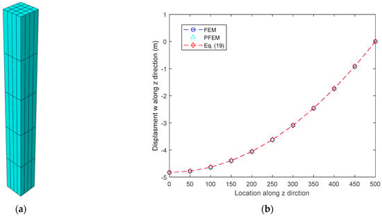
Figure 2.
(a) The FEM model of the rectangular column. (b) A comparison of the displacement w along the Z-direction is presented between the FEM, PFEM, and the exact solution.
3.2. Example 2: A Solid Cylinder Subjected to Thermal Load
In a solid cylinder with a circular cross-sectional area, the top and bottom surfaces are fixed and constrained, as depicted in Figure 3. The cylinder has a diameter of 5 μm and a length of 45 μm, and is subjected to a temperature change of 100 °C. The material properties are as follows: Young’s modulus E = 117 GPa, Poisson’s ratio ν = 0.34, and the coefficient of thermal expansion (CTE) = 16.4 × 10⁻⁶ /°C. Both FEM and PFEM were employed to solve this thermal load problem, with the cylinder partitioned into 1500 nodes and 1125 elements. Table 1 presents a comparison of the nodal displacements in the X and Y directions at locations A, B, and C, as shown in Figure 3. The results exhibit good agreement, validating the accuracy of the PFEM MATLAB code in simulating thermal loading.
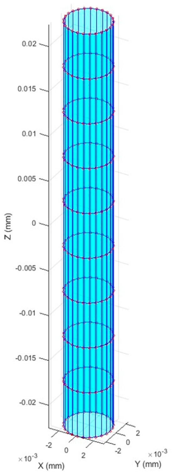
Figure 3.
Configuration of solid cylinder.

Table 1.
Comparison of nodal displacements at locations A, B, and C.
3.3. Example 3: Stress Analysis of Annular Rotating Disks Made of FGM Using PFEMs Subject to Thermal Loadings
Stress analysis was conducted on an annular rotating disk made of functionally graded materials (FGMs) utilizing the PFEM. The disk had inner and outer radii of a = 0.04 m and b = 0.14 m, respectively. The thickness of the disk varies radially, from the inner to the outer radius, according to Equations (19) and (20). Specifically, the inner thickness hi = 0.06 m, and the outer thickness ho = 0.01 m.
For the PFEM simulation, the disk was discretized into five radial layers, with each layer containing 12 elements along the circumference, as depicted in Figure 4. The material of the disk was assumed to be aluminum, with CTE α = 23.1 10−6 /°C, yield stress limit = 240 MPa, and melting temperature = 600 °C. The disk is modeled as a functionally graded material (FGM), with the elasticity modulus E and mass density ρ varying in the radial direction, as described by Equation (1). At the inner radius, the material properties were = 71 GPa and = 2700 kg/m3, while at the outer radius, they were = 150 GPa and = 5400 kg/m3. The disk was assumed to rotate with angular velocity . The inside boundary of the disk was assumed to be fully fixed (mounted on a rigid shaft), while the outside boundary is traction-free.
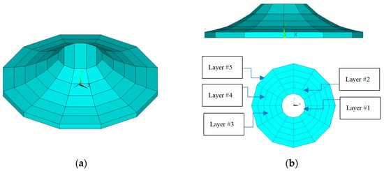
Figure 4.
(a) The PFEM model of FG disk; (b) the side and top view of the PFEM model.
Figure 5 illustrates the comparison of the maximum von Mises stress inside the disk from the PFEM solution. The maximum von Mises stress from the PFEM solution at the FD disk rotating with angular velocity w = 1000, 2000, and 3000 rad/s and temperature ranged from 25 to 100 °C. Under certain critical conditions, such as at an angular velocity of 2000 rad/s, a working temperature of 100 °C, an angular velocity of 3000 rad/s, and a working temperature of 75 °C, the maximum von Mises stress exceeded the aluminum yield stress limit. Under these conditions, plastic deformation occurs, particularly near the shaft region of the disk. Furthermore, residual stress accumulates after each operation.
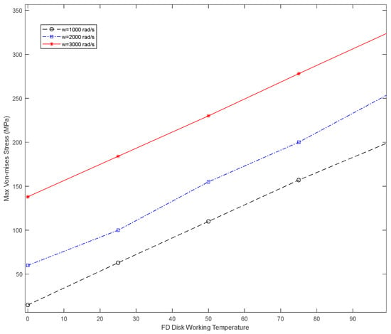
Figure 5.
Maximum von Mises stress from PFEM solution at FD disk rotating with angular velocity =1000 rad/s, 2000 rad/s, and 3000 rad/s.
4. Conclusions
The concept of similarity partition for isoparametric elements, along with the PFEM formulation, was used to automatically generate the number of elements layer-by-layer around the central point within the disk domain. The stiffness matrix and force vector account for centrifugal and thermal loading in each layer and depend solely on the radial distance from the disk’s center. Consequently, the elasticity modulus and density are treated as constant within the range of each layer. Even with a change in the parameters of the FGM model, the stiffness matrix and force vector for each layer do not need to be recalculated. Instead, the material constants for each layer are directly multiplied and incorporated into the global stiffness matrix equation. This approach enables the system to be solved efficiently and accurately for the displacements at each node and the von Mises stress at each Gauss point within the element. To validate the PFEM algorithms and assess the performance of the proposed method, three numerical examples are presented and compared with the corresponding analytical solutions or FEM results obtained from commercial software such as ANSYS/ABAQUS.
Author Contributions
Conceptualization, C.-J.L. and W.-F.L.; methodology, W.-F.L.; software, C.-J.L.; validation, C.-J.L.; formal analysis, C.-J.L.; investigation, C.-J.L.; resources, C.-J.L.; data curation, C.-J.L.; writing—original draft preparation, C.-J.L.; writing—review and editing, C.-J.L. and W.-F.L.; visualization, C.-J.L.; supervision, C.-J.L.; project administration, C.-J.L.; funding acquisition, W.-F.L. All authors have read and agreed to the published version of the manuscript.
Funding
This research was funded by Special Fund Category: Guangdong-Hong Kong-Macao Greater Bay Area International Science and Technology Innovation Center Construction, and Program Category: Guangdong-Taiwan Science and Technology Cooperation. grant number 2024A0505050046. And The APC was funded by Engineering Proceedings.
Data Availability Statement
The original contributions presented in this study are included in the article. Further inquiries can be directed to the corresponding author(s).
Conflicts of Interest
The authors declare no conflict of interest.
References
- Naghdabadi, R.; Kordkheili, S.A.H. A finite element formulation for analysis of functionally graded plates and shells. Arch. Appl. Mech. 2005, 74, 375–386. [Google Scholar] [CrossRef]
- Bhowmick, S.; Misra, D.; Saha, K.N. Approximate solution of limit angular speed for externally loaded rotating solid disk. Int. J. Mech. Sci. 2008, 50, 163–174. [Google Scholar] [CrossRef]
- Bayat, M.; Saleem, M.; Sahari, B.B.; Hamouda, A.M.S.; Mahdi, E. Analysis of functionally graded rotating disks with variable thickness. Mech. Res. Commun. 2008, 35, 283–309. [Google Scholar] [CrossRef]
- Asghari, M.; Ghafoori, E. A three-dimensional elasticity solution for functionally graded rotating disks. Compos. Struct. 2010, 92, 1092–1099. [Google Scholar] [CrossRef]
- Çallioğlu, H.; Bektas, N.B.; Sayer, M. Stress analysis of functionally graded rotating discs: Analytical and numerical solutions. Acta Mech. Sin. 2011, 27, 950–955. [Google Scholar] [CrossRef]
- Lin, W.F. Elastic Analysis for Rotating Functionally Graded Annular Disk with Exponentially-Varying Profile and Properties. Math. Probl. Eng. 2020, 2020, 2165804. [Google Scholar] [CrossRef]
- Shahzamanian, M.M.; Shahrjerdi, A.; Sahari, B.B.; Wu, P.D. Steady-State Thermal Analysis of Functionally Graded Rotating Disks Using Finite Element and Analytical Methods. Materials 2022, 15, 5548. [Google Scholar] [CrossRef]
- Fairclough, K.A.; Batra, R.C. Torsion and Extension of Functionally Graded Mooney–Rivlin Cylinders. J. Elast. 2024, 157, 4. [Google Scholar] [CrossRef]
- Hassan, A.H.A.; Kurgan, N. Modeling Functionally Graded Materials in ANSYS APDL. Res. Sq. 2022; preprint. [Google Scholar] [CrossRef]
- Burlayenko, V.N.; Altenbach, H.; Sadowski, T.; Dimitrova, S.D.; Bhaskar, A. Modelling functionally graded materials in heat transfer and thermal stress analysis by means of graded finite elements. Appl. Math. Model. 2017, 45, 422–438. [Google Scholar] [CrossRef]
Disclaimer/Publisher’s Note: The statements, opinions and data contained in all publications are solely those of the individual author(s) and contributor(s) and not of MDPI and/or the editor(s). MDPI and/or the editor(s) disclaim responsibility for any injury to people or property resulting from any ideas, methods, instructions or products referred to in the content. |
© 2025 by the authors. Licensee MDPI, Basel, Switzerland. This article is an open access article distributed under the terms and conditions of the Creative Commons Attribution (CC BY) license (https://creativecommons.org/licenses/by/4.0/).