1. Introduction
Today, forklifts are an indispensable part of operations in every industrial enterprise, logistics center, and/or hub for handling and manipulating cargo [
1].
One of the main systems in forklifts that assists with cargo handling is the hydraulic system. Its purpose is to generate sufficient power for cargo processing through various auxiliary functions such as lifting, lowering, rotating, lateral shifting, extending, and retracting. The hydraulic system must be capable of providing enough power to perform these functions simultaneously when required. Additionally, while carrying out these functions, the hydraulic system must ensure smooth and rapid movement [
2].
Forklifts and electric forklifts primarily use two types of hydraulic systems: open and closed [
2].
The open hydraulic system operates with a circulation process in which the pump draws fluid from the reservoir, and at the end of the working cycle, the fluid returns to the reservoir. These systems typically use fixed-displacement pumps as the main source of flow and pressure. The maximum pressure in this system is regulated by a pressure-relief valve, while the working pressure depends on the resistance exerted on the fluid under different loads. When the system pressure exceeds the limit set by the relief valve, the flow is redirected through the valve back to the reservoir [
2].
In a closed hydraulic system, the fluid circulates in a closed loop between the pump and the actuators without returning to a reservoir after each cycle. Instead, the pump directly controls the flow direction and pressure, allowing for more precise and efficient operation. Since the hydraulic fluid does not constantly return to a reservoir, closed systems require more effective cooling and filtration solutions to ensure fluid quality and prevent overheating. They are commonly used in applications requiring high efficiency, precise control, and compact designs, such as hydrostatic transmissions in forklifts, construction equipment, and industrial machinery.
In the design of hydraulic systems, the use of specialized software has become increasingly common. This software enables the creation of simulations based on existing models to optimize system performance and identify reliable solutions to emerging issues. The components used in these systems are typically selected from existing catalogs, ensuring that their characteristics and specifications are accurately accounted for. Once the simulations are completed, the data obtained from system operation is analyzed [
3].
Performing data analysis in a digital environment, particularly when evaluating the impact of modifications to specific system elements, enhances the efficiency of design engineers [
2]. Additionally, studying the various components used in hydraulic systems facilitates the proper selection of components for each specific application [
4].
Considering the information above, the main purpose of the article is to present a strategy for optimal control in a forklift hydraulic system with open center.
2. Materials and Methods
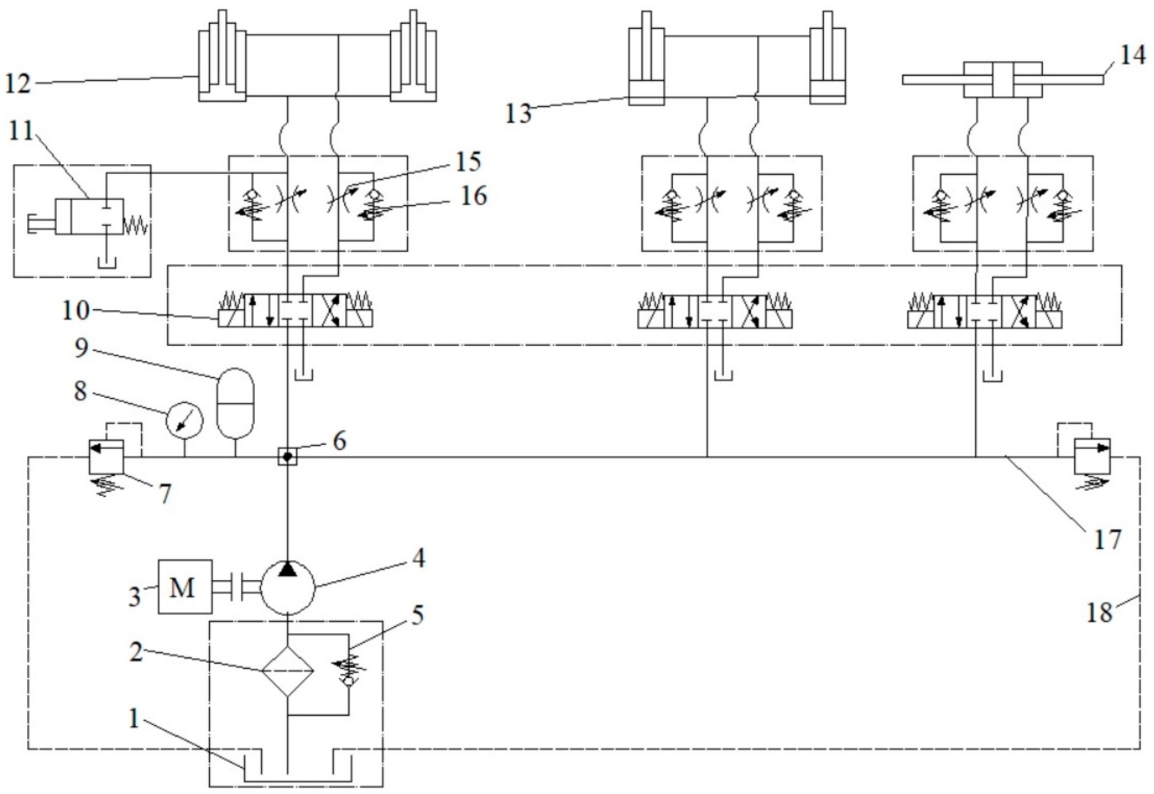
The functional structure of the hydraulic system of a forklift (“Balkancar Record” Co, Plovdiv, Bulgaria) includes an external gear hydraulic pump driven by an internal combustion engine, hydraulic distributors, power cylinders, hydro-accumulators, filters, relief valves, pipelines, an emergency lowering button, and other components ensuring proper operation.
The hydraulic system shown in
Figure 1 is an “open-center” type, including an emergency lowering button, safety-overflow valves, and hydro-accumulators. The gear pump used in the system has external meshing and a constant flow rate. The hydraulic distributors are 4/3 valves with a tandem center, meaning that when the plunger is in the neutral position, the pump is connected to the reservoir. The hydraulic resistances (throttles) are adjustable, meaning they have a variable cross-section. Check valves with variable cross-sections are also selected. The safety-overflow valves are adjustable. The hydraulic system is powered by the forklift’s internal combustion engine.
The hydraulic cylinders are double-acting and include telescopic plunger cylinders, piston cylinders with single-sided and double-sided piston rods.
The selection of the hydraulic pump is based on catalog specifications, with some characteristics presented in
Table 1. The choice of a hydraulic pump depends on the input power of the pump shaft, i.e., the selection of the internal combustion engine driving the pump, the pressure generated at the pump outlet, i.e., the load to be lifted by the power cylinders, and the generated flow rate, i.e., the filling speed of the power cylinders.
The power cylinders are selected as telescopic cylinders with a maximum lifting height of 10 m. Single-piston power cylinders are used for mast tilting, while a dual-piston power cylinder is used for the lateral movement of the forks.
The hydraulic systems of high-lift forklifts are typically designed to operate at a nominal high working pressure of up to 25 MPa, with a maximum load capacity of 3000 kg. Other design requirements include a lifting and lowering speed with or without load of 33 ± 3 cm/s, the ability to tilt the forks and move them laterally, a maximum noise level of 60 dB, an operating temperature range from −20 °C to 80 °C, and fluid cleanliness in accordance with ISO 4406 [
1,
2,
3,
4,
5].
Pumps are selected based on two main parameters: flow rate and pressure—that is, the amount of fluid passing through a given cross-section per unit of time, and the energy required to overcome the resistance of the elements in the system. The greater the losses caused by the fluid passing through pipes, fittings, and other components, the higher the required pressure. The pump is selected according to the required flow rate and pressure, with the system resistance determining the pressure that needs to be provided. Typically, as the flow rate increases, the pump head decreases.
For a hydraulic pump to function properly, it must meet the following requirements: high flow rate, minimal torque, and minimal driving power. These operational requirements are determined by the pump’s characteristics, including displacement, nominal pressure, and nominal rotational speed.
The flow rate of the hydraulic pump is determined by the following formula [
6,
7]:
where
n is the rotation speed, min
−1;
V—flow rate per one revolution of the pump shaft cm
3/rev;
ηv—volumetric efficiency is determined by the magnitude of fluid flow losses in the system. It is typically assumed to be 0.98.
The required torque to drive the external gear hydraulic pump is calculated using the formula [
6,
7]:
where
ηm is the mechanical efficiency.
The required power to drive the external gear hydraulic pump is calculated using the formula [
6,
7]:
where
p is the outlet pressure of the pump, assumed to be constant;
ηt =
ηv·
ηm—total efficiency.
The hydraulic system of the forklift was designed using the software product Automation Studio V4.2—specialized software for computer simulations in this field. Automation Studio serves as a platform for constructing a virtual hydraulic system with various components, allowing for testing and adjustment of operating parameters. This capability significantly reduces time and costs associated with system development. Automation Studio is certified under ISO 9001:2015, ensuring that customer expectations for high-quality and reliable solutions are fully met, while also enhancing end-user satisfaction [
8,
9].
3. Results and Discussion
The proper functioning of the hydraulic system includes lifting, shifting, and tilting loads using the power cylinders shown in
Figure 2. The hydraulic system operates with two circuits and a common pump driven by an internal combustion engine. The first part of the system is dedicated solely to lifting and lowering loads, with no pressure drop observed across the hydraulic distributors and relief valves. The selected hydraulic distributors do not interfere with the safety-overflow valves, allowing excess fluid to return to the reservoir. Another important feature is the presence of an emergency button in case of failure of the hydraulic distributor, power cylinder, or safety-overflow valve. When the emergency button is activated, the flow to the power cylinders is stopped, and the excess fluid is redirected to the reservoir.
Improper design, operation, or maintenance of the hydraulic system can lead to high fluid temperatures, which may cause damage and prolonged downtime. As the fluid temperature increases, its viscosity decreases. Specific viscosity levels are required to lubricate the internal friction surfaces of components by forming an oil film between them. If the viscosity is too low, this oil film becomes excessively thin, leading to dry or semi-dry friction between surfaces.
Maintaining filters is another crucial aspect of the hydraulic system operation, as it can result in a pressure drop. The pressure drop depends on the filtration surface area, fluid temperature, and viscosity.
Reservoirs play a key role in the proper functioning of hydraulic systems, and their maintenance involves checking the fluid level, monitoring moisture levels, and inspecting the airflow around the reservoir. If additional cooling of the hydraulic fluid is not possible, modifications to the reservoir design may be required, including ribbing of the walls and other heat dissipation methods. Since hydraulic systems operate with vented reservoirs, moisture from the humid air adheres to the reservoir walls, leading to rust formation. Vibrations during hydraulic system operation dislodge rust particles into the fluid, which are then drawn into the pump during operation.
The selection of the hydraulic pump is based on the data in
Table 1 and the Formulae (1)–(3). The minimum rotational speed is set at 700 min
−1 for all pumps in the study, while the minimum outlet pressure is 160 bar for all pumps.
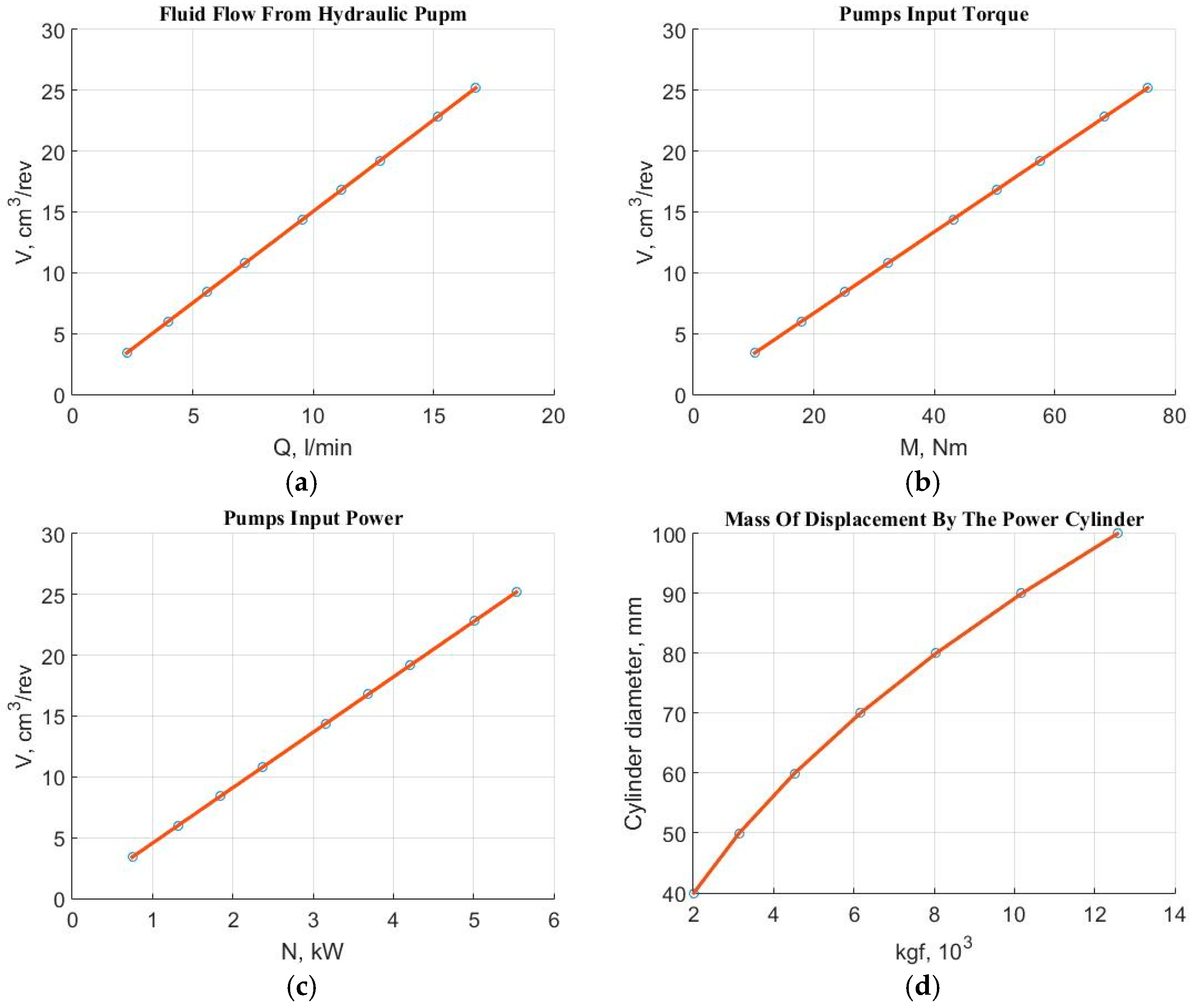
Using Equations (1)–(3), graphical representations are derived for the pump’s flow rate, required power, and driving torque as functions of the displacement volume, as well as for the mass lifted by the power cylinders as a function of the piston diameter. As the displacement volume, nominal pressure, and shaft speed of the pump increase, the flow rate, required power, and required torque also increase. This means that in order to meet the requirements for lifting heavier loads, an internal combustion engine with higher power characteristics is needed, along with an appropriate resizing of the hydraulic system structure.
As shown in
Figure 3a [
10], increasing the displacement volume at constant rotational speed leads to an increase in flow rate and, consequently, a higher filling speed of the telescopic lifting (power) cylinders. Depending on the hydraulic system layout, an internal combustion engine should be selected to supply power to the hydraulic system while simultaneously powering the transmission for vehicle movement [
11,
12].
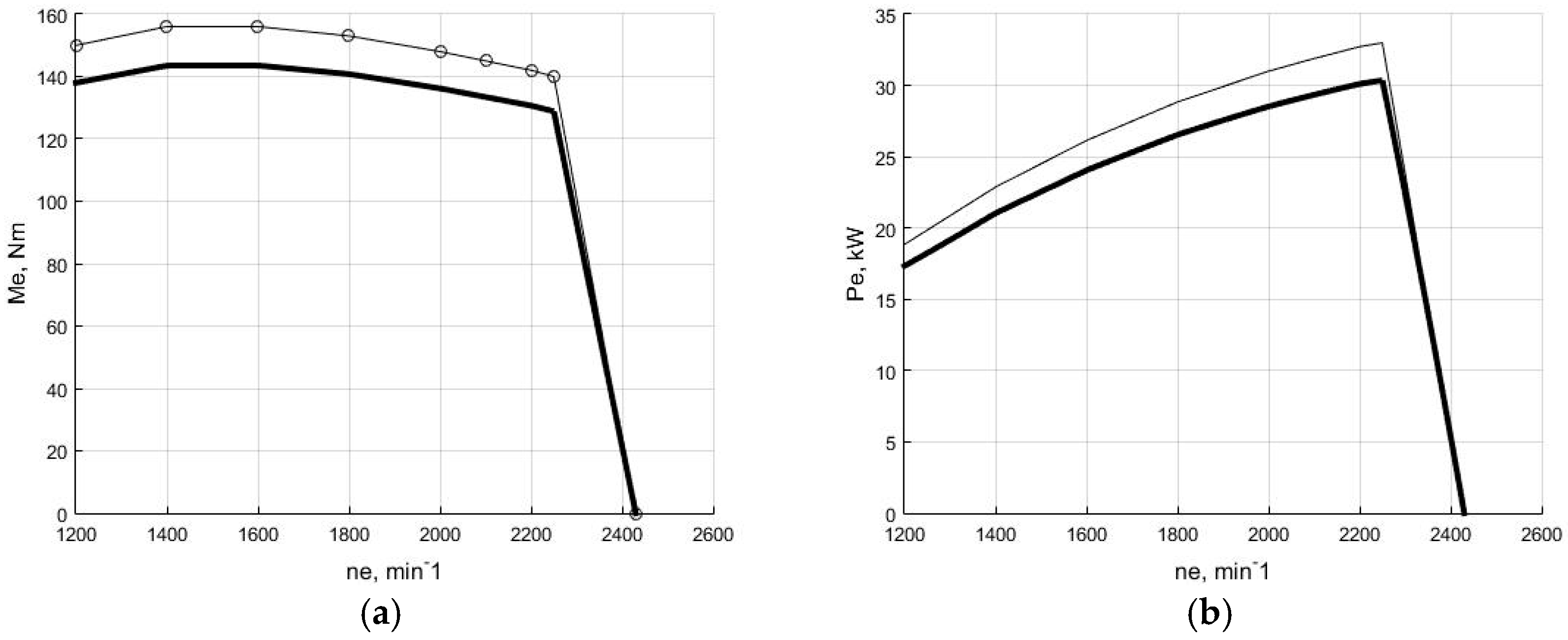
As shown in
Figure 4, the forklift engine’s torque and power characteristics [
11] indicate a maximum torque of 140 Nm, which is enough to justify the selected gear pumps listed in
Figure 3b.
4. Conclusions
This study presents the design and analysis of an open-center hydraulic system for forklift applications, integrating external gear pumps, safety-overflow valves, and an emergency lowering mechanism [
13]. The system was dimensioned using catalog data and validated through simulations. Unlike other hydraulic system designs [
2], the proposed solution is clear and simple, with the option of an upgrade to electric control.
Key parameters—including flow rate, input torque, and power—were evaluated in relation to pump displacement and engine characteristics, ensuring compatibility with high-load operational requirements. The proposed configuration supports lifting, tilting, and lateral movement with appropriate safety and fault-response features.
Thermal effects, filtration efficiency, and fluid maintenance were also addressed to ensure system reliability and longevity. The methodology combines theoretical modeling with simulation-based validation and provides a practical framework for the design of efficient and safe hydraulic systems in material handling equipment [
14].


