1. Introduction
The Axial Flux Permanent Magnet (AFPM) synchronous generator (AFPMSG) has been increasingly researched and utilized in recent times. The axial flux structure requires less electrical steel, resulting in a higher torque-to-weight ratio. The AFPM machine has a compact size and a short frame compared to traditional electrical machines (such as radial flux permanent magnet machines-RFPM), making it suitable for applications with space constraints in the axial direction, such as wheel-integrated motors of electric vehicles and vertical axis wind turbines [
1,
2].
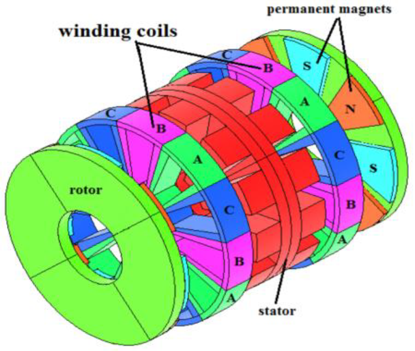
Structurally, the AFPM machine has various shapes and configurations, including single-sided, double-sided, and multi-rotor/multi-stator arrangements. These designs may incorporate slotted or slotless armatures, as well as cored or coreless armature constructions. For double-sided and multi-rotor variants, the machine architecture may feature either inner rotor or outer rotor configurations [
1]. The machine’s structure used in this paper is the inner single-stator, external double-rotor type with a slotted stator as described in
Figure 1 and
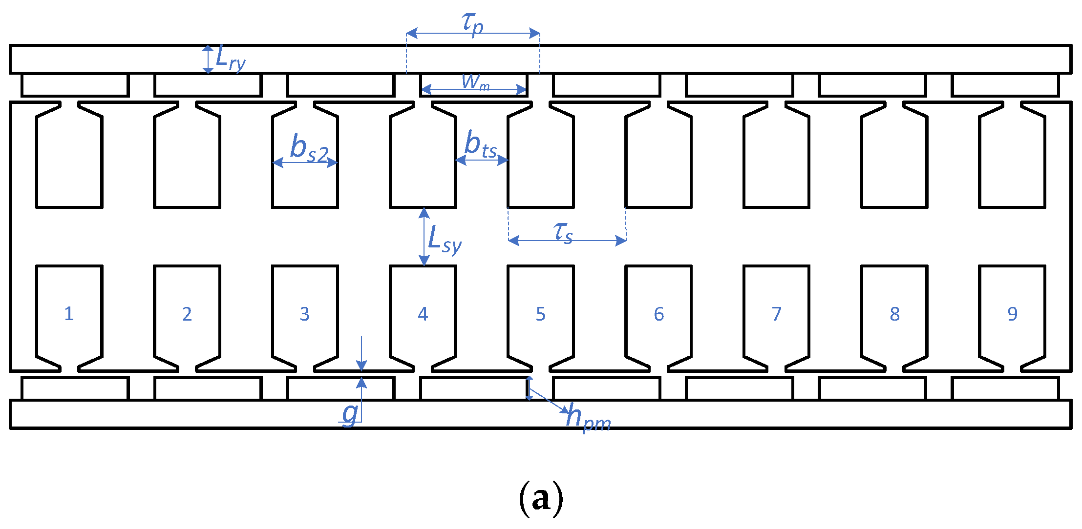
Figure 2 [
1].
The AFPM machine with a single-stator, double-rotor structure has key advantages, such as reducing iron losses and increasing power density. Especially, using this configuration, cooling for the generator is easier because the rotor has permanent magnets mounted on the rotating surface, acting as a fan for cooling the stator [
2,
3]. However, this machine also presents some drawbacks, including high expense for materials and manufacturing concerning the use of permanent magnets and the fabrication of stator core laminations [
2]. In previous discussions on AFPM machines, other authors have shared insights related to machine modeling, general analysis and design, and the relationship between slot-pole combinations and winding factors. This paper aims to provide a more comprehensive design process for the AFPM generators using the effective analytical model and equivalent finite element method (FEM) model, including magnetic saturation and rotor-linear motion, to refine the initial computational results. In-depth, a precise model for AFPMSG must be implemented in a 3D-transient FEM including magnetic saturation, but it is very time-consuming. Therefore, in this paper, an equivalent 2D-FEM model including rotor linear motion, instead of a 3D-FEM model, is proposed in trade-off between computational accuracy and time for the refined design in the final design step of the AFPMSG.
This paper presents the design of a 1.35 kW axial-flux permanent magnet synchronous generator with outer double-rotor and double-layer concentrated windings for a vertical-axis wind turbine application. First, the basic dimensions of the generator are determined using sizing analytical equations. Next, key electromagnetic parameters, including electromotive force, electrical current, electromagnetic torque, power losses, and efficiency, are analytically computed. If the initial results fail to meet the specified requirements, the design is iteratively refined using the analytical model. Finally, FEM simulations are employed to optimize the preliminary design. The influence of the slotting effect on an AFPM machine’s performance, such as air gap flux density, voltage, and cogging torque, is also investigated.
2. Input Parameters and Design Flow Chart
2.1. Input Parameters
The axial flux generator in this paper is designed for application in a VAWT operating at low speed. The initial rated parameters, including rated power, rated voltage, rated speed, and power factor, are presented in
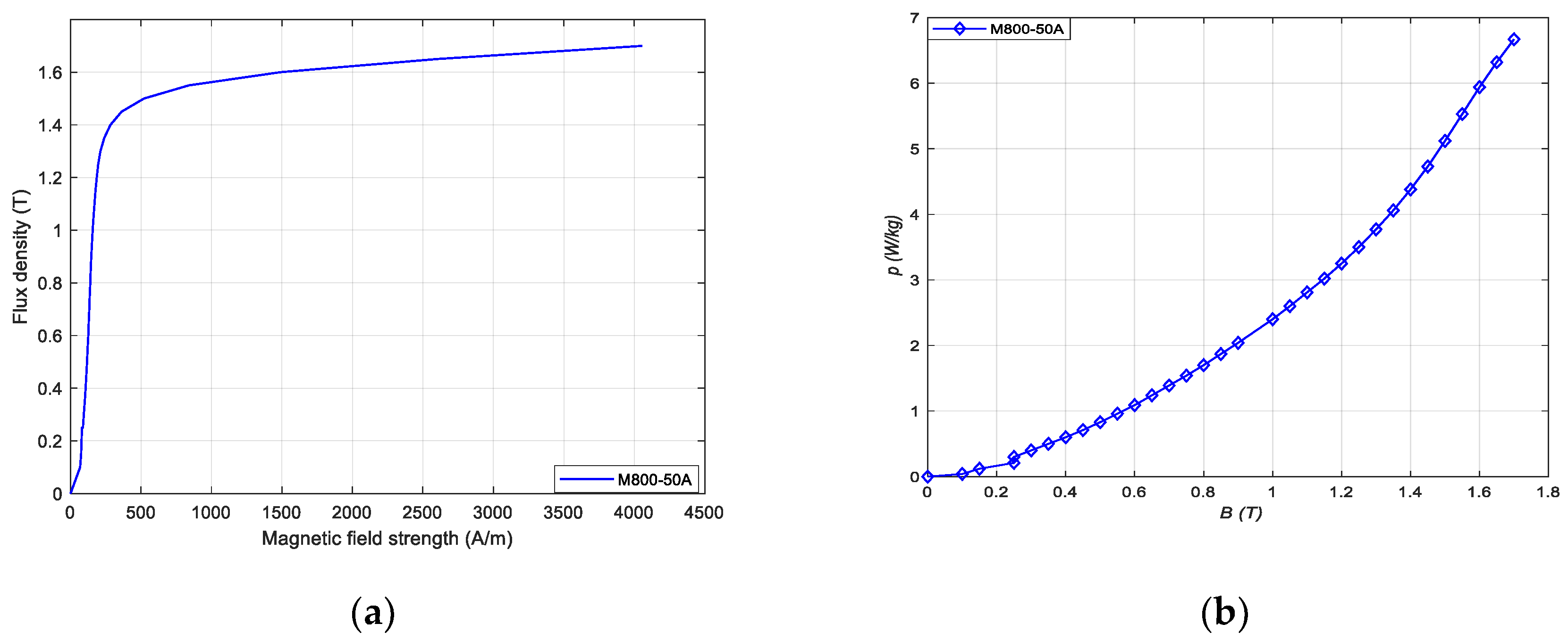
Table 1. In this design, the type of steel used is M800-50A, with its magnetization curve shown in
Figure 3.
2.1.1. Permanent Magnet Material
The most commonly used permanent magnet materials for PM machines include ferrites, bonded neodymium-iron-boron (NdFeB), sintered NdFeB, and bonded or sintered samarium-cobalt (SmCo). For this design, sintered NdFeB magnets (N40) from ARNOLD
® [
4] were selected. This material is preferred due to its high energy density, high coercivity force, and maximum operating temperature of up to 180 °C. However, its high electrical conductivity contributes to significant eddy current losses in the magnets.
It should be noted that the remanent flux density
Br exhibits a negative temperature coefficient, decreasing with rising temperature. This relationship is characterized by the reversible temperature coefficient of
Br. The remanent flux density at a given temperature
T (in °C) can be expressed as follows [
5]:
where
Br(20) is the value of
Br at ambient temperature.
2.1.2. Lamination Steel
The stator core is stacked by iron laminations with a silicon percentage from 2% to 6% to minimize eddy current losses. The material is characterized by a small hysteresis loop, high permeability, and low coercivity. The silicon content plays an important role in the material’s electromagnetic properties. A higher silicon content increases electrical resistance, thereby reducing eddy current losses, but it also lowers the magnetic permeability. Thinner steel laminations reduce iron losses; however, manufacturing costs increase.
2.2. Design Flow Chart
The overall design flowchart is illustrated in
Figure 4. The process begins with the initial parameters specified in
Table 1. Analytical equations are then employed during the preliminary design stage to estimate key performance metrics such as output power, losses, and efficiency. If the analytical results satisfy the design requirements, the process proceeds to the refinement stage. In this stage, a time-stepping finite element method (FEM) model is utilized to enhance the accuracy of the design by incorporating rotor motion and allowing geometric adjustments. The refinement begins with the dimensions obtained from the preliminary analysis, and through iterative simulations, the design is optimized to meet the desired performance objectives.
3. Main Structural and Winding Design Aspects of an AFPMSG
3.1. Main Dimensions
The main dimensions of the AFPMSG machine are determined based on parameters such as electrical loading (
Am), the number of turns per phase on the stator (
N1), the armature phase current of the stator winding (
Ia), the maximum magnetic flux density in the air gap (
B1g,max), the winding factor (
kw), and the ratio of inner to outer diameter (
kd). The stator outer diameter of a AFPMSG can be calculated as shown in the following Equation (2) [
2,
6]:
the ratio
kD is the defined as follows:
where
ke is the induced voltage factor.
For axial flux permanent magnet machines, the diameter ratio (
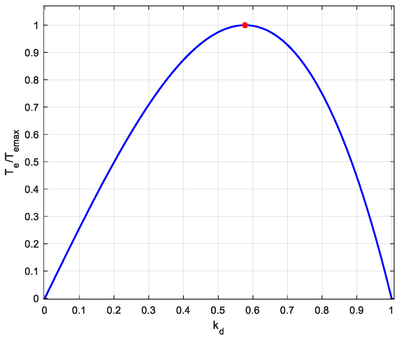
kd) is a critical design parameter influencing torque production. The machine’s electromagnetic torque generation capacity is dependent on the value of
kd [
7]. The optimum diameter ratio for the machine is shown in
Figure 5. In this design, choose the diameter ratio as
kd = 0.6.
In the initial design, the air gap width is selected as
g = 1.2 mm, this value largely depends on the manufacturing technology. The electromagnetic torque and voltage of a machine are reduced by the disturbed flux density in the air gap and harmonics due to slotting effect. The Carter factor taken into account is calculated following Equation (5), [
8]:
The magnetic flux per pole is determined by (6), based on the number of pole pairs, amplitude of fundamental air-gap flux density, and the machine’s inner and outer diameters [
2,
9].
The preliminary design parameters of the machine, including the dimensions of the stator frame, rotor, and other key specifications are summarized in
Table 2.
The relationship between the average air-gap flux density generated by the magnets and the remanent flux density of the magnets can be expressed as follows [
8,
10]:
where
hpm is the thickness of the magnet,
µrm is relative permeability of magnet and
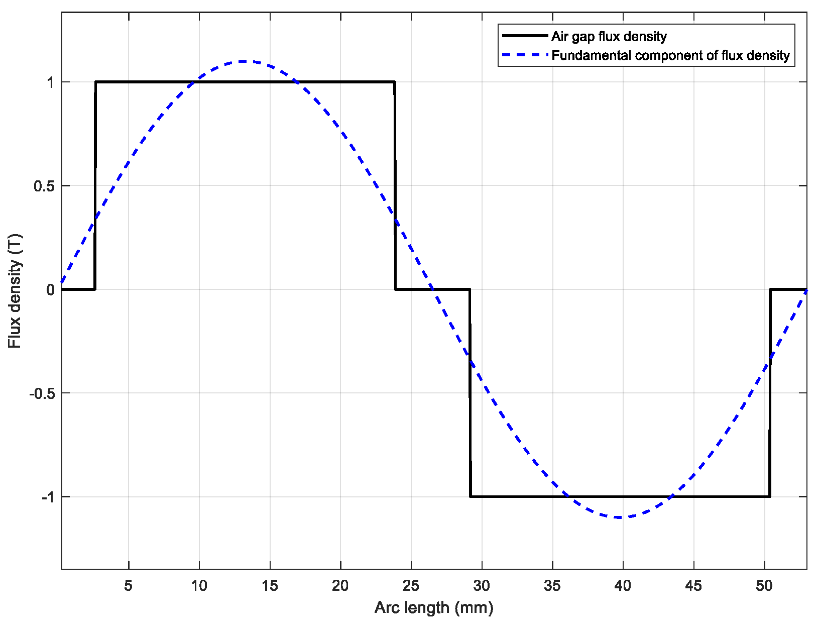
geff is the effective air-gap. The air-gap flux density at positions directly opposite the magnets is approximately modeled as a rectangular waveform, as depicted in
Figure 6.
3.2. Winding Calculation
3.2.1. Winding Factor Formula
In this design, the AFPM machine uses a double-layer concentrated winding to reduce higher-order harmonics in the electromotive force. The advantage of concentrated windings is shorter coil length and a simpler structure. Furthermore, with a high number of poles, concentrated windings have an appropriate winding factor and can help reduce copper losses [
2,
3]. For double-layer 3-phase windings, each phase of the winding will occupy
Qs/3 slots. The fundamental winding factor
kw is calculated using the following expression:
where
z is the number of teeth in a symmetrical sector,
z is found from [
11].
where
gcd represents the greatest common divisor of the total number of slots and poles,
z is an integer number.
Electrical angle
θm corresponding to a tooth pitch is defined as follows:
3.2.2. The Impact of Combination of Number of Slots and Poles
An essential goal in the design of electric machines with concentrated windings is to obtain the highest possible winding factor [
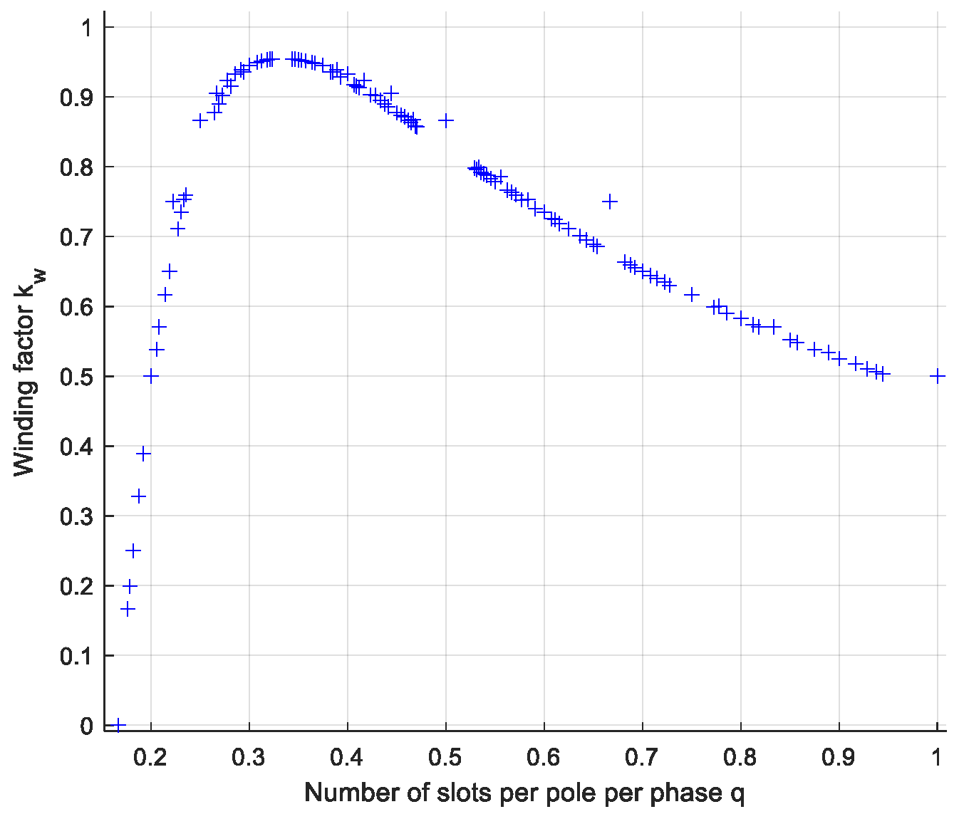
12]. It is evident that a higher fundamental winding factor results in a higher fundamental electromotive force. From (8), the dependence of the winding factor as a function of
q can be determined.
From
Figure 7, it can be seen that the range of
q for the winding factor
kw to achieve a high value is between ¼ and ½. The winding factor values are presented in
Table 3 for different slot-pole combinations. In
Table 3, the feasible combinations of the winding factor are presented, with the value of
q (the number of slots per pole per phase) ranging from ¼ to ½. The shaded areas represent combinations that are eliminated based on general design principles, including the requirement that
z must be an integer to avoid phase imbalance, the number of poles should differ from the number of slots to avoid excessive cogging torque, and the total number of slots should be divisible by the number of phases [
2,
12]. From
Figure 7 and
Table 3, in order to ensure a high winding factor, we will choose the combination of slot number and pole number as 27/24 in this design.
The number of turns per phase is calculated as follows:
where
Uf is the phase voltage,
ke is the ratio between electromotive force and phase voltage,
ϕmax is the flux per pole pitch, and the winding factor
kw [
2,
8].
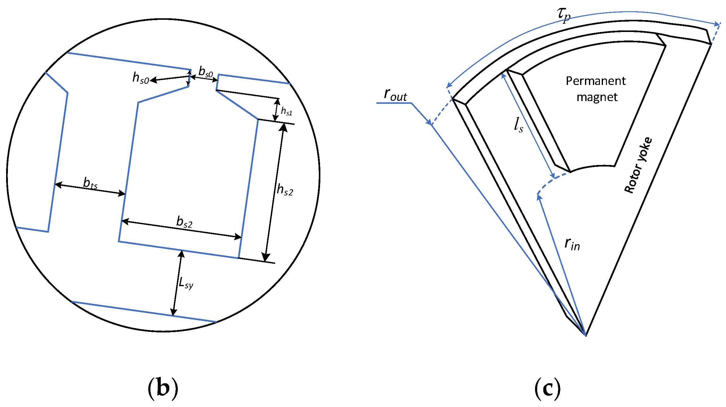
The geometry of the stator slot is illustrated in
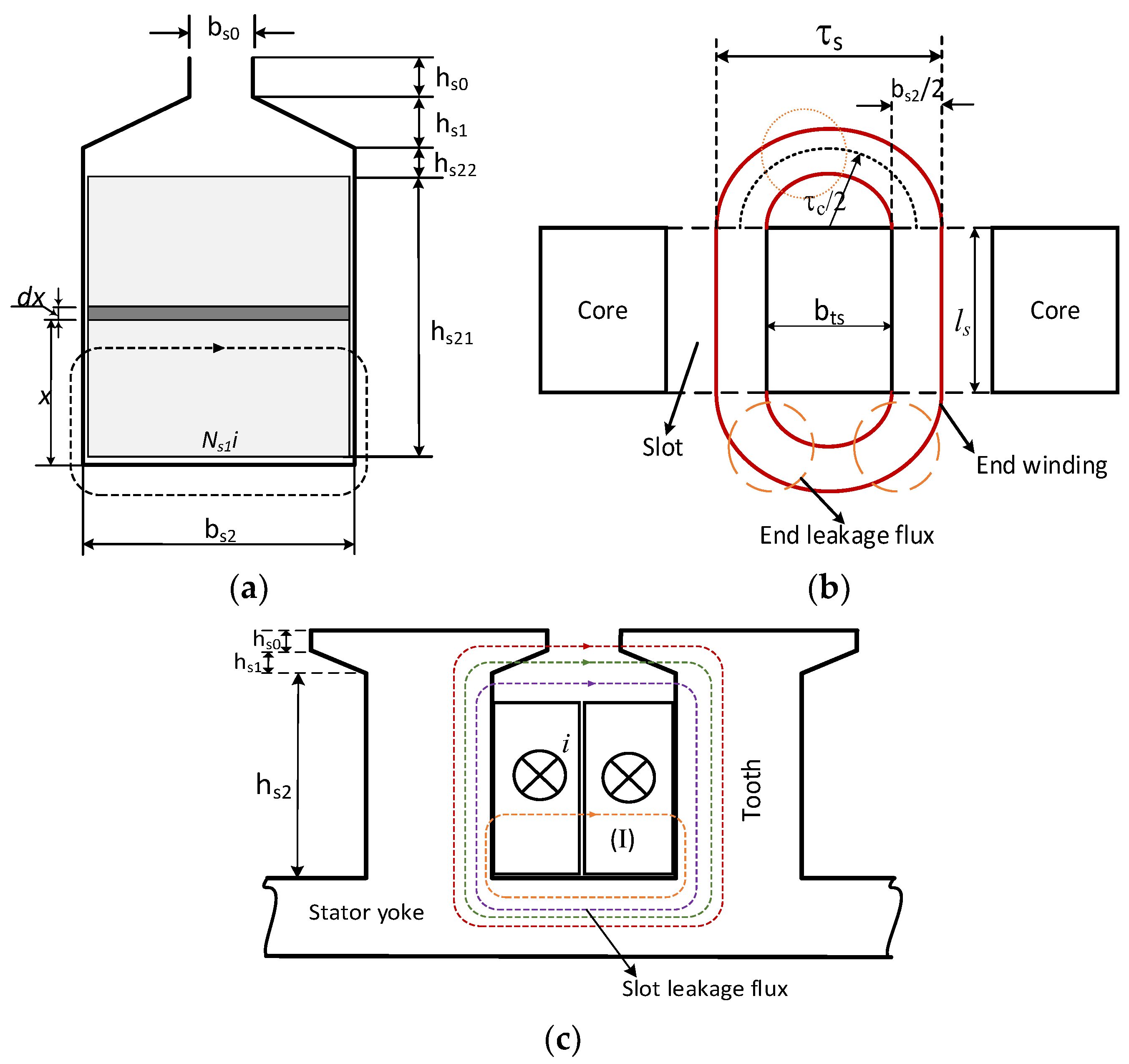
Figure 2b. The slot area, which must accommodate two layers of windings, is calculated using (12), with
kfill being the filling factor, typically ranging from 0.2 to 0.6 depending on the stator winding manufacturing technology [
8]. The conductor diameter
dCu is determined based on the allowable current density and the current flowing through the conductor. The calculated results are summarized in
Table 4.
where
ap is the number of parallel conductors,
Ns1 is the number of conductors per slot.
3.2.3. Determination of Winding Layout
The fraction of the number of slot per pole and per phase
q must be expressed in its simplest fractional form, as follows:
where
a and
b are integer numbers. Given
Qs = 27 and 2
p = 24, the resulting value of q is 3/8.
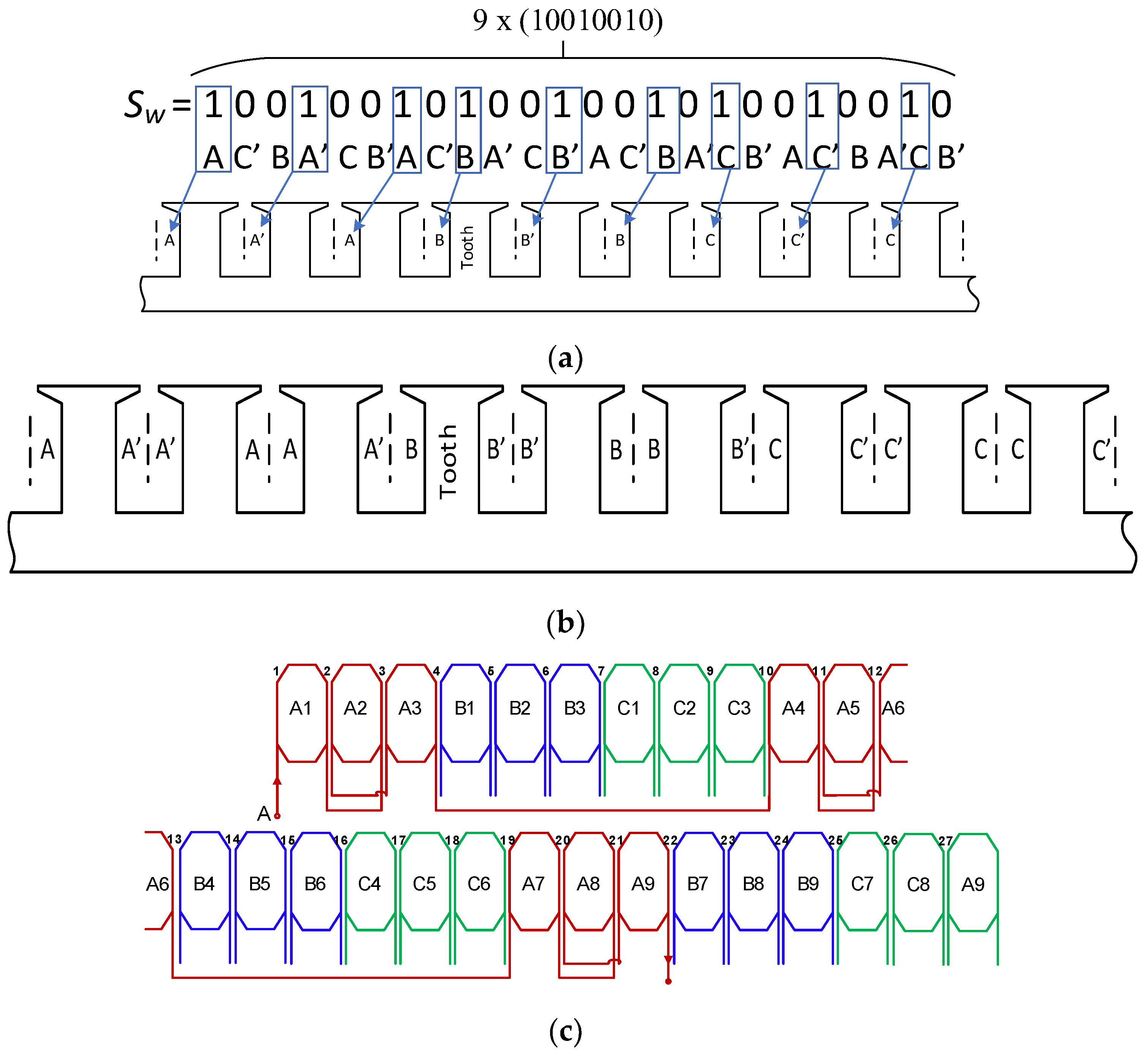
The steps for determining the winding layout are illustrated in the diagram shown in
Figure 8, [
8,
13].
Figure 9a,b illustrate the detailed steps of the winding layout process, while
Figure 9c presents the specific winding connection configuration.
3.3. Formulas for Calculating Stator Slot Dimension
Tooth width is calculated as (14) through outer diameter
Do, slot number
Qs, tooth flux density
Bst, air gap flux density
B1g,max as follows:
where
kFe is the lamination stack factor.
From there, the width of the stator slot can be determined as follows:
The stator yoke thickness (
Lsy) may be calculated from the air gap flux density, stator yoke flux density, and machine diameter as follows:
3.4. Dimension of Rotor and Magnet
Assuming the rotor yoke is not saturated, the rotor yoke thickness can be computed similarly to the stator yoke thickness.
The axial length of permanent magnet (
hpm) is then calculated with Equation (18) [
9] as follows:
where
µrm is relative permeability of magnet,
kC is carter factor.
The permanent magnet configuration is depicted in
Figure 2c. The magnet width
wm is determined by the following:
where
km is the ratio of magnet width to pole pitch.
4. Calculate Electric and Electromagnetic Characteristics
4.1. Inductances of Stator Windings
In rotating electrical machines, the total magnetic flux consists of two components: the main flux (air gap flux) and the leakage flux. The main flux enables the electromechanical energy conversion, while the leakage flux does not participate in the energy conversion process. These two flux components correspond to the magnetizing inductance
Lm and the leakage inductance
Ll. In which the leakage inductance includes components such as the slot leakage inductance
Lslot and the end leakage inductance
Lend and harmonic leakage inductance
Lh [
9,
10]. In the preliminary calculation, the harmonic leakage inductance can be neglected.
The magnetizing inductance
Lm of the machine is computed according to (20). With parameters such as stator active length
ls, the number of turns per phase, and winding factor as follows [
2]:
g’eff is then defined as follows:
Figure 10c depicts the slot leakage flux, which is used to compute the per-phase slot leakage inductance in double-layer windings [
14,
15].
where the specific slot relative permeance
λs is calculated as follows:
For the end-winding leakage inductance, the leakage flux illustrated in
Figure 10b and further explained in
Appendix A can be approximated for double-layer windings as follows [
16].
Therefore, the leakage inductance may be written as follows:
4.2. Power Loss and Efficiency
To evaluate the generator efficiency, it is necessary to calculate the losses occurring during machine operation. These losses include ferromagnetic losses, winding losses, mechanical losses at the bearings, and auxiliary losses.
4.2.1. Calculating Power Loss
The winding losses are determined by phase current and winding resistance, computed as follows:
In Equation (26), this resistance value changes according to temperature as follows:
where the coefficient
kCu characterizes the temperature dependence of copper resistance.
The core loss is mainly in the stator magnetic circuit, calculated as Equation (28) and Equation (29). It depends on the frequency, the flux density of each component, and the mass of the steel [
6].
where
Kt is an experimental loss coefficient;
p10 is the loss value of the steel grade at 50 Hz and at the flux density of 1.0 T;
msy and mst are the masses of the yoke and the teeth.
The mechanical losses can be categorized into friction-related losses and bearing losses. In axial-flux machines, friction losses can be estimated through rotating disk friction factor correlations [
2,
6]. The friction losses are calculated as follows:
where
kf is the friction factor,
ρair denotes the air density,
rsh is the shaft diameter.
The bearing losses may be calculated by using the calculation tools provided by the bearing manufacturer or the following analytical equation [
2]:
where
kbr = 1 to 3 [
2],
mr is the rotor mass,
ns is the speed of rotor.
4.2.2. Electromotive Force
The fundamental internal voltage per phase is determined as follows [
17]:
where
f is frequency of fundamental electromotive force,
N1 is the number of turns per phase winding turns per parallel branch.
4.2.3. Formulas for Calcualting Electromagnetic Power and Torque
The electromagnetic power
Pe, which transfers power across the air gap of the AFPMSG to the stator, is calculated as follows [
8]:
where
θ is the electrical angle between the electromotive force of a phase
E1 and the phase current
Ia.
The electromagnetic torque of machine is calculated as Equation (34) through the following:
where
Îa is the amplitude of the fundamental component of the phase current,
.
4.2.4. The Mass of the Machine Components
With a cylindrical disk-shaped structure, the mass of the stator, and rotor yoke can be easily determined as follows:
where
ρS is density of steel, n is number of generator modules, slot depth
y = hs2 + hs1 + hs0.
The mass of the winding and the mass of the magnets are calculated as follows:
where
ρCu and
ρpm are the densities of copper and magnets,
lCu is the length of the phase winding, and
Vpm is the volume of the magnet.
From
Figure 10b, we can approximate the phase winding length
lCu as follows:
where
bts is tooth width,
ls is stator active length.
4.2.5. Efficiency Calculation
The efficiency of the generator is defined as the output power divided by input power, with the results presented in
Table 4.
where
P1 is the mechanical power applied to the rotor. During operation, losses occur in the stator windings and the stator magnetic circuit. The electromagnetic power
Pe is transmitted across the air gap, resulting in an electrical output power
P2.
4.3. Application of the Analytical Model for AFPMSG Design
After presenting all the calculation formulas as above, we will specifically apply them to the calculation and design of the parameters of the AFPM machine.
Table 4 details the design parameters, including electromagnetic parameters, losses, and the machine’s efficiency. The filling factor
kfill and the ratio of diameter
kd are also presented.
5. FEM Modeling
In this section, an equivalent 2D-FEM model including rotor linear motion and saturation, replacing for a time-consuming 3D-FEM model, for the design of AFFPMSG is proposed. An FEM model comprises the geometry model, meshing, and the physics model with appropriate boundary conditions. The geometry model is directly created using the FEM software environment. The physics model defines each domain using mathematical equations, typically expressed as extended forms of Maxwell’s equations [
18].
5.1. Modeling Principle
The FEM model principle for AFPM is described in
Figure 11. The modeling process begins with defining the coordinates, from which the dimensions are derived. Each component of the electrical machine is defined by different materials. Next, boundary conditions are applied, current density is assigned to the windings, and the magnet magnetization direction is defined. The use of periodic boundary conditions allows for a reduction in model size by simulating a single periodic section rather than the full machine.
In this model, the axial-flux PM machine is simplified to 2D through an axial cross-sectional view taken at a given radius. The computational model consists of the ambient air, half of the stator, the air gap, magnets, and a portion of the upper rotor. To reduce computational complexity, symmetry boundary conditions are applied in this model, enabling representation of only one-third of the machine in the FEM analysis [
18]. The geometry model is illustrated in
Figure 12.
5.1.1. Finite Element Mesh
The accuracy of the results in the finite element problem mainly depends on the precise discretization (meshing) of the considered regions. This process is carried out by discretizing the outer lines of the geometry [
8]. When there is relative motion between the stator and rotor, the initial mesh generation must be sufficiently accurate, especially in areas such as the sliding surface of the air gap, on which the post-processing calculations mainly depend.
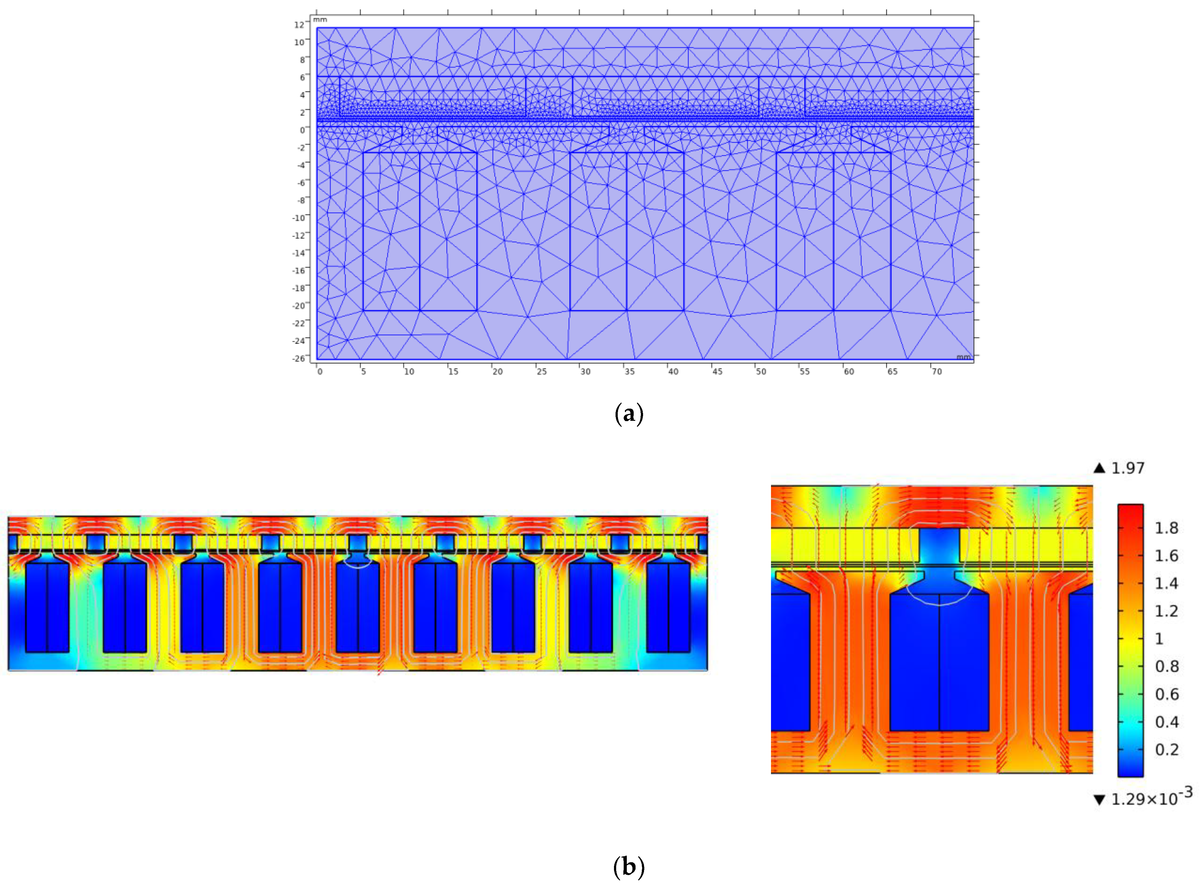
Figure 13a shows the meshing results after refining certain regions of the machine.
5.1.2. Modeling Rotation
The Arbitrary Lagrangian Eulerian (ALE) approach is adopted to simulate rotor motion, preserving mesh integrity in moving regions without deformation [
8,
19]. To accurately simulate rotor rotation in the FEM model, the geometry is partitioned into two distinct regions: a rotating domain representing the rotor and a stationary domain corresponding to the stator. These two domains are connected through symmetry identity pairs. The air gap region is modeled using a sliding interface that divides it into two separate layers. One layer is attached to the rotating rotor domain, while the other remains associated with the stationary stator domain. During the FEM simulation, the rotating domain moves relative to the stationary domain at a specified rotor speed, enabling the dynamic interaction between the rotor and stator to be accurately represented [
8], and the results are presented in
Figure 14.
5.2. FEM Simulation Results
5.2.1. Flux Density Distribution on Airgap and Magnetic Core
Figure 12 presents a partial simulation of the generator, featuring 9 slots and 8 poles. The magnetic flux direction is indicated by arrows in
Figure 13b, with contour lines depicting its trajectory. The magnetic flux predominantly travels between adjacent poles, forming closed-loop paths. The air gap flux density distribution is illustrated in
Figure 15, with both tangential and axial directions considered.
5.2.2. Cogging Torque
In the 2D simulation of an Axial-Flux PM machine, when the rotor and stator are flattened, this part becomes equivalent to a linear machine. The force generated in the linear machine corresponds to the tangential force in the rotating machine [
19]. When the linear force is known, the torque can be approximated by taking the product of the linear force
F and the average radius
r of the machine [
20].
The torque calculation is performed via FEA, employing the Maxwell stress tensor approach [
18,
21], where the surface integral is taken at the middle of the air gap. This approach enables torque calculation through a line integral along path
l. The torque at radius
r is calculated according to the following Equation (42):
The cogging torque is evaluated using the finite element method by computing the torque at various rotor positions under no-load conditions. The corresponding results will be shown in
Section 5.2.5.
5.2.3. Influence of Slot Opening on Distribution of Magnetic Field in Air Gap
Slotting impacts the air gap magnetic field in two primary aspects: it decreases the average magnetic flux per pole and alters the spatial distribution of flux within the air gap, as illustrated in
Figure 16. Slot openings lead to nonhomogeneous flux density in the air gap. The axial flux density is lower at locations facing the slots, which exhibit low magnetic permeability, compared to positions opposite the teeth, where the permeability is higher. The irregular distribution of flux density within the air gap leads to the generation of cogging torque [
10,
20].
Figure 16 shows calculation results of the axial flux density in the middle of the air gap for a closed slot, a semi-open slot, and a fully open slot. Clearly, the slotting effect on the flux density increases with increasing slot opening. The slotting effect is greatest when the slot is fully open. The average flux density in the air gap decreases by about 20% compared to the closed-slot case, and the flux density waveform is significantly distorted. With closed slots, the air gap flux density is homogeneous along the circumferential magnets.
5.2.4. Influence of Slot Opening on Internal Voltage
In
Section 5.2.3, the influence of the slotting effect on the magnetic field in air gap was discussed. This section presents the influence of the slotting effect on the internal voltage. The back electromotive force
e can be calculated as follows [
8]:
where
and
represent integration domains corresponding to cross-sectional areas,
S is the cross-sectional area of the equivalent conductors on both the go and return paths of the stator windings, and
A is the magnetic vector potential.
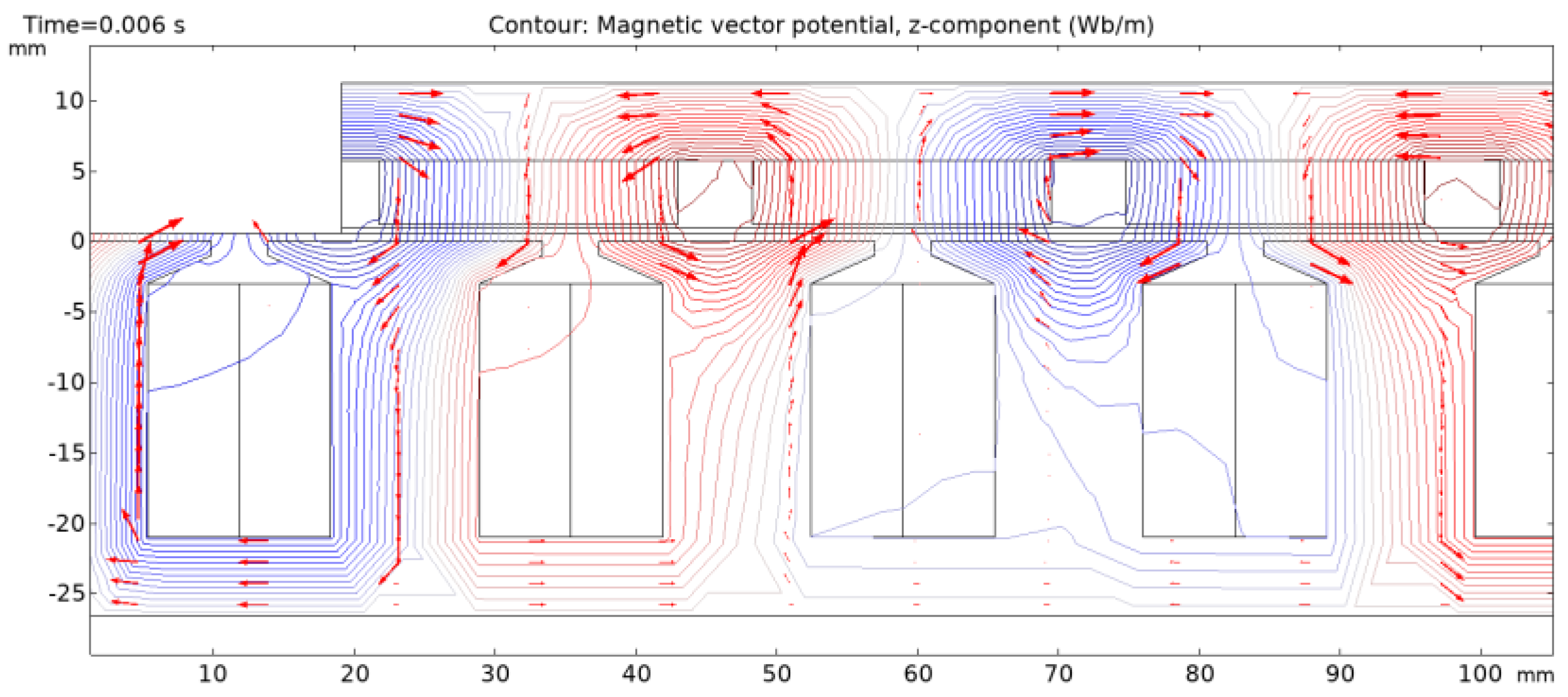
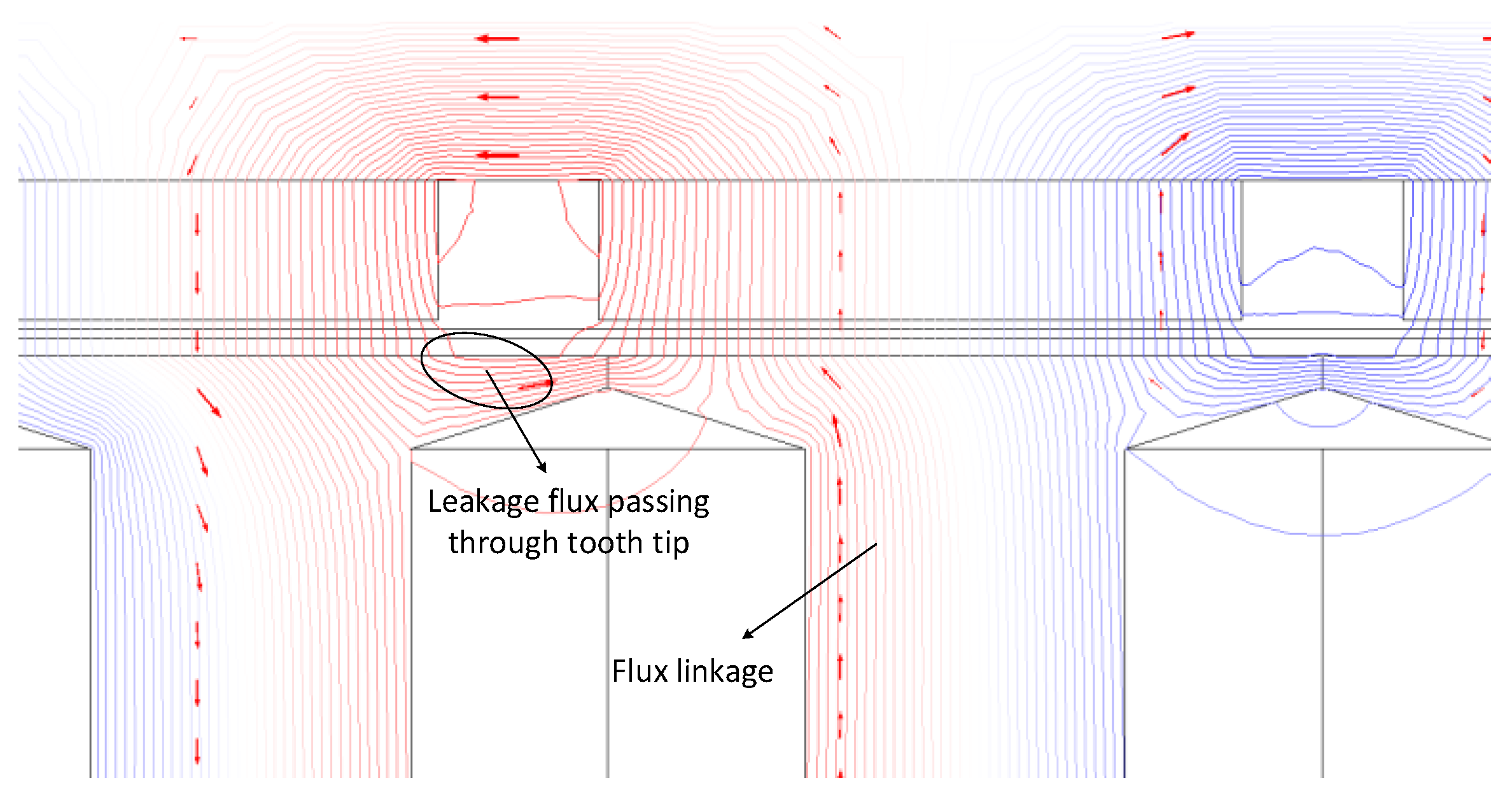
Figure 17 illustrates the simulated flux line distribution for an AFPM machine with nearly closed-slot. It can be observed that the leakage flux traversing the tooth tips causes distortion in the machine’s internal voltage waveform.
Figure 18 presents a comparison of the internal voltage waveforms for AFPM machines with closed, semi-open, and fully open stator slots. The results indicate that the slot opening has a significant influence on the internal voltage amplitude. A larger slot opening leads to reduced flux linkage through the stator tooth, thereby decreasing the internal voltage amplitude. As a result, a greater number of winding turns is required to achieve the rated voltage. Conversely, when the slot-opening width is small, increased leakage flux through the tooth tips further reduces the flux linkage and electromotive force amplitude.
5.2.5. Effect of Design Parameters on Torque
Figure 19 illustrates the cogging torque as a function of time and slot opening. In general, predicting the variation in cogging torque with respect to slot opening is challenging due to the effect of magnet width and slot opening, the combination of slot and pole, and magnetic saturation [
22]. As shown in
Figure 19, the simulation case with a 0.5 mm slot opening exhibits the minimum peak-to-peak cogging torque, while zero cogging torque is observed for the closed-slot configuration. This occurs because the air-gap reluctance becomes constant when the slot opening width approaches zero. Moreover, cogging torque is proportional to the derivative of the air-gap reluctance with respect to the rotor position. Nevertheless, in practical designs, the slot opening must be sufficiently wide to accommodate the winding.
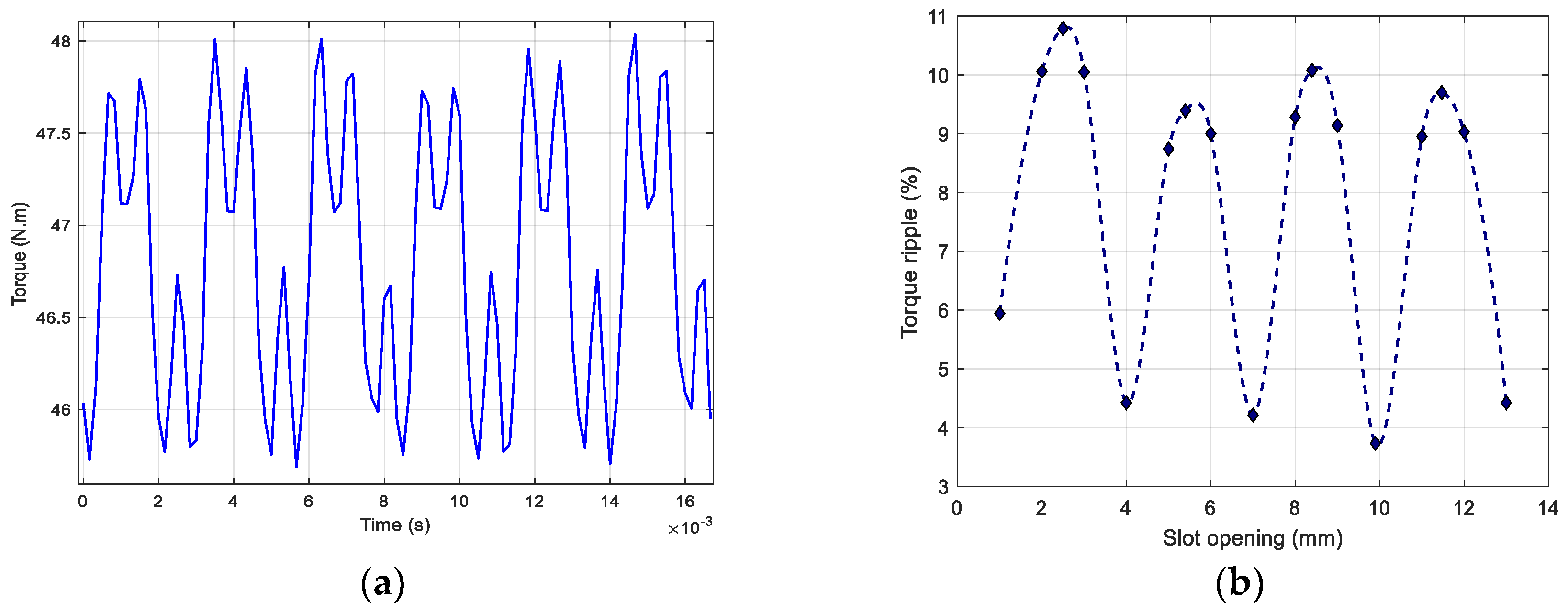
Torque ripple (%) is defined as the ratio between the difference in maximum and minimum torque to the average torque.
Figure 20 illustrates the variation in torque ripple percentage with different slot opening values, with the magnet width to pole pitch ratio being 0.75. The results show that torque ripple varies significantly with slot opening, exhibiting a wide range of fluctuation. Notably, when the slot opening reaches 10 mm, the torque ripple attains its lowest value; however, the average torque also experiences a considerable reduction. At a slot opening of 4 mm, although the torque ripple is slightly higher, the average torque is significantly improved. This raises the issue of optimizing between reducing torque ripple and ensuring high output torque performance.
6. Conclusions
This paper has proposed an effective method in terms of the compromise between computational accuracy and time for the design of axial-flux permanent magnet synchronous generators in VAWT applications. An analytical model with derived analytical equations has been developed and explained. The effectively equivalent auto-transient 2D-FEM model, including magnetic saturation and rotor linear motion for the calculation of electromagnetic performances of the AFPMSG, has been proposed instead of using a time-consuming transient 3D-FEM model. This is an essential tool in the design process of the AFPMSG. The tool is helpful for the optimization of the electrical machines for minimizing cogging torque. A 1.35 kW AFPMSG has been designed, satisfying the given requirements of power, voltage, power factor, efficiency, and cogging torque. Additionally, the obtained results show the impact of slot opening on AFPMSG’s performances, including flux density, induced voltage, and cogging torque.
