1. Introduction
Wind energy is one of the most promising areas in the field of renewable energy, offering an environmentally friendly and sustainable way of generating electricity. The efficiency and reliability of wind turbines largely depend on their ability to adapt to dynamic environmental conditions, including changes in wind speed and direction. In this context, the development and implementation of adaptive control systems are key to optimizing the performance and extending the service life of wind turbines. Among modern approaches to adaptive wind turbine control, several key directions can be distinguished: pitch control [
1], which increases energy conversion efficiency but requires complex mechanisms and regular maintenance; variable speed control [
2], which maintains an optimal power coefficient and reduces dynamic loads, though it complicates control systems and increases demands on drive components; and the use of intelligent control systems, such as neural networks and adaptive fuzzy controllers [
3], which provide high adaptability but require significant computational resources and complex configuration. A promising direction is automatic rotor height regulation [
4], which involves adjusting the rotor height of the wind turbine based on wind parameters. This allows for energy capture optimization and reduced turbulence effects. Advantages include the ability to operate across a broader range of wind conditions and reduced mechanical stress on the structure. However, implementing such systems requires complex mechanical solutions and may increase the mass and cost of the installation. Each of these methods has its own advantages and limitations. Pitch and variable speed control allow effective adaptation to changing wind conditions but require complex and costly control systems and mechanical components [
1]. Intelligent control systems offer a high level of adaptability, but their implementation is associated with additional costs for computational resources and tuning [
5]. Automatic rotor height regulation represents a promising approach for optimal rotor positioning under various conditions, but further research is required to overcome technical and economic challenges [
6].
The aim of this study is to develop an automatic rotor height regulation system for a Vertical-Axis Wind Turbine (VAWT) using a screw drive, based on the principles of adaptive control. The work will include an analysis of existing technologies, the development of a mathematical model of the system, and an assessment of its performance under various operating conditions. The proposed approach is expected to improve energy conversion efficiency and reduce dynamic loads on the structure, thereby increasing the reliability and longevity of wind turbines. In this project, the rotor height adjustment mechanism is implemented through a ball screw drive model HIWIN R32-10A, chosen for its high load capacity, precision, and efficiency in vertical positioning systems, which ensures stable operation under varying aerodynamic loads. The control system is built on a microcontroller ARM Cortex-M0+ (RP2040) from the Raspberry Pi Foundation, programmed using C/C++ SDK or MicroPython (via Thonny IDE or Visual Studio Code), providing sufficient computational resources for adaptive algorithms while maintaining energy efficiency.
2. Materials and Methods
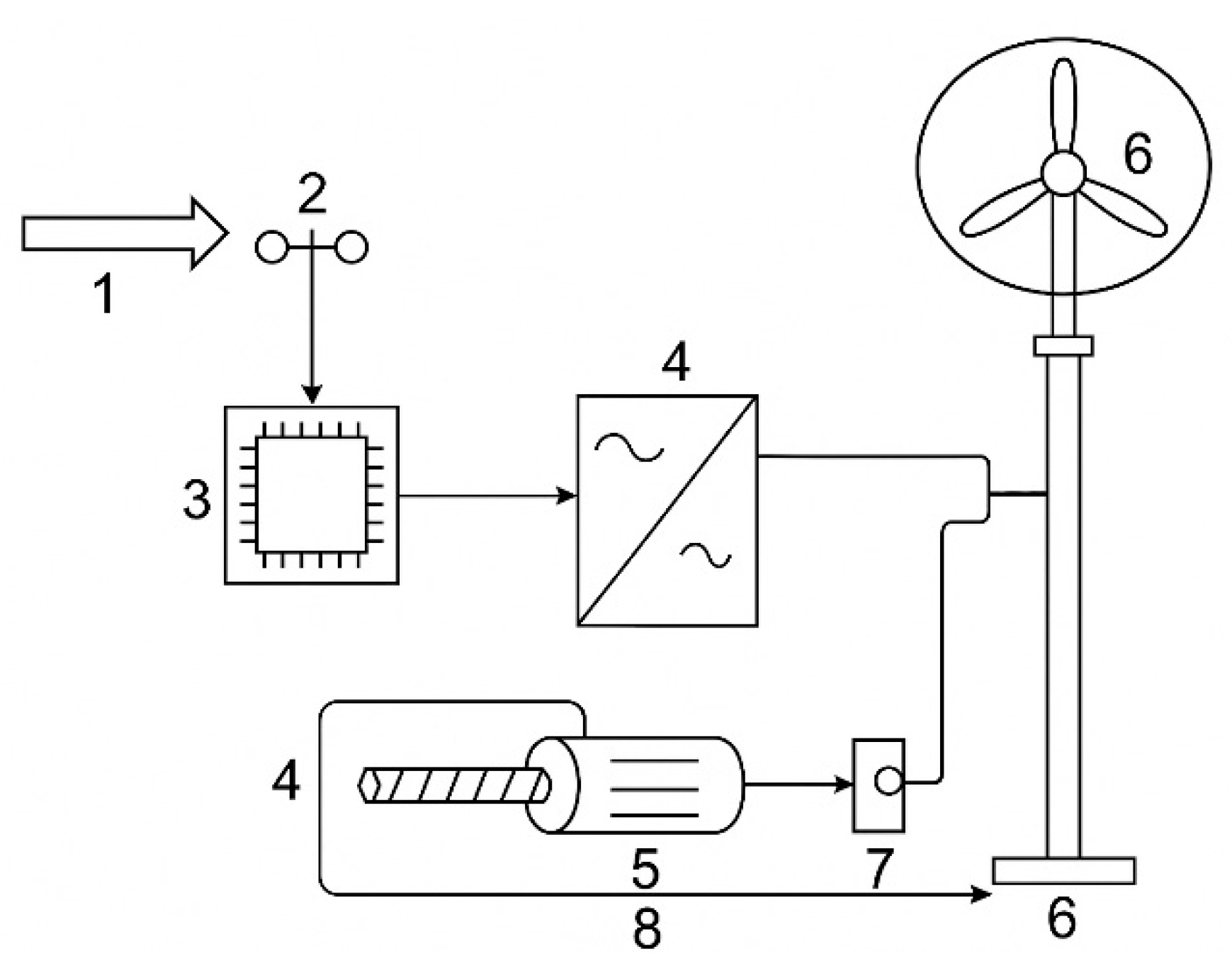
Figure 1 shows the automatic rotor height regulation system of an off-grid wind turbine 600 W with Darrieus & Savonius, manufactured by TYPMAR, Shenzhen, China model CXF-600W using a ball screw drive produced by HIWIN in Offenburg, Germany, model R32-10A. The operating principle is based on adaptive height control depending on wind speed. The airflow (1) impacts the anemometer (2), which measures wind speed and direction and transmits the data to the microcontroller ARM Cortex-M0+ (RP2040) from the Raspberry Pi Foundation (3) [
7]. The embedded software programmed Python 3.11 analyzes the received data and makes decisions regarding rotor height adjustment. A frequency converter (4) is used to control the height by regulating the voltage supplied to the screw drive electric motor (5). The electric motor activates the screw mechanism, smoothly changing the position of the rotor (6) to enhance operational efficiency or provide overload protection.
The system is equipped with a feedback mechanism that includes a position potentiometer (7), which records the current rotor position and sends a signal through the feedback loop (8) to the microcontroller (3). This enables precise movement control and minimizes excessive adjustments. The automation of the height control process reduces the need for manual intervention, extends equipment service life, and enhances the reliability of wind turbine operation under changing weather conditions.
During the operation of a wind turbine, its rotor is subjected to various external loads, including aerodynamic forces from the wind flow, gravitational forces, and forces arising within the drive mechanism. Optimizing the system’s performance requires an accurate mathematical description of the rotor’s motion, which enables the prediction of its behavior under different operating conditions and the development of effective control algorithms [
8].
One of the key equations describing the rotor’s vertical motion is a differential equation based on Newton’s second law. This law states that the net force acting on an object is equal to the product of its mass and acceleration [
9]:
where
x(
t)—vertical position of the rotor;
m—mass of the rotor (20 kg);
g—acceleration due to gravity (9.81 m/s
2);
Fapplied—force generated by the screw drive;
Ffriction—friction force.
The force
Fapplied can be expressed through the motor torque. Based on the condition of motion transmission through the screw drive [
10]:
where
M—motor torque;
d2—mean diameter of the screw;
ηscrew—efficiency of the screw drive.
Substituting this into the equation of motion gives the following [
8]:
Next, the friction force in the thread was expressed, which includes two components: dry friction, dependent on the normal force
N, and viscous friction, proportional to velocity. The normal force is determined through the load force, allowing both types of resistance to be comprehensively accounted for in the mechanical model:
Thread friction is calculated using the formula [
11]
where
f—coefficient of dry friction;
N—normal force;
b—coefficient of viscous friction,
dx/
dt—velocity of the rotor.
By substituting into the main equation of motion, the following was obtained:
The second-order differential equation given by Formula (6) describes the rotor’s motion. Since the movement is defined by the motor’s rotation angle
θ(
t), it is possible to proceed with calculations using angular variables. The relationship between linear displacement and angular rotation is given as follows [
12]:
Next, differentiation was performed twice:
The obtained values were then substituted into Equation (6):
For the effective control of the wind turbine’s screw drive, it is essential to consider the dynamics of the electric motor, which serves as the primary component for converting electrical energy into mechanical motion. The electric motor controls the screw drive by adjusting its speed and generating the torque required to raise or lower the rotor. To accurately describe the processes occurring within the motor, a mathematical equation based on electrical circuit laws is used. When the motor is powered by direct or alternating current, its winding follows the fundamental voltage balance equation, which accounts for the winding resistance, inductance, and back electromotive force (EMF). This equation determines the relationship between the current in the winding, the applied voltage, and the rotor’s rotational speed. The fundamental equation of the motor armature electrical circuit is given by [
11]
The electric motor is the key component in controlling the screw drive, converting electrical energy into mechanical work. It is important to consider its characteristics to determine how changes in input parameters (voltage, current) affect the generated torque, angular velocity, and, consequently, the overall movement of the system. The screw drive controls the displacement of the wind turbine rotor, and its behavior is governed by several interrelated equations: the torque equation, the angular velocity equation, and the voltage balance equation in the motor circuit. Incorporating these equations into the dynamic model of the system allows for the analysis of the mechanism’s operation and the development of effective control algorithms. The torque generated by the motor is defined by the following relationship [
12]:
This equation shows that the torque is linearly dependent on the current flowing through the motor winding. By controlling the current, it is possible to regulate the rotational dynamics of the motor. The relationship for angular velocity is given by [
13]
This is a fundamental relationship that links the rotational speed to the shaft’s angle of rotation. Using this expression allows for consideration of the system’s kinematic characteristics. By applying Kirchhoff’s law to the motor winding’s electrical circuit, the following can be written [
14]:
This equation shows how the voltage across the motor winding varies depending on resistance, inductance, and back EMF. It allows for accounting for the influence of all electrical parameters on the motor’s operation. After transforming Equation (12), the motor equation was obtained:
This differential equation describes the dynamic behavior of the motor under varying input voltage. In accordance with Equation (8), the screw drive motion equation takes the following form:
The presented equations form the foundation for analyzing the electromechanical system of the screw drive. They illustrate how voltage, current, torque, and angular velocity interact within the system, influencing the rotor’s displacement. Further analysis and modeling of these equations enable the optimization of system control, ensuring the precise and efficient regulation of the wind turbine rotor’s height.
3. Results and Discussion
To analyze the dynamic characteristics of the screw drive and the rotor height control system of the wind turbine, it is convenient to transform the differential equations into the operational form using the Laplace transform. This approach allows the system to be represented by transfer functions, which significantly simplifies the analysis of its behavior in the frequency domain and facilitates the development of control algorithms and the assessment of system stability. The Laplace transform is applied to the rotor motion and electric motor equations, resulting in a system of algebraic equations that describe the relationship between the system’s input and output parameters. Let us consider the main steps of converting to transfer functions. By applying the Laplace transform to the system dynamics equation, the following was obtained:
This equation shows how the motor torque affects the angular displacement of the rotor, taking into account mass, damping, and external forces. Solving Equation (15) with respect to
θ(
s), the following was obtained:
Next, the transfer function of the mechanical part of the system was derived:
This transfer function describes the response of the mechanical system to changes in the motor torque, taking into account the rotor mass and damping forces. By applying the Laplace transform to Equation (13), the following was obtained:
By deriving the transfer function of the motor, the following was obtained:
This transfer function describes the conversion of the input voltage
U(
s) into the torque
M(
s), taking into account the electrical parameters of the motor. The complete dynamic model of the system includes both the motor and mechanical system transfer functions:
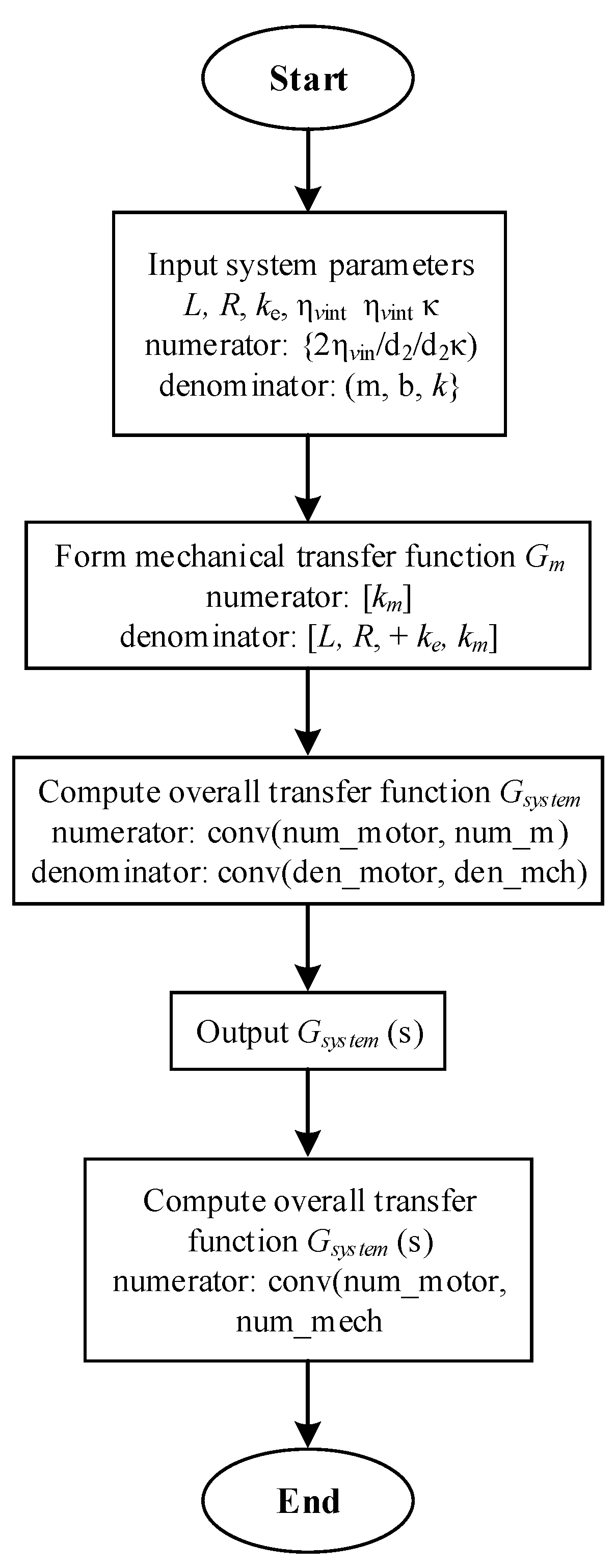
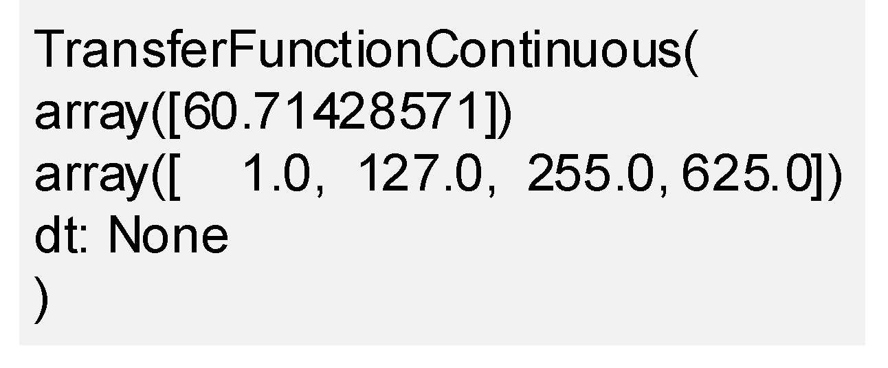
For numerical calculation and the derivation of the transfer function, a program was developed in Python 3.11.0. The block diagram of the program is shown in
Figure 2, and the program output is presented in
Figure 3.
According to
Figure 3, the transfer function of the screw drive control system was obtained:
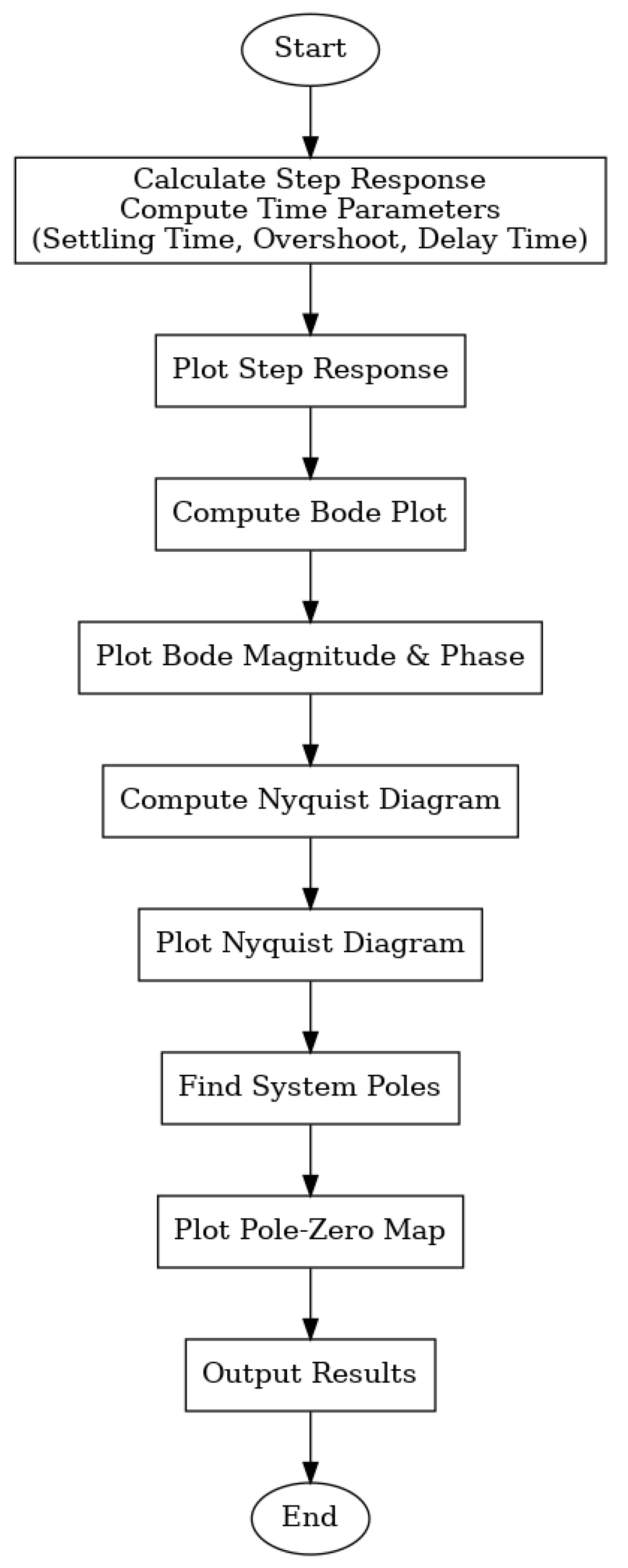
The Laplace transform made it possible to represent the system in terms of transfer functions, which significantly simplifies the analysis of its dynamic characteristics and the development of control algorithms. The obtained expressions allow for the investigation of the influence of various system parameters, such as inertia, damping, and the transfer properties of the motor and screw drive. This approach also opens up the possibility for further analysis of system stability and optimization of its performance. The code presented below performs the simulation of the dynamic control system of the screw drive using transfer functions. The objective is to analyze the system’s frequency and time responses to assess its stability and efficiency. First, the main system parameters are defined, including the damping coefficient b, motor parameters (inductance, resistance, back EMF and torque constants), and the mechanical parameters of the screw drive. Then, the transfer functions of the mechanical part and the motor are calculated, after which they are combined into the overall system transfer function. The final stage involves analyzing the system’s dynamic characteristics. The generated plots help visually interpret the results and determine how effectively the system responds to changes in control input.
The program workflow block diagram is shown in
Figure 4.
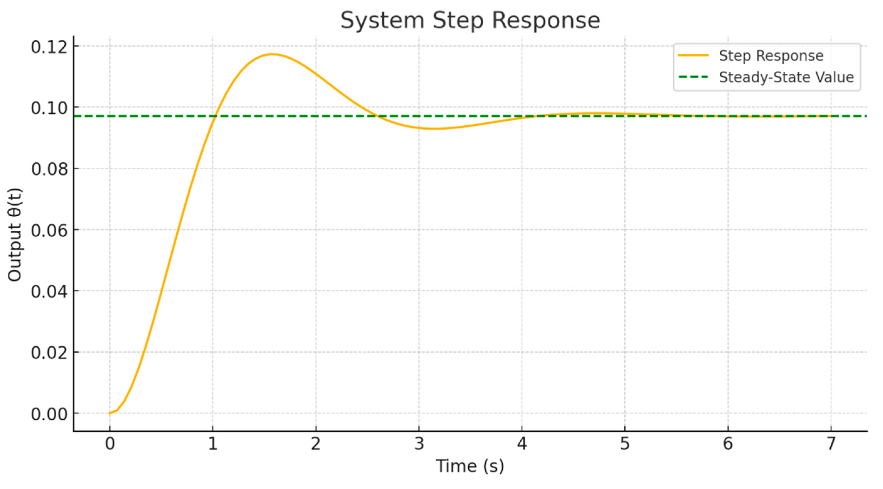
The transient response shown in
Figure 5 reflects the system’s behavior under the influence of a unit step input, allowing for the evaluation of its dynamic performance. This analysis demonstrates how quickly and stably the system responds to a sudden change in the input parameter—a critical factor for drive mechanisms where precise and timely positioning is required.
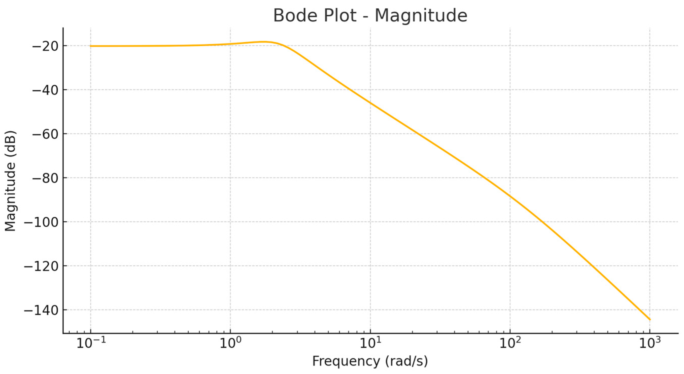
The graph shows that after applying a step input, the system exhibits a smooth rise in the output value with a moderate overshoot of approximately 20.8%. The settling time is less than one second (~4 s), indicating a high-speed response. The absence of prolonged oscillations and the rapid achievement of a steady state indicate a sufficient level of damping and proper tuning of the model parameters. This behavior is characteristic of stable systems with a good balance between response speed and the prevention of undesirable oscillations. The frequency response (Bode plot) shown in
Figure 6 allows for the assessment of how the system reacts to harmonic signals of varying frequencies. This is important for understanding which frequency ranges pass through the system without distortion and which are attenuated. This is particularly critical for drive systems that are susceptible to external vibrations and noise.
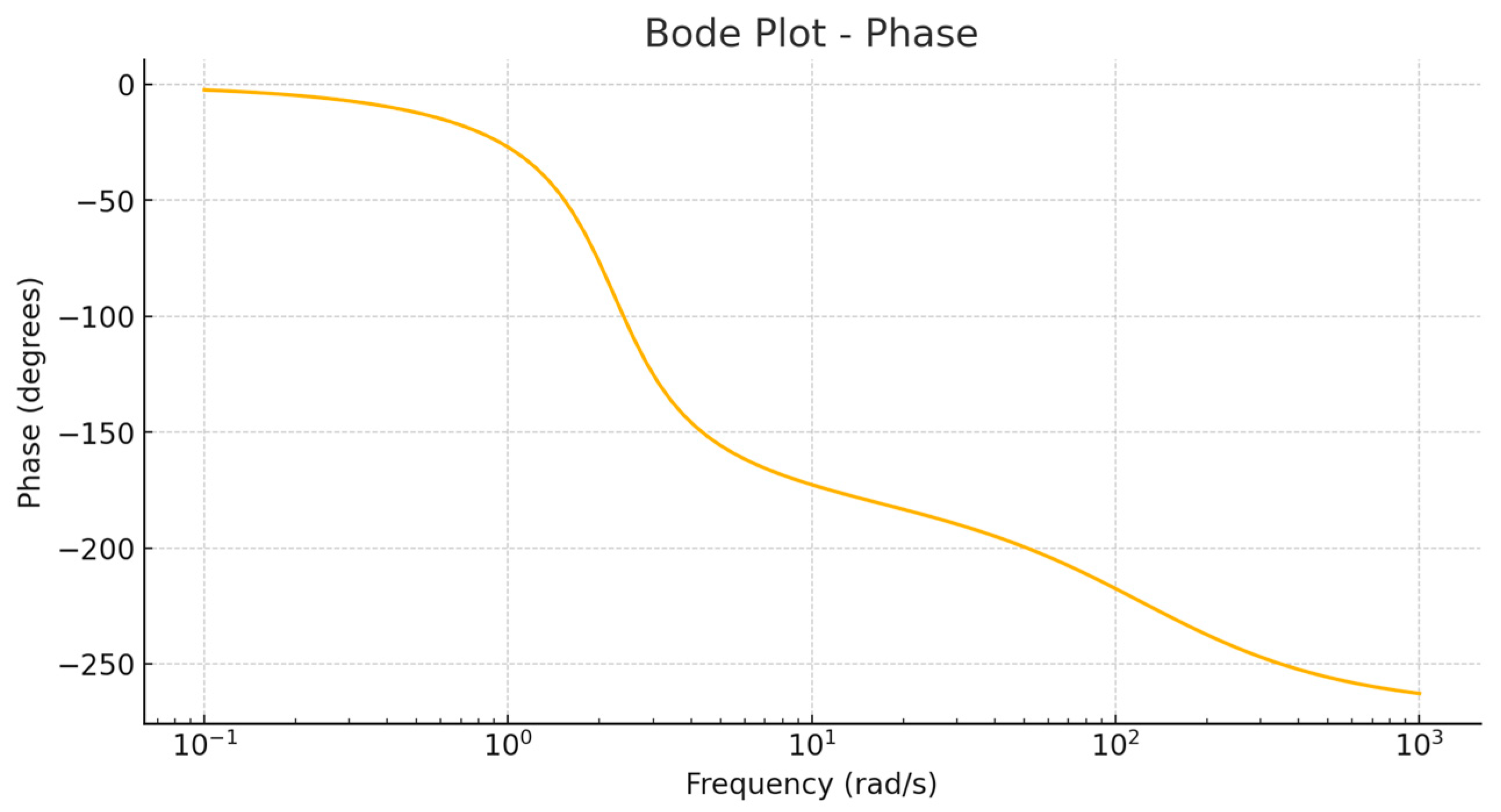
The amplitude–frequency response (AFR) graph displays typical low-pass filter behavior: in the low-frequency range, the gain remains stable, allowing the system to effectively respond to slowly varying signals. As the frequency increases, a gradual decrease in amplitude is observed, indicating the system’s ability to suppress high-frequency oscillations and noise. The absence of sharp drops and peaks suggests that the system is not prone to resonance phenomena, which enhances its operational reliability. The phase–frequency response (PFR) shown in
Figure 7 illustrates the phase shift of the output signal relative to the input as a function of frequency. Analyzing the phase shift allows for the assessment of system behavior under automatic control conditions, where significant phase distortions can lead to reduced stability or even oscillatory modes.
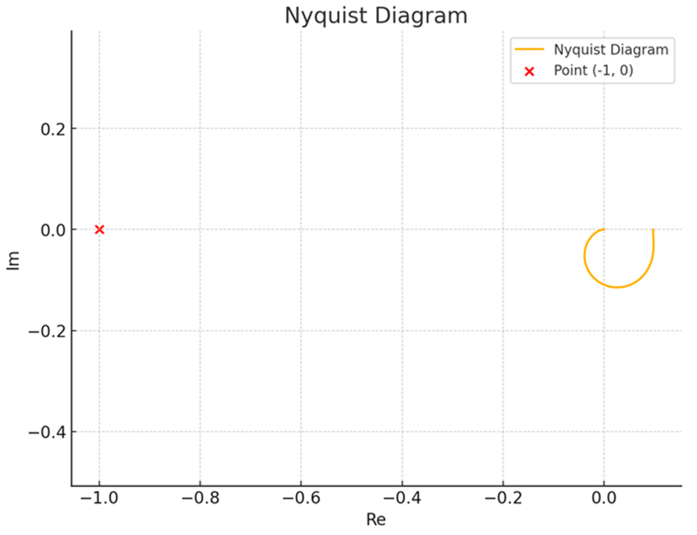
The presented graph shows a smooth decrease in the phase angle as the frequency increases. This behavior is typical for stable systems with a predictable phase shift. The absence of sharp jumps or regions where the phase abruptly crosses critical values (e.g., −180°) indicates the system’s stability under various frequency influences. Such a phase profile ensures that the system can operate within feedback loops without the risk of losing stability. The Nyquist diagram is a classical tool for analyzing control system stability in the frequency domain. It allows for determining the presence and magnitude of the stability margin through a visual assessment of the curve’s position relative to the critical point (−1, 0). In
Figure 8, it can be seen that the curve encircles the origin but does not intersect or enclose the critical point. This indicates a stable system with a sufficient stability margin. This behavior confirms that, with the given parameters, the model is not prone to self-excitation and will operate correctly even under changing external conditions or variations in the input signal parameters.
The location of the system poles on the complex plane is a fundamental criterion for assessing stability. Poles located in the left half-plane ensure a decaying system response without sustained oscillations, whereas the presence of poles in the right half-plane would indicate instability. In
Figure 9, it is evident that all poles are situated in the left half-plane, fully complying with stability criteria. The presence of complex conjugate poles with negative real parts explains the moderate overshoot observed in the transient response. This confirms that the system is tuned for an optimal balance between responsiveness and stability.
The comprehensive analysis of the dynamic and frequency characteristics of the screw drive control system has confirmed its stability and efficiency. All graphs demonstrate balanced system behavior: rapid response to control inputs, the suppression of high-frequency oscillations, the absence of critical phase distortions, and a significant stability margin. These results indicate the accuracy of the developed mathematical model and its suitability for practical application in automatic rotor height control systems for wind turbines.
