Proceeding Paper

Cyber-Physical System for Treatment of River and Lake Water †

by
Diana Syulekchieva
1,
Blagovesta Midyurova
1,*,
Aleksandar Mandadzhiev
1,
Ivaylo Belovski
1,
Todor Mihalev
2 and
Elena Koleva
3
1
Department of Electronics, Electrical Engineering and Mechanical Engineering, Burgas State University “Prof. Dr. Assen Zlatarov”, 8000 Burgas, Bulgaria
2
Executive Environment Agency, 8001 St. “Perushtitsa”, 67, p. k. 675, 8001 Burgas, Bulgaria
3
Department of Production Automation, University of Chemical Technology and Metallurgy, 1000 Sofia, Bulgaria
*
Author to whom correspondence should be addressed.
Presented at the International Conference on Electronics, Engineering Physics and Earth Science (EEPES 2025), Alexandroupolis, Greece, 18–20 June 2025.
Eng. Proc. 2025, 104(1), 65; https://doi.org/10.3390/engproc2025104065 (registering DOI)
Published: 29 August 2025

Abstract

Water plays a fundamental role in sustaining biological processes, ecological functions, and economic systems. However, the progressive pollution of water sources compromises these functions, posing significant threats to water purity, human well-being, and environmental sustainability. Human activities, such as industrial waste, agriculture, and urbanization, alongside natural processes, are major contributors to the deterioration of surface water quality, which in turn leads to environmental and economic risks. The decline in water quality results in issues such as waterborne diseases, loss of biodiversity, and a shortage of clean water for consumption and industrial use. This paper emphasizes the critical need for maintaining good water quality and the importance of implementing effective strategies for the removal of physical, chemical, and biological contaminants. In response, this work presents an intelligent embedded system (electronic control unit, ECU) developed as part of a modular filtration system designed to improve surface water quality, provide more precise water analyses, and perform tests within a controlled environment.

1. Introduction

Water is both the most sensitive component of our ecosystem and an indispensable driver of human development and industrial growth. Maintaining good water quality is essential for all stakeholders. Regardless of its intended purpose—whether for drinking, industrial and agricultural uses, recreation, fishing, or the maintenance of aquatic organisms—water quality is determined by its physical, chemical, and biological properties, which are necessary to maintain these functions within acceptable norms [1].
Water pollution has been recognized as a critical global problem by the United Nations, emphasizing that insufficient access to clean water can jeopardize the survival of ecosystems and species. Due to the high solubility of water, harmful substances are easily mixed in it, making it hazardous to both human health and the environment [2].
The primary sources of water pollution include industrial discharges, agricultural runoff, and urban runoff. Industrial activities release harmful pollutants—such as heavy metals and toxic chemicals—directly into water bodies. Agricultural runoff, the leading cause of surface water pollution, carries pesticides, fertilizers, and animal waste into rivers and lakes, leading to nutrient pollution and eutrophication. Furthermore, urban runoff, also known as stormwater, washes away pollutants from paved surfaces such as streets, roofs, and sidewalks, including hydrocarbons from roads, metal compounds, sanitary waste, and untreated sewage before flowing into nearby water systems [3].
In order to produce clean water for different purposes such as drinking, medical, and pharmaceutical applications, the water should go through a filtering process. This process represents removing or reducing the concentration of particular matter, such as bacteria, viruses, parasites, as well as other unwanted chemical and biological contaminants. Safe water supply is of fundamental importance for maintaining human life and preserving ecosystems [4]. Basically, such a system consists of a water pump and a system of different water filters (depending on the number of filtering stages). The pumped water goes through the filters, and the quality of the filtered water is investigated in a laboratory. The investigated water source could be any natural water source, so the water filtering system should be portable and, therefore, powered by a battery. However, such a rudimentary system (battery, water filters, and pump) cannot provide important information, such as the flow rate at which the experiments were conducted, the total quantity of water that has gone through the system, and the change intervals of the filters. Moreover, the system is battery powered, so of crucial importance is the monitoring of the battery voltage. Therefore, the main objective of this work is to develop an intelligent system that is able to perform the following tasks:
  • Monitoring battery voltage;
  • Measuring flow rate;
  • Computing the total quantity of water that has passed through each filter stage;
  • Alerting the user to change each filter if the user-defined water quantity has passed through the corresponding filter;
  • Starting and stopping the water pump;
  • Driving a TFT display to show system information needed by the user.
The system will find application in the following areas: ensuring water filtration and improving river and lake water quality, and conducting analysis and testing in a controlled environment.

2. Cyber-Physical System for In Situ Treatment of Surface Waters: Technical Description and Process Overview

Block Scheme of the Electronic Control Unit of the Water Filtering System

The developed electronic control unit (ECU), in combination with the water filtering system, represents an embedded system. The ongoing efforts to integrate computational elements into larger systems has led to the occurrence of a new class of systems, called embedded systems [5]. This term has been generalized and extended to newer terms such as cyber-physical and IoT (Internet of Things) systems, where more emphasis is placed on physical objects, e.g., cars, airplanes, or smart devices [6]. In recent years, embedded systems have played an important role in IoT architecture, which incorporates wireless sensors, wearable electronic devices, and mobile smart devices [7]. Figure 1 shows the block scheme of the electronic control unit (ECU) of the water filtering system. The heart of the ECU is the microcontroller unit (MCU) PIC16LF18877 from Microchip. This MCU represents an eXtreme Low Power (XLP) microcontroller with RISC architecture and has been chosen because of its low run and sleep currents, enabling battery-powered applications, such as in the water filtering system. The sleep current goes down to 50 nA, while active mode currents are as low as 32 μA/MHz [8]. The flash program memory is 56 KB. The battery voltage is regulated at 5 V and 3.3 V using two linear voltage regulators, LM317t. A voltage level of 3.3 V is needed to power the MCU and the TFT display, and 5 V is needed to supply the water flow sensor.
  • RESET button:
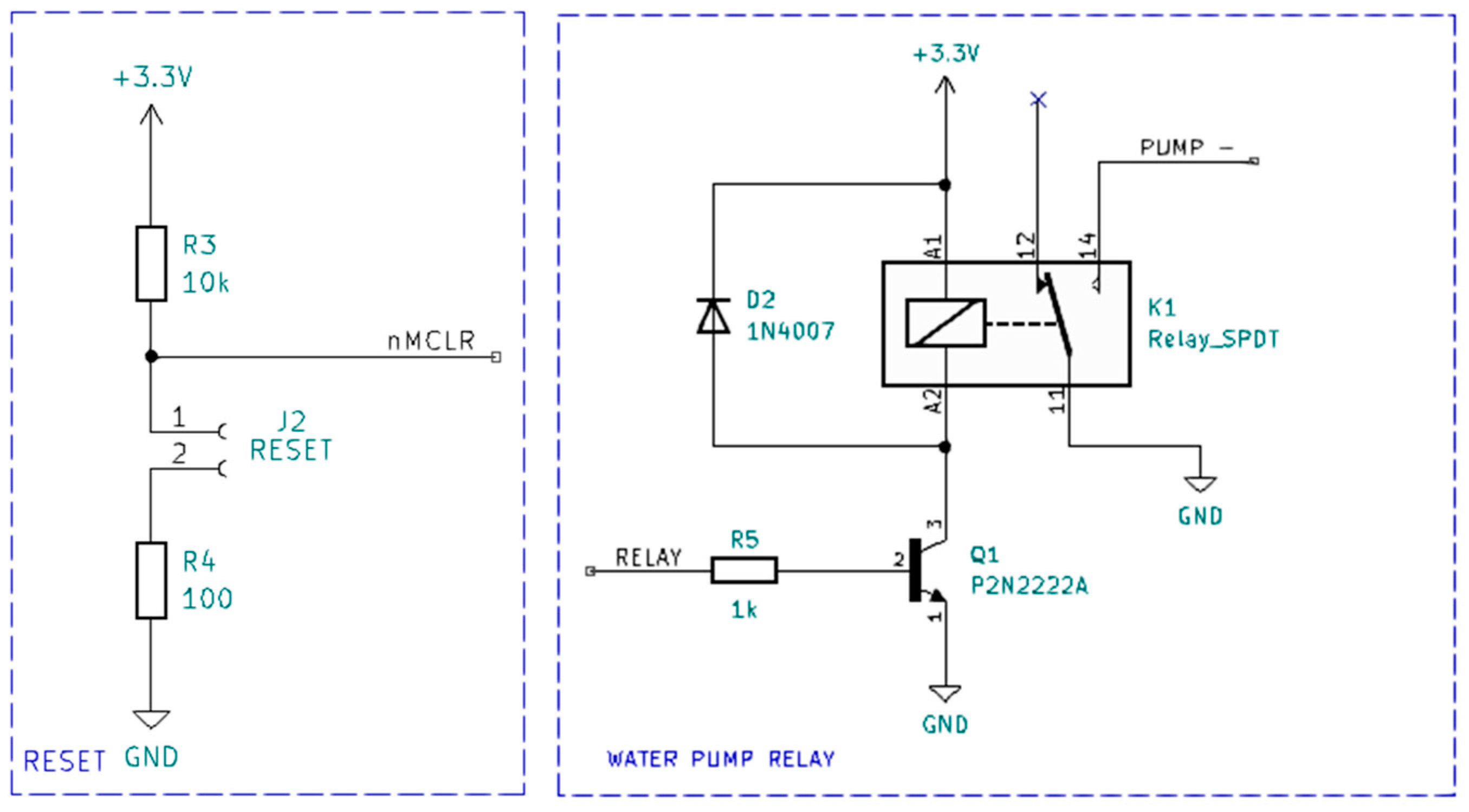
A RESET button is attached on Pin VPP/   MCLR - / RE3, which enables the user to reset the MCU.
  • Battery status:
The battery voltage is sensed using a voltage divider consisting of resistors of 30   k Ω and 7.5   k Ω , the output of which is connected to the RA0 pin of the MCU. This pin is used as the analog input to the 10-bit analog-to-digital convertor (ADC) of the MCU. With a 12 V input to the voltage divider, its output level connected to the ADC will be a maximum of 2.4 V. Using the 10-bit ADC with positive reference Vdd (MCU supply voltage, 3.3 V) and negative voltage reference Vss (Ground), the resolution for the output voltage of the voltage divider is 3.2 mV. The value of the measured battery voltage is computed in software.
  • External oscillator circuit:
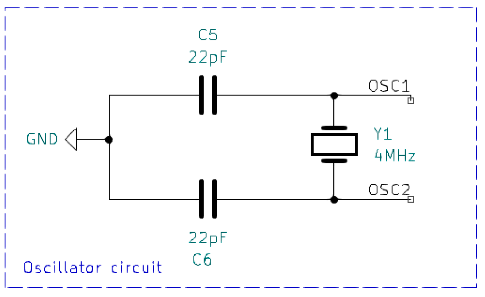
The clock source for the MCU has been chosen to be an external crystal oscillator with a 4   M H z frequency, corresponding to the XT setting of the MCU: Medium Gain Crystal or Ceramic Resonator Oscillator mode (between 100   k H z and 4   M H z ). The PLL (phase-locked loop) is enabled, yielding a clock frequency of 16 M H z . Figure 2 shows the circuit for the external oscillator.
  • Start–stop relay:
In order to start and stop the water pump, a relay is driven by the RC0 GPIO (general purpose input output) pin of the MCU, now configured as output. The relay is Finder F36119-003A, which has a 3 V coil voltage and load contact characteristics of 10 A/30 V DC, which are completely sufficient for the used water pump (12 V DC and current max. 2.2 A).
  • LED indicators:
Two LEDs have been mounted on the front panel of the ECU housing, which indicate the current status of the water pump. The ON and OFF state LEDs are driven by the RD0 and RD1 pins of the MCU.
  • ICSP:
In order to program the MCU device via ICSP (in-circuit serial programming), a 6-pin male header has been provided on the PCB (printed circuit board). ICSP is the ability of some programmable logic devices, microcontrollers, and other embedded devices to be programmed while installed in a complete system, rather than requiring the chip to be programmed before installing it in the system. In our case, the programming of the chip is performed in the high-voltage mode (LVP-bit of the CONFIG4 register is cleared).
  • Start and stop buttons:
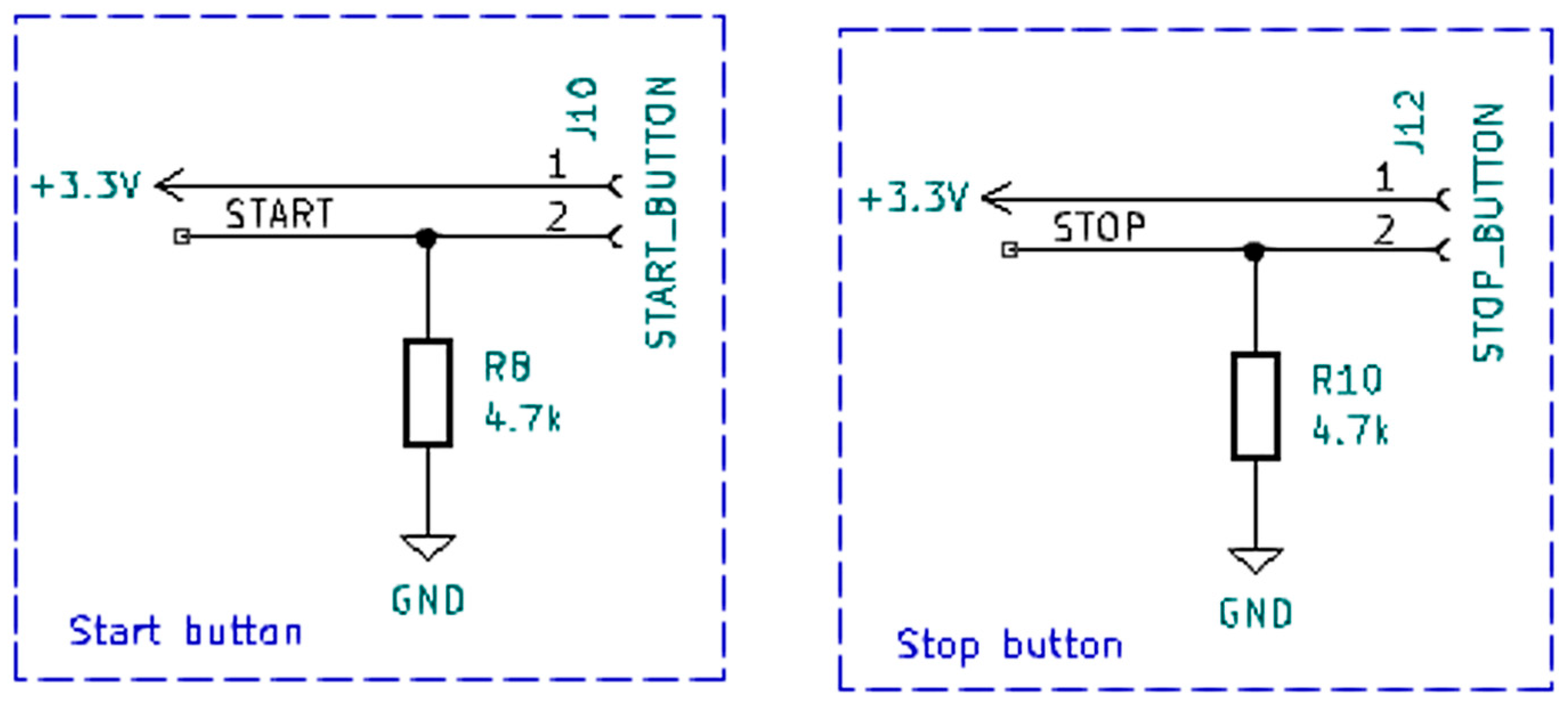
Start and stop buttons are attached to the input pins RB4 and RB5 of the MCU, respectively (see Figure 3). The buttons are of SPST (single pole–single throw) OFF–(ON) type. When a button is pressed, a high-level signal is fed to its input pin of the MCU, and the corresponding program code is executed in order to start or stop the water pump. Pull-down resistors of 4.7   k Ω have been used to prevent an undefined state at the respective MCU input pin.
  • Flow Sensor:
The flow sensor is an Adafruit YF-S201 with a measurement range of 0.3–10 L/min and a supply voltage of 5–18 V. This is a 3-wire flow sensor based on the Hall effect, which outputs pulses according to the water flow through it. The governing equation for the calculation of the water flow is F = 7.5 · Q   ± 3 % , where F is the frequency of the pulses generated by the sensor, and Q is the flow rate. In order to measure the frequency of the sensor’s output signal, a 16-bit timer 0 (TMR0) of the MCU has been adjusted to overflow every second and set an interrupt flag bit TMR0IF of the PIR0 register. The external interrupt pin RB0 has been used to count the number of pulses, setting the external interrupt flag bit INTF of the PIR0 register each time a pulse comes and executing the corresponding interrupt service routine. At the end of the time interval (1 s), the number of pulses per second is counted, which gives the frequency of the flow sensor output signal. Afterward, the flow rate and total water quantity are calculated in the software program and displayed on the TFT display.
  • TFT LCD display:
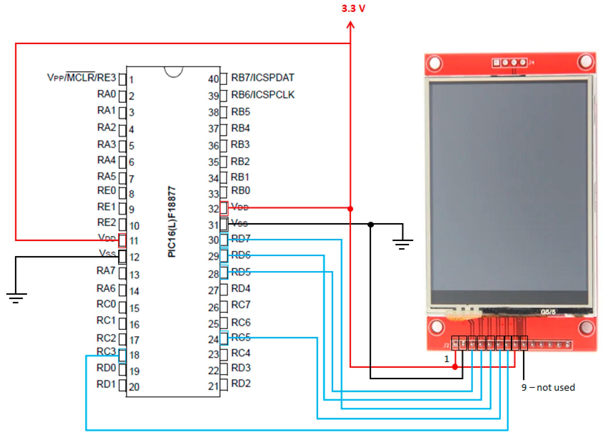
The TFT display used in this project is a 2.8-inch LCD touch screen display with 240 × 320 pixels from Adafruit. According to the datasheet, this display works with a power supply voltage in the range of 2.5 V–3.3 V [9]. The LCD display is driven by ILI9341, which is a 262,144-color single chip SOC (system-on-a-chip) driver. The logic signals should not exceed 3.3 V. The first nine pins of the display are for the display, and the other five pins are for the touch module. Communication with the microcontroller is performed using five SPI (serial peripheral interface) control/data lines: SCK (clock), MOSI (master-out slave-in), CS   (chip select), RST (reset), and D / C (data/command). Figure 4 shows the electrical connections between the MCU and the TFT display.
MCU PIC16LF18877 has two hardware SPI (MSSP1 and MSSP2) modules. In this project SPI1 module is used with SCK1 attached on pin RC3 and SDO1 (MOSI) attached on pin RC5.
  • 5 V/3.3 V power supply:
In order to supply the MCU and the flow sensor, the 12 V voltage level from the battery should be regulated at 3.3 V and 5 V, respectively. In Figure 5, the corresponding electronic circuit is shown. This is achieved with the adjustable voltage regulator IC (integrated circuit) LM317t. Adjusting potentiometers RV1 and RV2 results in the desired output voltage levels: 5 V and 3.3 V. The p-channel MOSFET IRF5305PbF is used to ensure reverse polarity protection in case the 12 V battery is connected in reverse. The diodes 1N4001 are protection diodes for the voltage regulator ICs.
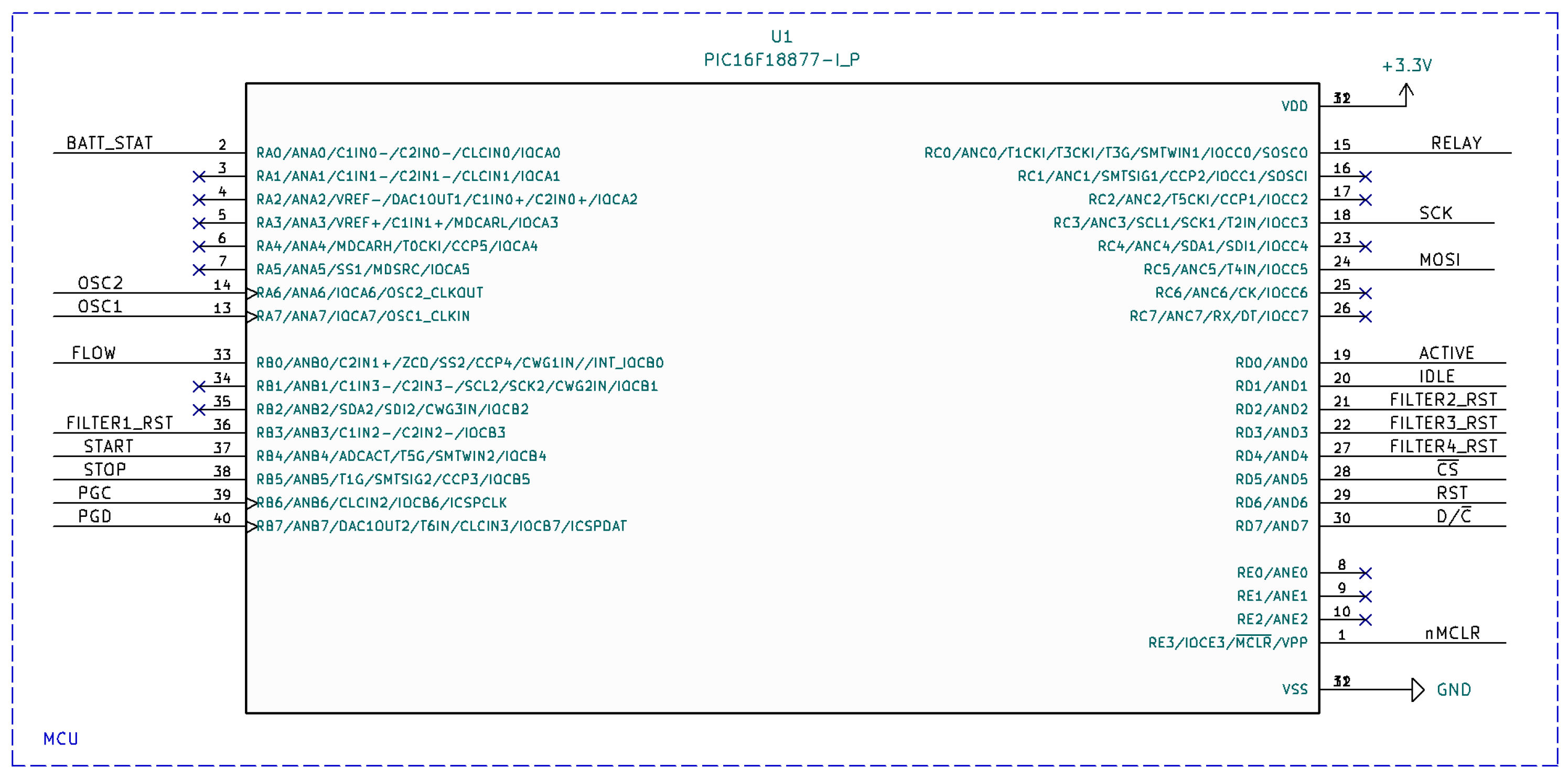
Figure 6 shows the connection scheme of the microcontroller.
Figure 7 depicts the electronic circuit diagrams of the MCU reset button and the pump drive relay.

3. System Testing and PCB Layout

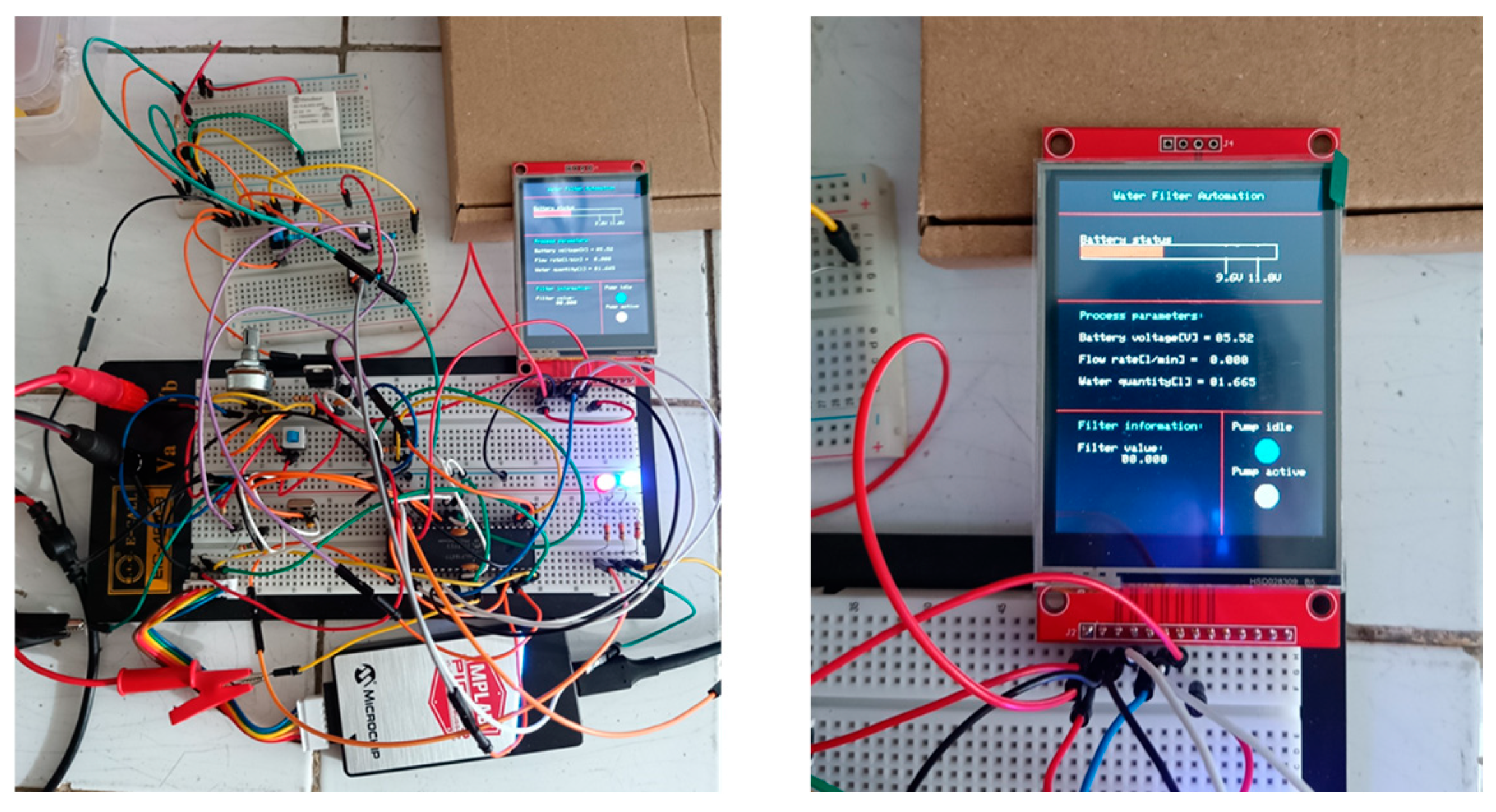
Before designing the PCB layout and building the complete device, the water filtering system was tested in a laboratory environment. The complete electronic scheme has been connected using breadboards and jump wires (as shown in Figure 8), tested, and validated. The microcontroller has been programmed with MPLAB and PicKit 5 via a 6-pin SIL (single in-line) connector using the high-voltage programming mode.
Figure 9 shows the PCB layout of the electronic control unit. The PCB design has been conducted in KiCad and is double-layered with three track sizes: 0.3 mm for signals, 0.5 mm for power signals, and 2 mm for driving the water pump through the relay. Figure 10 represents the 3D view of the PCB layout.

4. Cyber-Physical System for In Situ Treatment of River and Lake Water

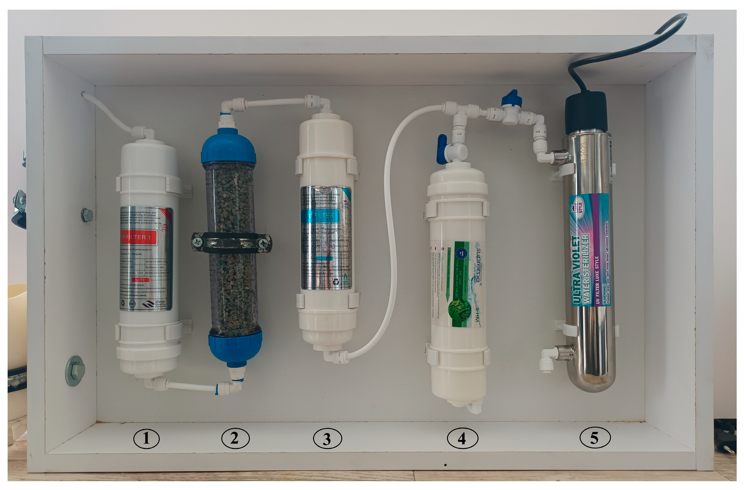
An example of a multi-stage cyber-physical system designed to improve the quality of various surface waters is presented (Figure 11). Future experimental studies on different water streams will demonstrate the system’s optimal purification efficiency. In this study, the water conditioning process is divided into two main stages: filtration and sterilization.

4.1. Filtration Stage

The first stage requires preliminary filtration [10,11], which involves the removal of mechanical impurities such as suspended solids, sediments, and other particulates that could clog the finer zeolite and activated carbon filters during initial water intake. Reducing suspended solids ensures more stable flow rates and lower pressure drops in the system—critical for battery-powered pumps and low-pressure filters. This is achieved using a linear mechanical filter (PP-1μk-QC) [12], which removes particles larger than 1 μm [13].
Subsequently, a linear zeolite filter (AIZEO) [12] containing natural zeolite (clinoptilolite type) is employed. The exceptional adsorption properties of zeolite make it highly effective for removing water contaminants [14]. It is also a cost-efficient and sustainable choice due to its ability to regenerate multiple times via backwashing with saline solutions without significant loss of performance over repeated cycles [15].
Next, filtration is performed using a linear activated carbon filter (GAC-QC-2.0) [12], made from high-quality granular coconut activated carbon. This filter removes the following:
  • Mechanical impurities (up to 5 µm);
  • Residual chlorine;
  • Heavy metal ions;
  • Organic compounds [16].
The combination of zeolite and GAC provides a broad spectrum of adsorption mechanisms: ion exchange, physical adsorption, and chemisorption. This results in significantly lower residual concentrations of toxins and organic pollutants, which is crucial for the efficiency of subsequent ultrafiltration and UV sterilization [17].

4.2. Sterilization Stage

The final step employs a UV sterilizer [12] operating at a wavelength of 205–315 nm, achieving a 99.99% disinfection efficiency [18,19]. The UV process is physical and does not require residual disinfectants (e.g., chlorine), which can form harmful byproducts. This makes the method eco-friendly and safe for end-users [19,20].
The technological scheme includes the following stages (Figure 11):
1st Stage: Filtration—the water flow passes through the following filters:
(1) Linear mechanical filter PP-1μk-QC;
(2) Linear zeolite filter AIZEO;
(3) Linear activated carbon filter GAC-QC-2.0.
2nd Stage: Ultrafiltration and UV Sterilization:
(4) Ultrafiltration membrane;
(5) UV sterilizer UV-12-W.

5. Results and Discussion

The design and evaluation of the cyber-physical system successfully demonstrated the integration of an advanced electronic control unit (ECU) with the filtration process. Key findings from the evaluation are as follows.
The system effectively monitors battery voltage levels through a voltage divider and microcontroller ADC module, ensuring stable performance while providing real-time power updates. Additionally, the Adafruit YF-S201 flow sensor has been integrated into the system, enabling precise measurement of water flow rate via pulse frequency analysis. This integration ensures accurate tracking of the total volume of filtered water, thereby assisting in the monitoring of both consumption and system efficiency. A built-in monitoring function further improves the system’s performance by alerting users when filters need to be replaced, ensuring optimal functionality over time. For user convenience, a 2.8-inch TFT LCD screen serves as the user interface, providing real-time data on battery health, water flow rate, and system alerts. The system was successfully assembled on a breadboard, tested, and validated under controlled conditions, confirming its reliability and accuracy. The compact PCB design, fabricated with a two-layer PCB layout using KiCad, ensures a space-efficient and well-organized electronic system, which contributes to the overall system’s reliability. Looking ahead, the proposed multi-stage filter system will be further improved in upcoming experiments. The focus will be on achieving a combination of filters with maximum efficiency in removing pollutants from water. Future improvements will prioritize the use of environmentally friendly and cost-effective adsorbents, with particular emphasis on the “green adsorption process”—adsorbents synthesized through environmentally friendly methods to remove harmful pollutants. Promising adsorbents like zeolites and activated carbon will be utilized, alongside macrophytes and macroalgae, which have shown potential in filtering a wide range of contaminants [16].

6. Conclusions

A smart embedded cyber-physical system with advanced monitoring and automation capabilities was successfully developed. This embedded system provides a cost-effective, energy-efficient, and automated solution for monitoring and optimizing portable water treatment processes. It shows potential for applications in river and lake water purification as well as for the precise analysis and testing of contaminated water.
The advantages of the system are as follows:
  • Water Filtration Efficiency: The system ensures a continuous and efficient filtration process, significantly improving water quality.
  • Automatic Pump Control and Real-Time Data Tracking: Automated operation and continuous monitoring of system parameters ensure optimal filtration without manual intervention.
  • Battery-Powered Design: The system is powered by a battery and utilizes optimized low-power components, making it ideal for deployment in remote locations where traditional power sources may not be available.
  • Modular ECU: The modular nature of the embedded control unit (ECU) allows for easy integration with additional sensors or wireless connectivity, enabling adaptability for IoT-based applications.
  • Future Enhancements: Potential future developments may include wireless data logging and remote-control capabilities, further improving user accessibility and convenience. Moreover, the integration of solar panels and a solar charge controller is considered an enhancement, which will improve the sustainability of the system.
The smart embedded cyber-physical system offers a versatile and efficient solution for river and lake water purification, with promising potential for future innovations and applications.

Author Contributions

All authors have accepted responsibility for the entire content of this manuscript and reviewed all the results. All authors have read and agreed to the published version of the manuscript.

Funding

The authors gratefully acknowledge the financial support of KP-06-N87/11 with the Research Fund/BG-175467353-2024-11-0287, funded by the Research Fund.

Institutional Review Board Statement

Not applicable.

Informed Consent Statement

Not applicable.

Data Availability Statement

Not applicable.

Conflicts of Interest

The authors declare no conflicts of interest.

References

  1. Mishra, R.K. Fresh water availability and its global challenge. Br. J. Multidiscip. Adv. Stud. 2023, 4, 1–78. [Google Scholar] [CrossRef]
  2. Yasmeen, R.; Khan, F.S.; Nisa, W.U.; Saleem, A.R.; Awais, M.; Jameel, M.; Dara, R.N.; Khan, M.I. Enhanced water purification by using graphene oxide nano-membranes: A novel approach for mitigating industrial pollutant. Carbon Trends 2025, 19, 100486. [Google Scholar] [CrossRef]
  3. Ejiohuo, O.; Onyeaka, H.; Akinsemolu, A.; Nwabor, O.F.; Siyanbola, K.F.; Tamasiga, P.; Al-Sharify, Z.T. Ensuring water purity: Mitigating environmental risks and safeguarding human health. Water Biol. Secur. 2024, 4, 100341. [Google Scholar] [CrossRef]
  4. Cescon, A.; Jiang, J.-Q. Filtration Process and Alternative Filter Media Material in Water Treatment. Water 2020, 12, 3377. [Google Scholar] [CrossRef]
  5. Chattopadhyay, S. Embedded System Design, 3rd ed.; PHI Learning Pvt. Ltd.: Delhi, India, 2023; ISBN 9789391818623. [Google Scholar]
  6. Marwedel, P. Embedded System Design; Springer: Cham, Switzerland, 2021; ISBN 978-3-030-60910-8. [Google Scholar] [CrossRef]
  7. Guo, C.; Yang, Z.; Chen, Y.Y. A Survey of Energy Consumption Measurement in Embedded Systems. IEEE Access 2021, 9, 60516–60530. [Google Scholar] [CrossRef]
  8. Microchip Technology Inc. Available online: https://www.microchip.com/en-us/product/pic16f18877 (accessed on 28 March 2025).
  9. Multi-Inno Technology, Co. Available online: https://www.adafruit.com (accessed on 28 March 2025).
  10. Elimelech, M.; Phillip, W.A. The future of seawater desalination: Energy, technology, and the environment. Science 2011, 333, 712–717. [Google Scholar] [CrossRef] [PubMed]
  11. Meng, F.; Li, B.; Zhang, H.; Yang, F.; Zhang, X.; Huang, X. Fouling and chemical cleaning of microfiltration membranes: A review. J. Membr. Sci. 2009, 343, 23–34. [Google Scholar] [CrossRef]
  12. Frenel Network. Available online: https://www.frenel.net (accessed on 28 March 2025).
  13. Pawar, R.; Zhang, Z.; Vidic, R.D. Laboratory and pilot-scale studies of membrane distillation for desalination of produced water from Permian Basin. Desalination 2022, 537, 115853. [Google Scholar] [CrossRef]
  14. Velarde, L.; Nabavi, M.S.; Escalera, E.; Antti, M.-L.; Akhtar, F. Adsorption of heavy metals on natural zeolites: A review. Chemosphere 2023, 328, 138508. [Google Scholar] [CrossRef]
  15. Senila, M.; Cadar, O. Modification of natural zeolites and their applications for heavy metal removal from polluted environments: Challenges, recent advances, and perspectives. Heliyon 2024, 10, e25303. [Google Scholar] [CrossRef]
  16. Liu, X.; Li, Z.; Orbell, J.D.; Dow, N. Impact of granular activated carbon pretreatment on ultrafiltration membrane fouling. Desalination 2017, 401, 32–42. [Google Scholar] [CrossRef]
  17. Feng, Y.; Lau, S.S.; Mitch, W.A.; Russell, C.; Pope, G.; Gu, A.Z. Impacts of disinfection methods in a granular activated carbon (GAC) treatment system on disinfected drinking water toxicity. J. Hazard. Mater. 2025, 490, 137737. [Google Scholar] [CrossRef] [PubMed]
  18. Hijnen, W.A.M.; Beerendonk, E.F.; Medema, G.J. Inactivation credit of UV radiation for viruses, bacteria and protozoan (oo) Cysts in water: A review. Water Res. 2006, 40, 3–22. [Google Scholar] [CrossRef] [PubMed]
  19. Timmermann, L.F.; Ritter, K.; Hillebrandt, D.; Küpper, T. Drinking water treatment with ultraviolet light for travelers–Evaluation of a mobile lightweight system. Travel Med. Infect. Dis. 2015, 13, 466–474. [Google Scholar] [CrossRef] [PubMed]
  20. Afkhami, A.; Marotta, M.; Dixon, D.; Ternan, N.G.; Montoya-Jaramillo, L.J.; Hincapie, M.; Galeano, L.; Fernandez-Ibanez, P.; Dunlop, P.S.M. Assessment of low-cost cartridge filters for implementation in household drinking water treatment systems. J. Water Process Eng. 2021, 39, 101710. [Google Scholar] [CrossRef]
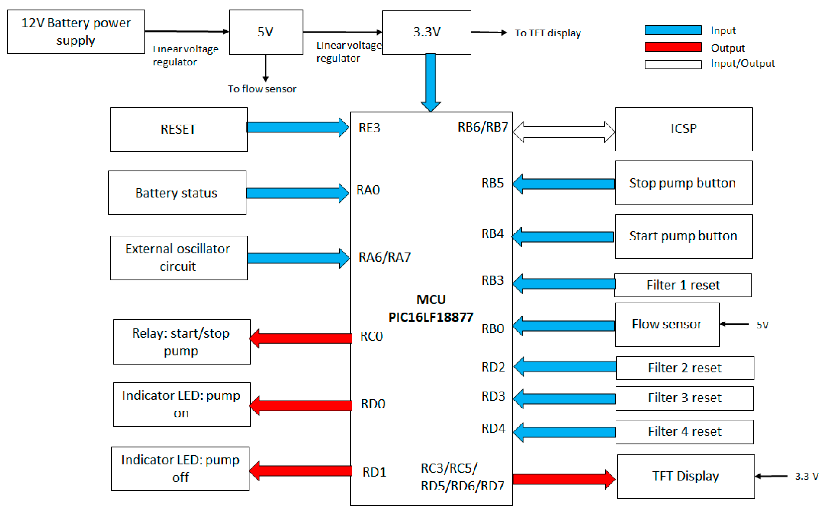
Figure 1. Block scheme of electronic control.
Engproc 104 00065 g001
Figure 2. External 4 MHz crystal oscillator.
Engproc 104 00065 g002
Figure 3. Start–stop buttons circuit diagrams.
Engproc 104 00065 g003
Figure 4. Connections between the MCU and the TFT display.
Engproc 104 00065 g004
Figure 5. The 3.3 V/5 V power supply schematic.
Engproc 104 00065 g005
Figure 6. MCU connection scheme.
Engproc 104 00065 g006
Figure 7. Reset button and pump relay schematics.
Engproc 104 00065 g007
Figure 8. Laboratory test and TFT display.
Engproc 104 00065 g008
Figure 9. PCB layout.
Engproc 104 00065 g009
Figure 10. PCB layout 3D view.
Engproc 104 00065 g010
Figure 11. Components of a cyber-physical system for in situ treatment of river and lake water: 1—linear mechanical filter PP-1μk-QC; 2—linear zeolite filter AIZEO; 3—linear activated carbon filter GAC-QC-2.0; 4—ultrafiltration membrane; 5—UV sterilizer UV-12-W.
Engproc 104 00065 g011
Disclaimer/Publisher’s Note: The statements, opinions and data contained in all publications are solely those of the individual author(s) and contributor(s) and not of MDPI and/or the editor(s). MDPI and/or the editor(s) disclaim responsibility for any injury to people or property resulting from any ideas, methods, instructions or products referred to in the content.