1. Introduction
Cars with an internal combustion engine (ICE) have a lower price and a longer range than electric cars, they charge much faster, and there is an established network of gas stations. On the other hand, they are noisier, emit CO2, NOx, particulate matter and other harmful substances into the atmosphere, and ICE failures are much more common and require higher operating costs (fuel, oils, filters, repairs).
Electric cars are excellent in cities because of their quietness, zero emissions and efficiency when stopping and starting. They do not idle the motor at intersections and use regenerative braking to return energy to the battery during deceleration. Urban driving reduces energy consumption compared to travelling outside the city, where aerodynamic drag increases [
1,
2]. Typically, an urban electric car only needs a range of 50–100 km, so a large battery is not necessary—a 5–20 kWh battery is often sufficient, as seen in models such as the Citroen Ami, Renault Twizy, and Smart.
This paper presents a methodology for converting ICE-powered cars into efficient electric vehicles suitable for urban use. In contrast to the traditional selection based solely on the low mass of the vehicle, the most suitable car for conversion is sought, which also provides a minimal air resistance and a suitable layout. An attempt is also made to find the most appropriate formation for an electric vehicle (disposition of parts, formal structure or arrangement, etc.).
2. Methodology for Selecting a Car for Conversion
Several basic criteria that should be taken into account when choosing a car for conversion can be systematized.
2.1. Dimensions
The purpose of the conversion is to develop an electric car to transport people and small loads in urban conditions. It must be compact, light, and convenient for movement in the urban environment, considering the limited parking space in central city areas. The car used for conversion must be small in order to be convenient in the city.
2.2. Mass
It is important for an electric car to consume minimal energy for propulsion, not only for economic reasons, but also in relation to the energy reserve in the battery. With less mass, an electric car will have lower energy consumption and a longer range [
1,
2,
3,
4,
5,
6,
7].
2.3. Air Resistance
For energy consumption and the distance travelled, in addition to the mass of the electric car, the air resistance of the vehicle is also important. Although speeds in urban conditions are low, air resistance also matters, since any excessive energy consumption affects the range. Most often, compact city cars, relatively short and tall, have relatively poor aerodynamic performance, and therefore for conversion, it is best to choose a car that, in addition to its small size and weight, also has good aerodynamics [
3,
7].
2.4. Drivetrain Layout (Configuration)
In contemporary electric cars, designed from the ground up as electric vehicles (Tesla, VW ID, etc.), rear-wheel drive with a central or rear-mounted electric motor is the preferred solution. This drive scheme allows better utilization of the motor power when accelerating and climbing steep slopes. Unlike cars with ICEs, electric cars with such a drive provide sufficient space for rear seats or a trunk above the compact electric motor. Electric cars with this drive have excellent cross-country ability on all types of surfaces, regardless of the number of passengers and their luggage.
Thus, cars with a central or rear-mounted motor driving the rear wheels are very suitable for converting into an electric car.
3. Case-Study on Electric Conversion of a Small City Car
3.1. Technical Parameters of the Designed Electric Car
The technical specifications for the converted electric car include the following requirements:
Range on one charge—at least 50 km;
Maximum speed—at least 50 km/h;
Maximum slope to be overcome when climbing—at least 20%;
Average acceleration to reach 50 km/h—at least 1 m/s2;
Traction electrical drive—three-phase induction motor and inverter controller with vector control—most commonly used as a traction drive [
8,
9,
10].
3.2. Selecting a Car for Conversion
A car that meets the technical requirements listed in
Section 2 is the Smart Fortwo, which is characterized by the following parameters [
8,
9,
10,
11]:
Dimensions: Length 2.50 m, width 1.50 m. The Smart Fortwo car is known for its compactness and maneuverability, which makes it extremely convenient for driving and parking in an urban environment. The frontal area is S = 1.95 m2.
Mass: Low mass: m = 730 kg.
Air resistance: The coefficient of aerodynamic drag Cd is low (compared to most city cars): Cd = 0.35.
Drivetrain layout: This car has a rear engine and rear-wheel drive, which increases the interior space and improves the maneuverability, traction, and cross-country ability of the vehicle, thus it is very suitable for conversion into an electric car.
3.3. Component Placement
The battery is placed in the floor under the two seats of the car. The traction force will be provided by a three-phase induction motor, instead of an internal combustion engine, driving the rear wheels, while retaining the original gearbox [
4]. The motor is controlled by an inverter controller to convert the voltage from the battery into a sinusoidal one and to regulate the speed and torque of the motor. Preserving the gearbox expands the torque and speed range of the drive wheels and optimizes the operation of the electric motor.
3.4. Calculations for Uniform Horizontal Movement
3.4.1. Acting Forces
The required traction force of the driving wheels
Fw during uniform movement on a horizontal road must overcome the total resistance force
Ft for this movement and, accordingly, be equal to it:
The total resistance force
Ft is the sum of the rolling resistance force
Fr and the aerodynamic drag force
Fd:
The rolling resistance force Fr depends on the resistance coefficient f0 of the corresponding road surface (for asphalt, average value is f0 = 0.015) and on the speed of movement (at a speed over 60 km/h):
where
G is the weight of the electric vehicle;
g—the acceleration due to gravity; m—mass of the electric vehicle.
where
V is the speed of the electric vehicle.
The aerodynamic drag force
Fd is determined by the following relationship:
where
S is the frontal area of the electric vehicle (S = 1.95 m
2);
—air density ( = 1.22 kg/m3);
Cd—coefficient of aerodynamic drag (Cd = 0.35).
The total resistance force
Ft has been calculated at different speeds (from 10 km/h to 110 km/h) according to Equations (2) ÷ (5), as well as at different loads–with driver only and maximum mass. The obtained values are systematized in
Table 1, columns 2 and 3.
3.4.2. Required Power
The required power of the driving wheels
Pw can be calculated from the required traction force
Fw [
3], which is equal to
Ft:
The results obtained for the power
Pw at different speeds and loads are shown in
Table 1, columns 4 and 5.
The required power of the electric motor
Pm is
where
is the efficiency of the transmission (
= 0.95) [
4].
The required motor power
Pm has also been calculated at different speeds and loads at the values are shown in
Table 1, columns 6 and 7.
Since extra-urban driving may sometimes be required and a power reserve is needed, an induction motor with a nominal power of 7.5 kW was selected, sufficient, according to the results in
Table 1, for a speed of almost 80 km/h. The data for the selected motor are shown in
Table 2 [
12]. The two-minute power is 19 kW and can be used for acceleration and climbing slopes—it is sufficient for a maximum short-term speed of about 110 km/h. The motor is designed for frequency control and specifically for installation in electric vehicles.
The advantages of this type of motor include its high reliability in operation and long life, increased efficiency and energy saving, low noise and vibration levels, and it also meets the requirements for electromagnetic compatibility according to contemporary IEC standards.
The values of the power consumed by the batteries
Pel for movement at a certain speed have also been calculated and are shown in
Table 1, columns 8 and 9:
where
is the total efficiency of the motor and the controller [
12].
3.5. Electric Car Energy Consumption and Range
The energy consumption
E per 100 km is determined by the formula:
The obtained values are shown in
Table 1, columns 10 and 11.
Therefore, the range
Smax of the electric car can be calculated using the expression:
where
CB is the battery capacity.
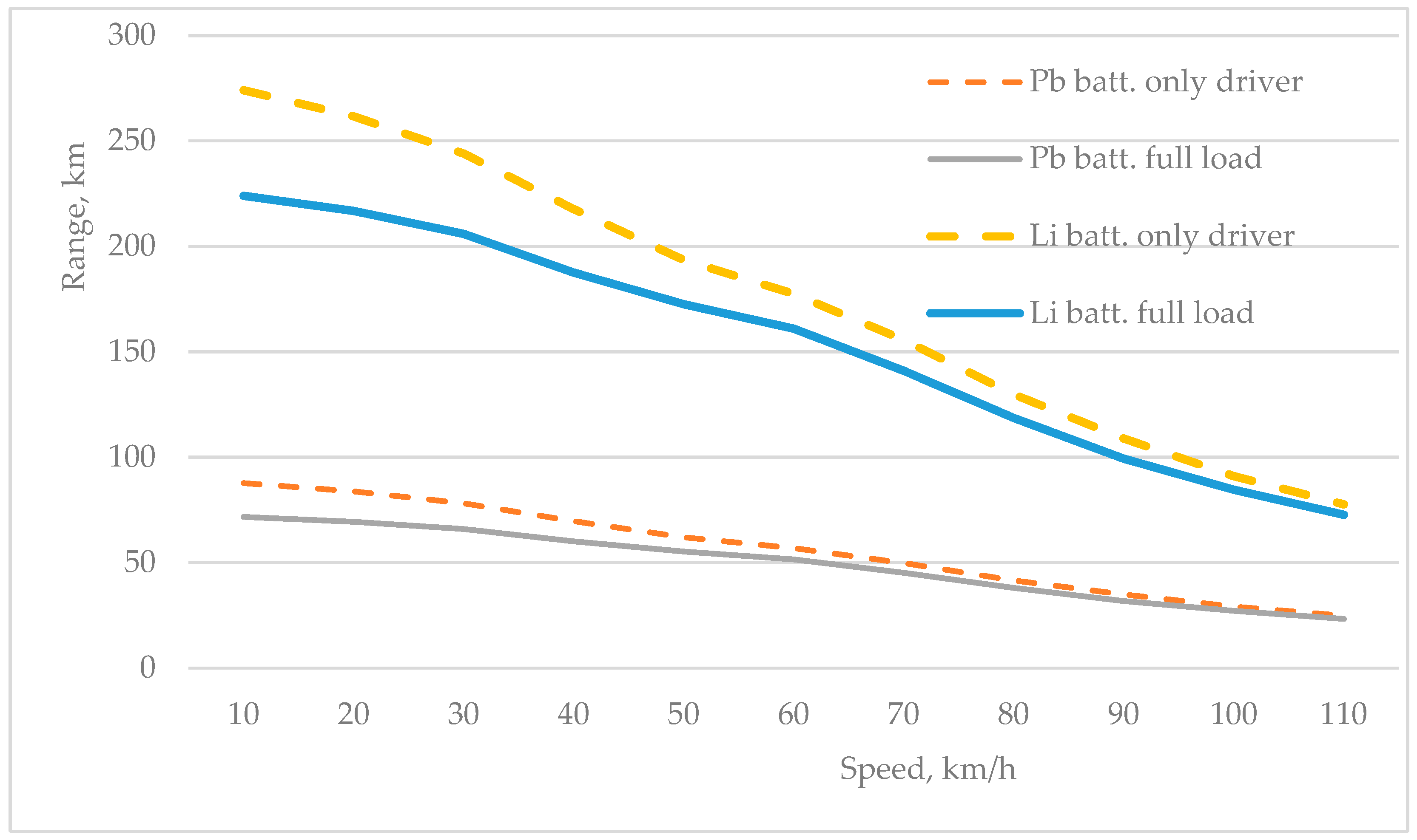
The range is also calculated at different speeds and loads for two types of batteries—using budget lead (Pb) batteries or LiFePO4 batteries with the same mass m
batt = 90 kg. The obtained values are shown in
Table 1, columns 12 ÷ 15.
The values for energy consumption
E per 100 km and range
Smax for speeds of 80 km/h and above are in parentheses in
Table 1 because they only matter as momentary values—the car cannot be driven continuously with power above the rated motor power.
The range versus speed relationships are shown graphically in
Figure 1 for four cases according to the battery used and the payload. It is evident that the range increases significantly if LiFePO4 batteries are used.
3.6. Climbing a Slope
When the car climbs a slope with an angle α, an additional resistance force
Fi from the slope appears due to gravity.
This is the component of the gravity force
G, which is parallel to the road surface and directed against the movement of the car. The other component of the gravity force is
G.cosα, which is perpendicular to the road surface—it creates the load on the wheels and causes the deformation of the tyres and a change in their resistance. This is the rolling resistance force on a slope with an angle α:
The slope
p of a road section is measured as the ratio of its height to its length:
By substituting Equation (13) into Equation (12), the dependence of the resistance force on the slope is determined by the following expression:
The resistance force on the road
when climbing is the sum of the two forces:
At the maximum climb slope, the maximum traction force
Fwm of the drive wheels must be greater than the road resistance force when climbing
. The maximum traction force
Fwm of the drive wheels is calculated by the maximum (peak) torque
Mmm of the induction motor of the electric vehicle and depends on the gear ratio
of the engaged gear and the efficiency of the transmission
:
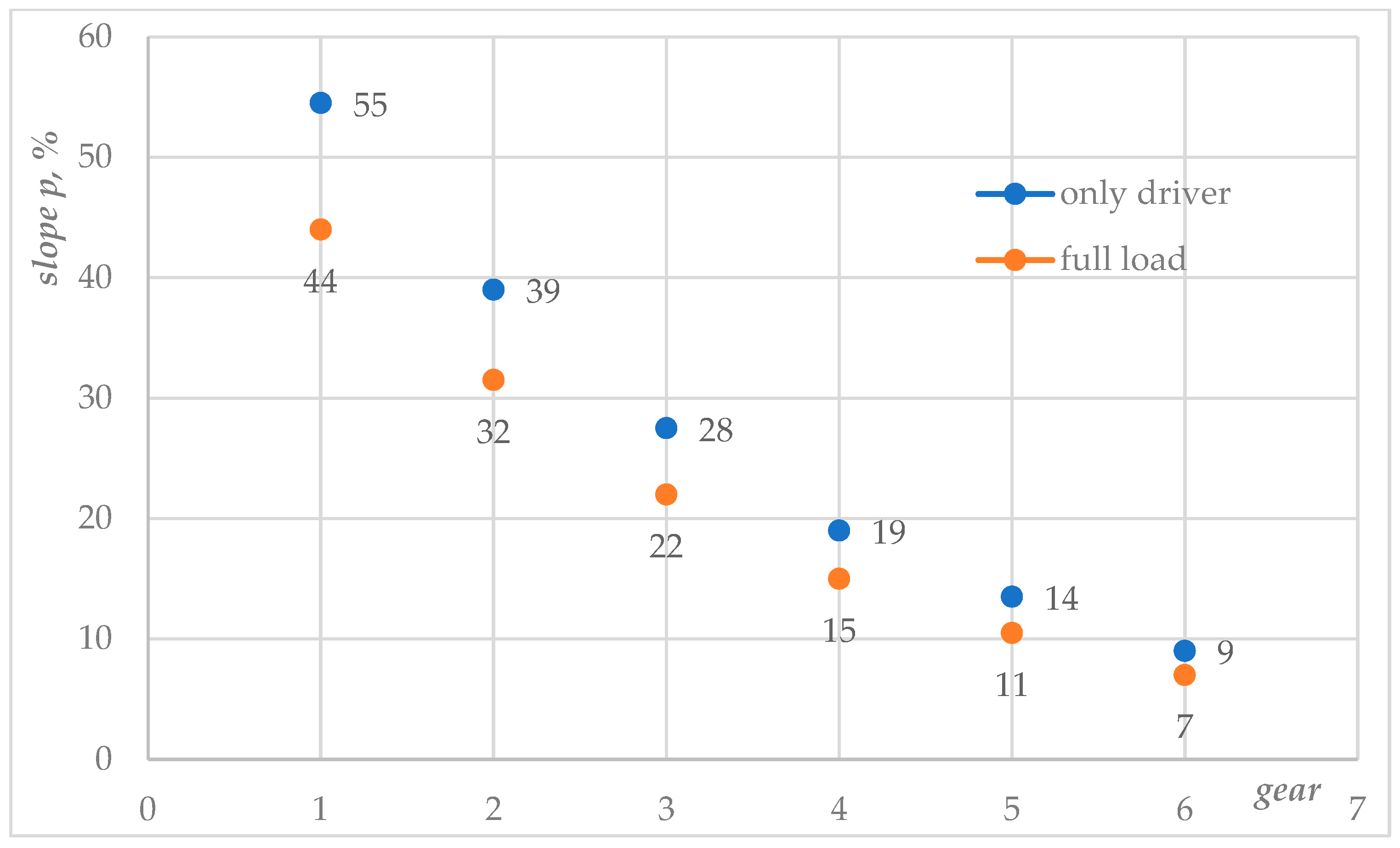
The obtained values for the maximum climbed slope with only a driver and with full load in the different gears are systematized in
Table 3 and shown graphically in
Figure 2. In
Table 3, they are compared with the maximum traction force
Fwm and the resistance force
FΨ.
The obtained values for the overcome slope when climbing satisfy the technical requirements set for the parameters of the designed electric vehicle—a slope of 20% can be climbed even in third gear at full load, and in first gear a slope of over 40% can be overcome.
3.7. Dynamic Mode—Acceleration of the Electric Car
Acceleration shows how fast the electric car increases its speed over time. Acceleration
a is the change in speed Δ
V occurring in a time interval Δ
t:
During acceleration, the traction force
from the electric motor is greater than the total resistance force
caused by rolling resistance force and air resistance force. The difference between the traction force
and the total resistance force
constitutes the accelerating force
Fa. The acceleration
a of an electric car is directly proportional to the accelerating force
Fa, but is also inversely proportional to its mass
m:
The acceleration time
tacc from
V = 0 to
V = 50 km/h in third gear has been calculated by dividing this speed interval into small intervals of 10 km/h Δ
V. The average total resistance force
Ft has been calculated for each interval. The traction force
Fw has been determined from the maximum torque of IM (
Mmm = 108 Nm), but only up to a speed allowing operation at maximum motor power (19 kW)—this is the speed of 30 km/h of the electric car. With a further increase in vehicle speed and, accordingly, motor speed, the maximum torque decreases proportionally so as to not exceed the maximum power. Therefore, at speeds above 30 km/h, for the last two speed intervals, the acceleration time has been calculated using the average tractive force corresponding to the average motor torque for each interval. Considering Equations (2), (3), (5), (17) and (18), the following expression has been used:
where
are small time intervals corresponding to the speed intervals Δ
V;
Vavi—average value of
V in the
ith interval;
n—number of speed intervals;
a(
Vi)—acceleration at the average value of
V in the
ith interval.
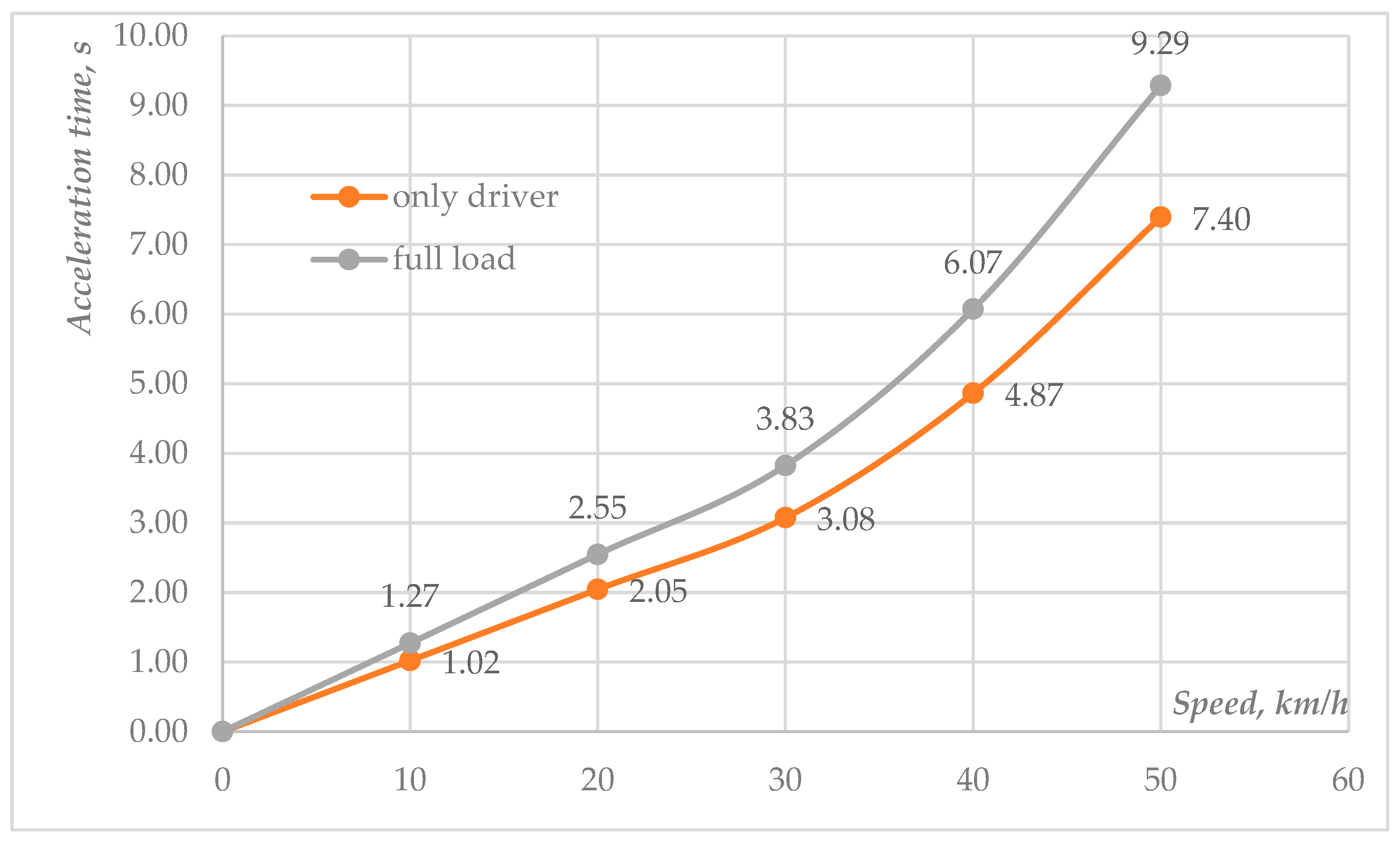
For all five speed intervals of 10 km/h, the acceleration time
tacc has been calculated at different loads and is shown graphically in
Figure 3. These intervals are then summed to find the total acceleration time in the speed ranging from 0 to 50 km/h.
From the total acceleration time, the average acceleration from 0 to 50 km/h can be found using Equation (17). The obtained values for acceleration
a and acceleration time
Δt for each speed interval (from
V1 to
V2) are systematized in
Table 4.
The obtained values for the acceleration satisfy the technical requirements set for designing an electric car and the average acceleration to reach 50 km/h is greater than 1 m/s2.
4. Conclusions
The report presents a methodology for selecting and converting a small city car into an electric vehicle. For the energy source in the electric car, two options are offered—a budget solution with 4.8 kWh lead batteries (with which the range obtained at a speed of 50 km/h is 55–62 km, depending on the load) and 15 kWh lithium–iron–phosphate batteries with the same mass m = 90 kg (the range can be increased more than three times, up to 194 km). With the necessary power reserve and ensuring the ability to drive outside the city, an induction motor with a nominal power of 7.5 kW (maximum 19 kW) was chosen to drive the electric car. In this way, the calculated maximum permanent speed of the electric vehicle in a horizontal section is almost 80 km/h, and for a short time it reaches 110 km/h.
Due to the high maximum motor torque of 108 Nm and the retention of the six-speed gearbox, very good results were obtained for the maximum slope overcome by the electric car: 44% in first gear with a full load and 55% with only the driver.
The calculated average acceleration to 50 km/h in third gear is higher than the minimum set—from 1.5 to 1.9 m/s2 depending on the load.
Therefore, the proposed methodology for selecting a car for conversion, designing the drivetrain, and placing the components provides an opportunity to develop an efficient electric vehicle for driving mainly in the city, but also with the possibility of a relatively long range in a non-urban environment, climbing steep slopes and a sufficiently good dynamic performance.
Author Contributions
Conceptualization, methodology, software, formal analysis, investigation, resources, data curation, writing—original draft preparation, A.N.; writing—review and editing, validation, visualization, supervision, project administration, funding acquisition, V.D. All authors have read and agreed to the published version of the manuscript.
Funding
This research received no external funding.
Institutional Review Board Statement
Not applicable.
Informed Consent Statement
Not applicable.
Data Availability Statement
No new data were created or analyzed in this study.
Conflicts of Interest
The authors declare no conflicts of interest.
Abbreviations
The following abbreviations are used in this manuscript:
| ICE | internal combustion engine |
| IM | induction motor |
References
- Larminie, J.; Lowry, J. Electric Vehicle Technology Explained; John Wiley & Sons Ltd.: New York, NJ, USA, 2003. [Google Scholar]
- Evtimov, I.; Ivanov, R. Electric Vehicles; University of Ruse: Ruse, Bulgaria, 2016. [Google Scholar]
- Balgaranov, L. Electric Transport; University of Sofia: Sofia, Bulgaria, 2009. [Google Scholar]
- Ersoy, M.; Gies, S. Fahrwerkhandbuch; ATZ/MTZ-Fachbuch; Springer Vieweg: Wiesbaden, Germany, 2017. [Google Scholar]
- Barlow, T.J.; Latham, S.; McCrae, I.S.; Boulter, P.J. A Reference Book of Driving Cycles for Use in the Measurement of Road Vehicle Emissions; V. 3; TRL Limited: Thiruvananthapuram, Kerala, India, 2009. [Google Scholar]
- E/ECE/TRANS/505/Rev.2/Add.100/Rev.3. Available online: https://unece.org/transport/documents/2022/03/standards/regulation-no-100-rev3 (accessed on 23 March 2025).
- Vehicle Regulations, UNECE Transport Division. Available online: http://www.unece.org/trans/main/welcwp29.html (accessed on 23 March 2025).
- Hughes, A. Electric Motors and Drives—Fundamentals, Types and Applications, 3rd ed.; Elsevier Ltd.: Amsterdam, The Netherlands, 2006. [Google Scholar]
- Bakshi, U.; Bakshi, M. Electrical Drives and Control; Technical Publications: Pune, India, 2009. [Google Scholar]
- Boldea, I.; Nasar, A. Electrical Drives; CRC/Taylor & Francis Group: New York, NY, USA, 2006. [Google Scholar]
- Car Specifications Database. Available online: https://www.auto-data.net/bg (accessed on 23 March 2025).
- Induction Motor Type GEV1041MA—Technical Specification; Foshan Shunde Green Motor Technology Co. Ltd.: Foshan, China, 2023.
| Disclaimer/Publisher’s Note: The statements, opinions and data contained in all publications are solely those of the individual author(s) and contributor(s) and not of MDPI and/or the editor(s). MDPI and/or the editor(s) disclaim responsibility for any injury to people or property resulting from any ideas, methods, instructions or products referred to in the content. |
© 2025 by the authors. Licensee MDPI, Basel, Switzerland. This article is an open access article distributed under the terms and conditions of the Creative Commons Attribution (CC BY) license (https://creativecommons.org/licenses/by/4.0/).


