Abstract
The increasing demand for high-speed internet and advanced digital services necessitates the deployment of robust and scalable broadband infrastructure, particularly in smaller urban and rural areas. This paper presents the design and implementation of a passive optical network (PON) based on a gigabit-capable passive optical network (GPON) standard to deliver fiber-to-the-home (FTTH) services in a small-town setting. The proposed solution prioritizes cost-effectiveness, scalability, and minimal energy consumption by leveraging passive splitters and unpowered network elements. We detail the topology planning, splitter architecture, installation practices, and technical specifications that ensure efficient signal distribution and future network expansion. The results demonstrate the successful implementation of an optical access infrastructure that supports high-speed internet, Internet Protocol television (IPTV), and voice services while maintaining flexibility for diverse urban layouts and housing types.
1. Introduction
In recent years, the demand for data rates for consumer communication needs has increased significantly. Fifth-generation (5G) mobile radio access networks provide a solution to these high bandwidth requirements, and are expected to provide users with low latency, high data rates, and ubiquitous access [1]. However, 5G requires network densification to meet ambitious capacity targets [2].
Broadband client access, supporting data rates of tens of Mbit/s, is expected to be based on optical transmission. Generally, most customers connect to the nearest central office (CO) with twisted copper wires. In order to achieve broadband connectivity, the wires are replaced or supplemented with fiber optic cables.
Nowadays, research is constantly being conducted on various options for providing optical transmission, because the process of building a new infrastructure is expensive. Therefore, optimal solutions are being sought to ensure efficient optical transmission [3].
The popular point-to-point concept is a communication approach used in systems such as Synchronous Digital Hierarchy (SDH) and Ethernet. Passive optical networks (PON), including Ethernet PON (E-PON) and broadband PON (B-PON), are technologies that enable significant streamlining of the physical network infrastructure, leading to a reduction in maintenance costs [4]. PON standardization is still evolving and the terminology may vary depending on the context. PONs can be considered to be optical access networks/optical feeder/optical distribution networks depending on the optical signal’s transmission [5].
The purpose of this article is to present the design, implementation, and evaluation of a fiber-to-the-home (FTTH) access network based on a gigabit-capable passive optical network (GPON). The purpose of this study is to present a way to build optical connectivity to any private home, commercial or industrial facility, with minimal costs, and to provide high-speed internet and IP Television.
An FTTH network is a cost-effective and profitable solution based on passive technology. Compared to copper wires, optical fiber has almost infinite bandwidth and, at the same time, increases network performance [6,7].
The remainder of this paper is organized as follows. Section 2 reviews the fundamental technologies and standards relevant to PON and GPON systems. Section 3 presents the design methodology, including service analysis, traffic modeling, topology selection, and optical budget calculations, which form the basis for network planning. Section 4 discusses the implementation results, highlighting technical procedures, infrastructure layout, and installation practices. Finally, Section 5 concludes this study and outlines directions for future development and expansion of the network.
2. Technologies
To achieve the goal of this study PON technologies were used [6]. A PON is a network that transports data in an optical domain between an optical line terminal (OLT) and an ONU (optical network unit) or ONT (optical network terminal) (G.984.1) [8,9]. Through the PON network, an optical distribution network (ODN) can be built. It carries out optical data transmission from an OLT to multiple user terminal devices (ONU) [10].
Three PON schemes are well known, differing in the fiber termination point. Fiber-to-the-curb (FTTC) technology provides broadband, plain old telephone service (POTS), integrated services digital network (ISDN), and shared access with digital subscriber line (DSL) services. The fiber-to-the-building (FTTB) scheme offers similar services to multi-dwelling units (MDUs) and provides private services to businesses. Fiber-to-the-home (FTTH) concepts delivers broadband, POTS, and ISDN directly to individual homes [10,11].
PON research focuses on the following two areas: the Ethernet First Mile Alliance (EFMA)/Institute of Electrical and Electronics Engineers (IEEE) definition based on Ethernet PONs and the Full Service Access Network (FSAN)/International Telecommunication Union (ITU-T) definition based on ATM and GFP PONs [12,13,14,15].
A PON uses wavelength-division multiplexing (WDM) to provide full duplex operation over a single non-zero dispersion-shifted fiber (ITU-T G.652). Typically, data is transmitted to the customer at 1490 nm, and back in the opposite direction at 1310 nm, and a signal with a wavelength of 1555 nm may be used for an additional service, such as cable television.
Our research is based on the Ethernet standard 8.3, E-PON 802.3ah, which defines a similar passive network with a range of up to 20 km. It uses frequency division multiplexing of the same optical frequencies as a GPON and time-division multiple access (TDMA) [16]. In this case, the speed is 1.25 Gbits/s simultaneously on the forward and reverse channels, which is also known as the Gigabit Ethernet PON (GEPON). There is also a 10-Gbit/s Ethernet (10 GbE) version—802.3av with a line speed of 10.3125 Gbits/s and 10G EPON (10 Gb/s downstream, 1 and 10 Gb/s upstream).
3. Methodology
3.1. Service Requirements and Bandwidth Estimation
To design the GPON-based FTTH network, we first identified the target user services and their bandwidth needs. In a typical small-town deployment, residential subscribers demand a mix of high-speed Internet, Internet Protocol television (IPTV), and Voice over IP (VoIP) telephone services (i.e., a triple-play offering). We assumed each household may utilize multiple IPTV streams, one or more VoIP lines, and general internet access simultaneously during peak hours. Table 1 summarizes the service profile considered per user, and the estimated bandwidth requirements for each service, based on industry guidelines and standards.

Table 1.
Typical user service profiles and bandwidth requirements per subscriber.
Each IPTV stream (e.g., a live HD channel) was budgeted at around 5–8 Mbit/s, and we allowed for up to 2 simultaneous HD streams per home (for multiple TVs). For 4K UHD content, a single stream can demand ~20 Mbit/s, so homes with 4K service would consume more bandwidth (we assumed such cases are a smaller fraction of users). VoIP lines consume relatively negligible bandwidth (≈0.1 Mbit/s per call) but were included to account for phone service. The remaining bandwidth is for general internet usage (web, video streaming, gaming, etc.), which we dimensioned according to the subscriber’s service tier (e.g., 50 Mbps or 100 Mbps plan). In summary, a typical peak usage scenario per household might involve two HD IPTV streams (~10–12 Mbps total), one active VoIP call (~0.1 Mbps), and concurrent internet use (which could range up to the subscribed downstream rate). This yields an aggregate peak demand per user on the order of tens of Mbps (e.g., 50+ Mbps in the worst case for a heavy-use household). These service demand values are in line with real-world FTTH triple-play deployments and provide the basis for network dimensioning.
3.2. Traffic Aggregation and PON Dimensioning
Using the above service profile, we next calculated the aggregate bandwidth demand on each segment of the PON. The GPON standard provides a total downstream capacity of 2.488 Gbps (and 1.244 Gbps upstream) per PON port [17]. This capacity is shared by all users on that PON in a point-to-multipoint fashion. We considered a conservative worst-case scenario where many users are simultaneously active at peak rates, as well as more realistic typical usage scenarios. In a worst-case scenario, for example, 32 subscribers each using 100 Mbps (e.g., multiple video streams plus data) would amount to an aggregate demand of 3.2 Gbps, which exceeds the 2.488 Gbps GPON downstream capacity. However, such synchronization of peak usage is highly unlikely in practice. Instead, network planning relies on statistical multiplexing and an oversubscription ratio—not all users will utilize their maximum bandwidth at the same time [18]. For instance, if 32 users each have up to 100 Mbps service, empirical studies show the actual concurrent usage might only reach ~75% of the GPON capacity or less [18]. In one real deployment, over 80% of subscribers subscribed to 10–20 Mbps plans, and the measured GPON port utilization stayed below 75% [18], indicating significant headroom. This justifies designing with a moderate oversubscription (e.g., on the order of 1.3–2×) to efficiently use the fiber capacity.
We dimensioned each PON segment such that the expected peak aggregate traffic remains at or below the GPON throughput, with some safety margin. Table 2 illustrates the traffic aggregation for the model PON segment in our design. In this example, a two-tier splitting architecture is assumed (details on splitters are in the next section), with 16 users per splitter in a building and 64 users on the entire PON port. Even if each user averages around 10 Mbps (e.g., one HD stream or heavy web use) during the busy hour, the total downstream traffic would be ~160 Mbps on each 1:16 splitter leg and ~640 Mbps at the OLT for 64 users. This is well below the 2488 Mbps GPON capacity (about 26% utilization), leaving a substantial margin for occasional bursts where some users hit higher rates. In a more extreme case, where each of the 64 users pulls ~39 Mbps concurrently (summing to ~2.5 Gbps), the GPON downstream link would just reach saturation; but the probability of all users sustaining such high throughput simultaneously is very low. We also ensured the upstream dimensioning (1.244 Gbps total) can accommodate typical upload demands, which are generally much lower per user (even 4K video upstream or heavy cloud backup are a fraction of download traffic). The GPON dynamic bandwidth allocation (DBA) mechanism further helps manage and prioritize bandwidth sharing among ONTs.
Table 2.
Typical network segments, split ratios, number of users, assumed average active traffic and aggregated bandwidth.
As shown in Table 2, under typical conditions the GPON throughput exceeds the actual demand and, even if demand rises (more users or higher usage per user), the network can accommodate it up to the engineered limits. For our design, we targeted a maximum of 64 users per GPON port. In the context of 32 users per PON, the aggregate demand is naturally lower (e.g., 32 × 50 Mbps = 1600 Mbps, about 64% of capacity). With 64 users, the system operates with a higher oversubscription (e.g., 64 × 50 Mbps = 3200 Mbps potential, requiring statistical sharing of the 2488 Mbps). This level of oversubscription (~1.3:1 for 50 Mbps tiers) is within acceptable bounds for GPON networks, given typical user behavior [18]. Additionally, the use of IP multicast for IPTV means that popular live channels are delivered once on the downlink and replicated to users at the splitters or ONTs, substantially reducing duplicate traffic when multiple homes watch the same channel. This multicast efficiency further lowers the effective bandwidth demand on the PON for IPTV services. Thus, by carefully planning the service mix and factoring in realistic usage patterns, the GPON downstream (2.5 Gbps) and upstream (1.25 Gbps) capacity was deemed sufficient for the small town’s peak aggregated traffic.
3.3. Topology Selection (Point-to-Multipoint Tree)
Based on the service and traffic analysis, we adopted a point-to-multipoint tree topology for the access network. In this GPON FTTH architecture, each optical line terminal (OLT) port in the central office feeds a single fiber that is split to serve multiple optical network units (ONUs/ONTs) at subscriber premises. This topology was chosen over a point-to-point fiber design for reasons of cost and scalability—a P2MP PON significantly reduces the amount of fiber and central office transceivers needed by sharing one trunk fiber among many users. The trade-off is that the 2.5 Gbps/1.25 Gbps bandwidth is shared but, as shown above, this shared capacity is sufficient for the aggregate demand. The traffic and service profile of the users (largely bursty internet traffic and streaming, with intermittent peak usage) aligns well with a TDM shared medium solution. GPON’s MAC layer and dynamic bandwidth allocation allow multiple users to efficiently share the common fiber while meeting their individual quality of service needs. In practice, PON technology streamlines the physical network by eliminating active electronics in the field and using passive splitters, which lowers maintenance costs and power consumption. Given the small-town geography, a tree topology with splitters located near clusters of users (neighborhoods or buildings) was ideal to reach all subscribers with minimal fiber deployment. Each branch of the tree carries combined traffic, which we engineered not to exceed GPON capacity as discussed. Furthermore, in theory, the chosen GPON standard (ITU-T G.984.x series) supports up to 128 ONT connections per port, providing flexibility for future expansion if user demand grows [17]. For our design, one GPON port serves up to 64 premises initially, leaving headroom in the split ratio for adding more users or higher-bandwidth services in the future, if needed.
3.4. Splitter Configuration and Optical Budget Considerations
A critical part of the methodology was deciding the splitter ratios and layout in the network, while ensuring the optical power budget is not exceeded. We evaluated several splitter configurations (single-stage vs. two-stage splitting) consistent with GPON standards and real-world practices [18]. The final design uses a two-level splitting architecture, including an initial splitter in the outside plant (near the local distribution point) followed by secondary splitters closer to the end users (e.g., in building entry points or street cabinets). In our implementation, we employed a 1:4 split at the first level (distribution hub) and then 1:16 splits at the second level (serving individual buildings or blocks of homes). This cascaded arrangement yields an effective 1:64 split per OLT port (4 × 16) which, as discussed, can support 64 households. An alternative equivalent configuration is using two cascaded 1:8 splitters (1:8 × 1:8 = 1:64) [18]; the choice depends on the available splitter hardware and cabling convenience. We opted for 1:4 + 1:16 since it aligned with the structure of the town (small clusters of up to 16 homes). In cases where fewer users are present, a higher split at first level (e.g., 1:2 feeding 1:32) could also achieve 64 splits, or a direct 1:32 single-stage splitter could be used for a smaller radius—our methodology considered these variants but kept the total split count ≤64 per PON segment for reliability. Notably, 32-way split configurations are often used in practice as well (many operators limit splits to 1:32 for performance reasons [17]), and our design can be adjusted to 32 users per port (e.g., using 1:8 × 1:4 cascade) if lower splitting is desired.
After selecting the topology and the splits, we verified the optical link budget to ensure that the optical power levels would remain within the GPON transceiver limits across the reach of the network. GPON optical modules (Class B+ optics as per ITU G.984.2) typically support a 28 dB optical budget, corresponding to about a 20 km maximum reach with a 1:32 split. This budget accounts for fiber attenuation, splitter insertion loss, and connector/splice losses. In our small-town scenario, the furthest subscriber was within ~10 km of the central office, well under the GPON logical reach of 20 km [17]. The fiber attenuation (~0.3–0.35 dB/km for 1310/1490 nm signals) and connector/splice losses (approximately 0.1–0.5 dB each) were summed with the splitter losses to check margin [17]. For a cascaded 1:4 and 1:16 splitter, the worst-case splitter loss is on the order of 14–16 dB (e.g., ~7 dB for 1:4 and ~10 dB for 1:16, plus minor excess loss) [17]. Adding fiber loss (10 km ≈ 3.5 dB) and ~1–2 dB for splices/connectors, the total optical path loss was estimated to be around ~20–22 dB, which is comfortably within the 28 dB budget of Class B+ GPON optics. We also considered the option of increasing the splits to 1:64 or 1:128 in the future; a 64-way split would incur ~18 dB splitter loss, which approaches the limit but could be supported on shorter distances or by using higher-power Class C+ optics (32 dB budget) [19]. For instance, Class C+ modules (commonly available from GPON vendors) extend the budget to ~31–32 dB [19], enough to accommodate a 1:64 split over ~20 km. In our current design, by keeping the splits at 1:64 maximum and the distances moderate, we ensure that the optical power levels at each ONT remain within the sensitivity thresholds for robust operation. This was validated against ITU-T specifications and similar reference deployments [17]. Finally, the splitter ratios were chosen to balance capacity and reach; 1:64 splitting provides efficient fiber utilization and supports the aggregate bandwidth, while staying within the optical budget of standard GPON optics for the given small-town layout. The result is a reliable FTTH network design that meets the users’ service requirements with sufficient power margin and throughput headroom for future growth.
4. Results
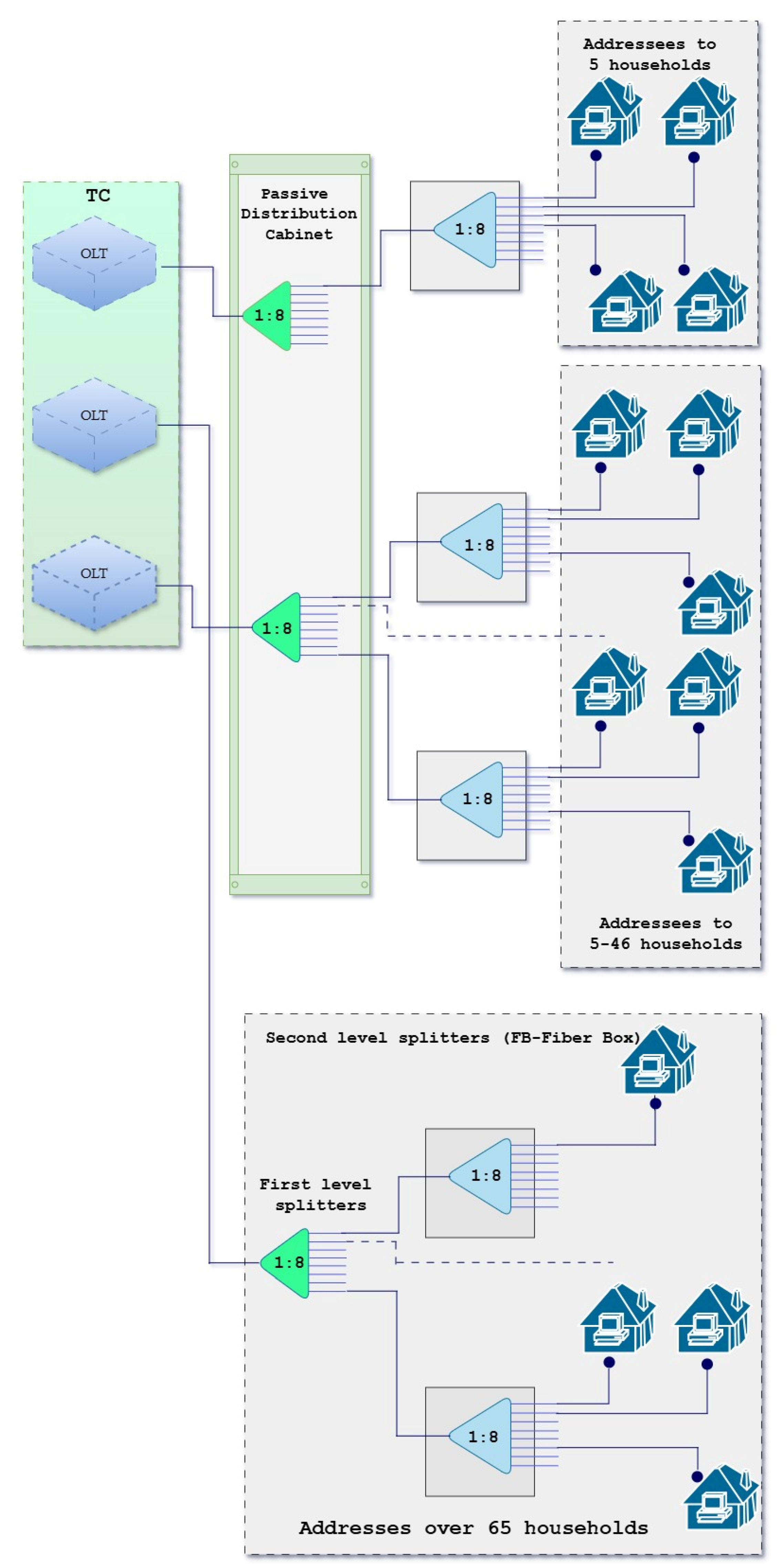
When designing splitters in a PON network, the basic rule for the GPON is that the product of the first-level and second-level splitting coefficients should be equal to 64, with first-level splitters installed in existing street cabinets or in a technological building when the area around it is directly served.
The design of the branching ratio in the splitters is carried out in the direction from the building entrances to the aggregation point in the following sequence (Figure 1):

Figure 1.
Design of the FTTH splitter.
- Based on the number of households, the branching scheme is first determined.
- All second-level splitters with a division ratio of 1:8 are connected to the outputs of first-level 1:8 splitters located in inspection shafts or a technological room.
- The number of first-level splitters determines the number of fibers that will be needed in the connecting cable to the technological room where the OLT is located.
- First-level splitters are placed in an existing street cabinet or in the technological building itself, when it is serviced immediately around it.
- The number of first-level splitters determines the number of OLT SFPs that will be needed in the local central office.
- The number of OLT cards is determined based on the number of OLT SFPs.
- The number of OLT frames and their type is determined based on the final expected number of cards.
There should be no cases where optical power levels that are outside the normal ones for the system are used, while respecting the accepted definitions for branching ratios and distances up to 6 km from the OLT terminal.
For distances greater than 6 km, the branching ratio should be reduced and an OLT SFP class C+ should be used to ensure the required energy balance.
This study was conducted using an Alcatel GPON ISAM 7302 as the OLT for providing broadband services over the GPON infrastructure (Figure 2).
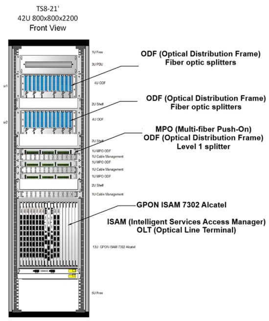
Figure 2.
Alcatel GPON ISAM 7302 provides broadband services via GPON technology, and is part of the ISAM intelligent access platform.
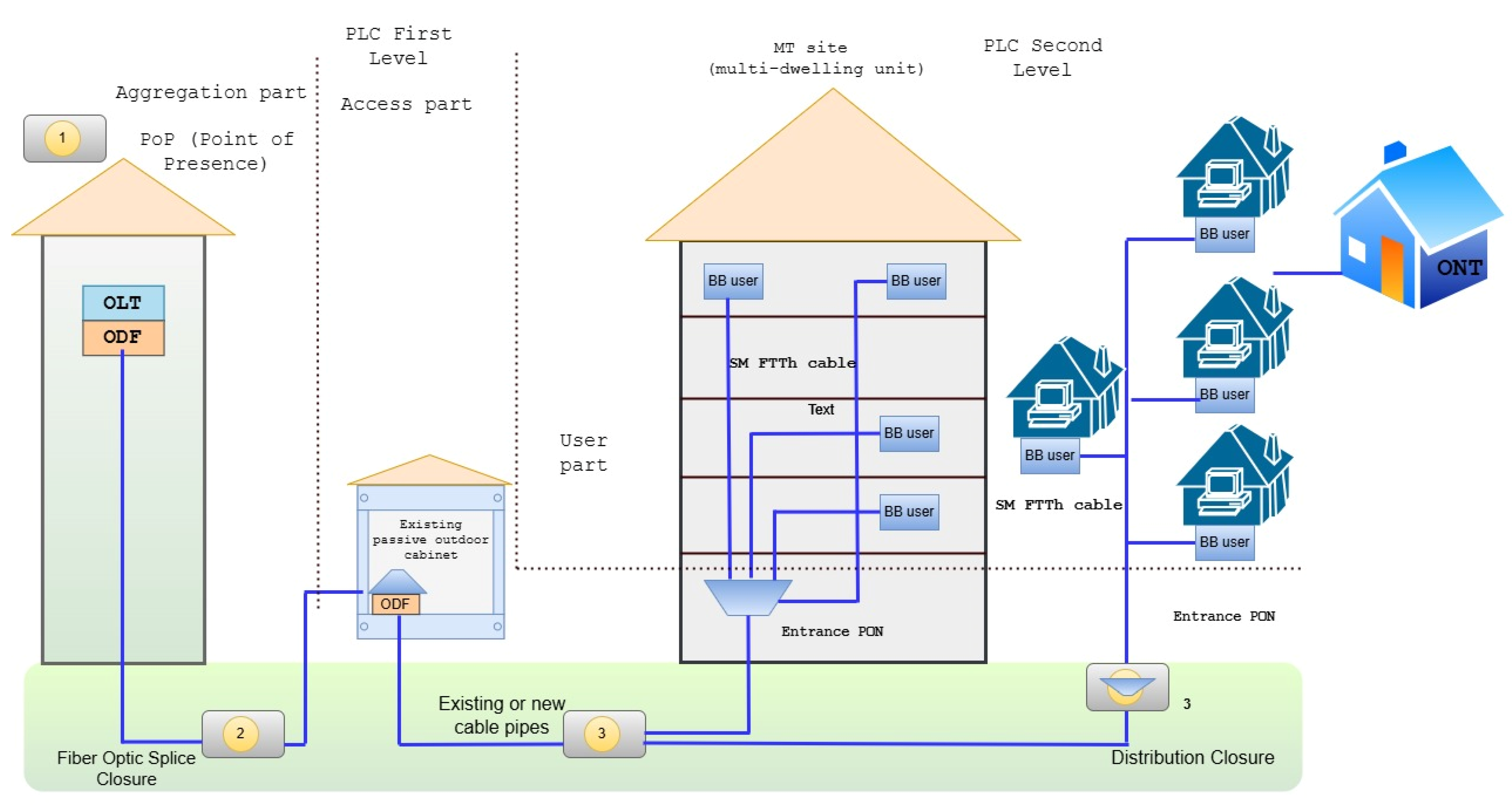
The PON network has a point-to-multipoint architecture, in which passive (unpowered) optical distributors (splitters) are used to serve multiple endpoints over a single optical fiber. Passive equipment includes OLT on the service provider side and ONUs on the end user’s side. The optical fibers branched through splitters between them constitute an ODN. The goal of using these technologies is to provide a full portfolio of fixed services and to enable next-generation access. Passive modules in the PON include WDM coupler, 1×N splitter, optical fiber and cable, connector and ODF/cabinet/rack.
The PON was implemented and a new outdoor PON cabinet was installed on a pre-built foundation, according to the manufacturer’s instructions (Figure 3). The cable was equipped with multi-fiber push-on (MPO) connectors (9xMPO8_APC—72 optical fibers) pulled between the cabinet and the shaft in which the general cable organizer (GCO) socket was to be installed. The pulling direction was from the cabinet to the shaft, because the MPO connectors should not pass through conduits and openings. One separate optical cable was pulled for each PON box.

Figure 3.
Connection of buildings with five or more households with the PON.
The following technical requirements were met during the entire installation process:
- The PON box and the GCO socket can be installed simultaneously.
- The placement of the splitters in the box and the installation of the adapters can be completed in advance.
- Before connecting, the MPO connectors are cleaned with a specialized tool.
- The GCO socket is installed in a closed car to avoid contamination.
- All connectors and splitters are numbered according to the fault discovery protocol.
- It is not allowed to leave a technological reserve of cable larger than that required for hanging the box in the volume of the cabinet. In case of excess cable, it is re-drawn and formed at the GCO.
- All openings in the cabinet to the shaft are sealed to prevent the penetration of humid air from the shaft and its condensation in the cabinet.
- Each PON box is permanently labeled with the designations specified in the FDP on the outer and inner sides of the lid.
- Before closing the boxes, the correct formation and placement of the optical fibers is checked according to the instructions in order to avoid damage when closing it.
- Protective caps are placed on all connectors (adapters) that are not connected.
This method is suitable for housing cooperatives and entrances to blocks of flats in settlements with over 10 thousand inhabitants (mandatory for over 30 thousand inhabitants), and for resort areas where overhead cables are not allowed. It is important to note that special building permits (agreements with building owners) are required when connecting the building to a trench and for internal optical cabling. The connection to the interior of the building is made underground (a hole in the foundation) or at the level of the first floor (with an outlet pipe) depending on the characteristics of the building. The number of fibers in the cable should be four if the households in the entrance are less than or equal to 32. For more than 32 households in the entrance, the building is connected with a fiber optic cable with 12 fibers.
During the installation and configuration of PON, the second-level splitters are located in PON-ES boxes installed in the common areas of the buildings. The connection configuration is as follows:
- Each box serves as a terminal element for FTTH connection cables containing 4/12 OF, which are terminated directly in the PON-ES (passive optical network equipment splice).
- The splitters used, the connection method, and the activated fibers are implemented in accordance with the established standards for passive optical networks (PON) [11].
- A single distribution splice connects up to 4–5 building entrances, and is installed according to the optimized route layout.
- The connection boxes (PON-ES) are installed in the common area of the building, while complying with the requirements for operational maintenance and long-term reliability.
- Fibers are connected to the second level splitter located in the PON-ES module via preinstalled LC/APC connectors (LC—lucent connector, APC—angled physical contact), which ensure quick installation and stable optical connections.
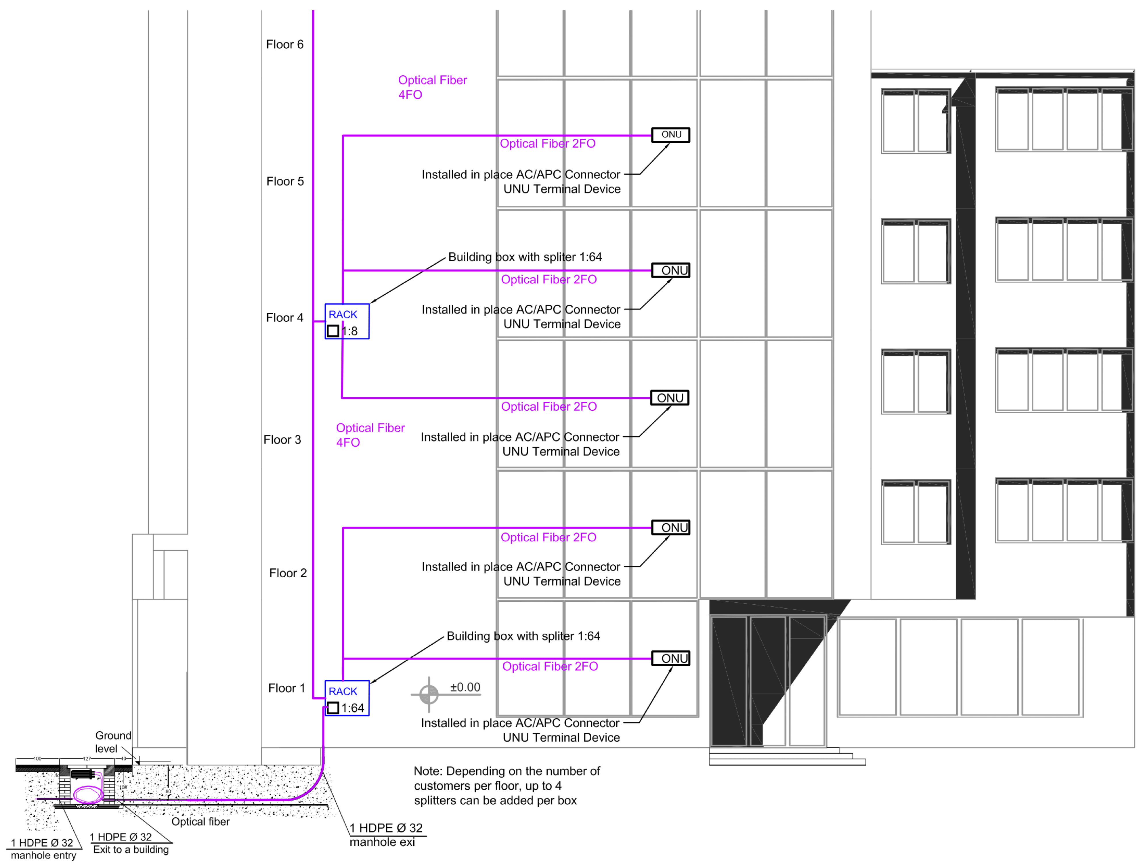
One splitter is provided for every 16 households (single-family homes). Full coverage of the households is achieved with two 1:8 splitters in the connection socket. One OLT port can supply 64 households without a zero-level splitter and can cover 128 households with such a splitter (Figure 4, Table 3).
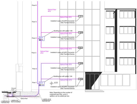
Figure 4.
Installation of the PON boxes in a building with a level 2 splitter and distribution splice closure.
Table 3.
Second level optical splitters used.
As a result of the installation, its flexibility and scalability are demonstrated as well as an effective management of branching logic at the secondary access level.
When there is an existing above-ground infrastructure, such as private houses or hotels, deploying aerial fibers is a cost-effective and efficient way of implementing FTTH. This approach requires special building permits and agreements with building owners due to the routing of the overhead cable. The number of fibers in the distribution cables is between 12 and 72, depending on the number of users.
Optical cables with a capacity of 12–24–72 optical fibers with a non-metallic self-supporting power element, a central element, and several tubes around it are used. The suspension is performed with standard fittings for these purposes.
During the process of implementing a cable connection from the splitter to the end-user premises, several practical and structural requirements need to be observed to ensure reliability and ease of installation in overhead FTTH deployments:
- The drop cable must allow easy separation of the power element and the optical cable element to facilitate handling during installation. An example of an aerial optical cable connection between buildings is presented in Figure 5.
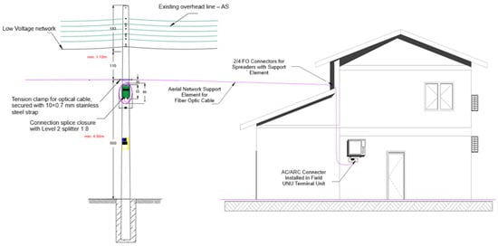 Figure 5. Overhead Optical Cable Connection Between Buildings.
 - The connecting subscriber cable is installed with a suspension element on the pole and on the house, according to the suspension requirements, and the maximum distance between the support points should not exceed 20 m.
- After removing the carrier element from the cable, an SC/APC field-mount connector is installed on site, which provides an optical connection to the ONU subscriber unit;
- Connection cables connect to free optical ports of the PLC splitters located in the connection sleeves or to fibers coming from adjacent sleeves with splitters.
Once the connections to the subscribers have been successfully run, the next step in the PON construction is to install the optical connectors. This process meets the specific requirements for managing, accessing, and maintaining the cable reserve in order to ensure the reliability and maintainability of the network.
When installing optical connectors, the following features are observed:
- Installation of fiber optic connectors is completed on an existing pole with a metal band and plate from the connector kit.
- The plank is placed parallel to the roadway, if possible, on the side of the pedestrian strip 20 cm below the point of suspension of the optical cable.
- There are two reserves of cable for aerial installation, including one to use when the socket can be disassembled from the ladder and the fibers are to be welded in a workspace next to the ladder (400 cm) and one to install inside the socket (150 cm).
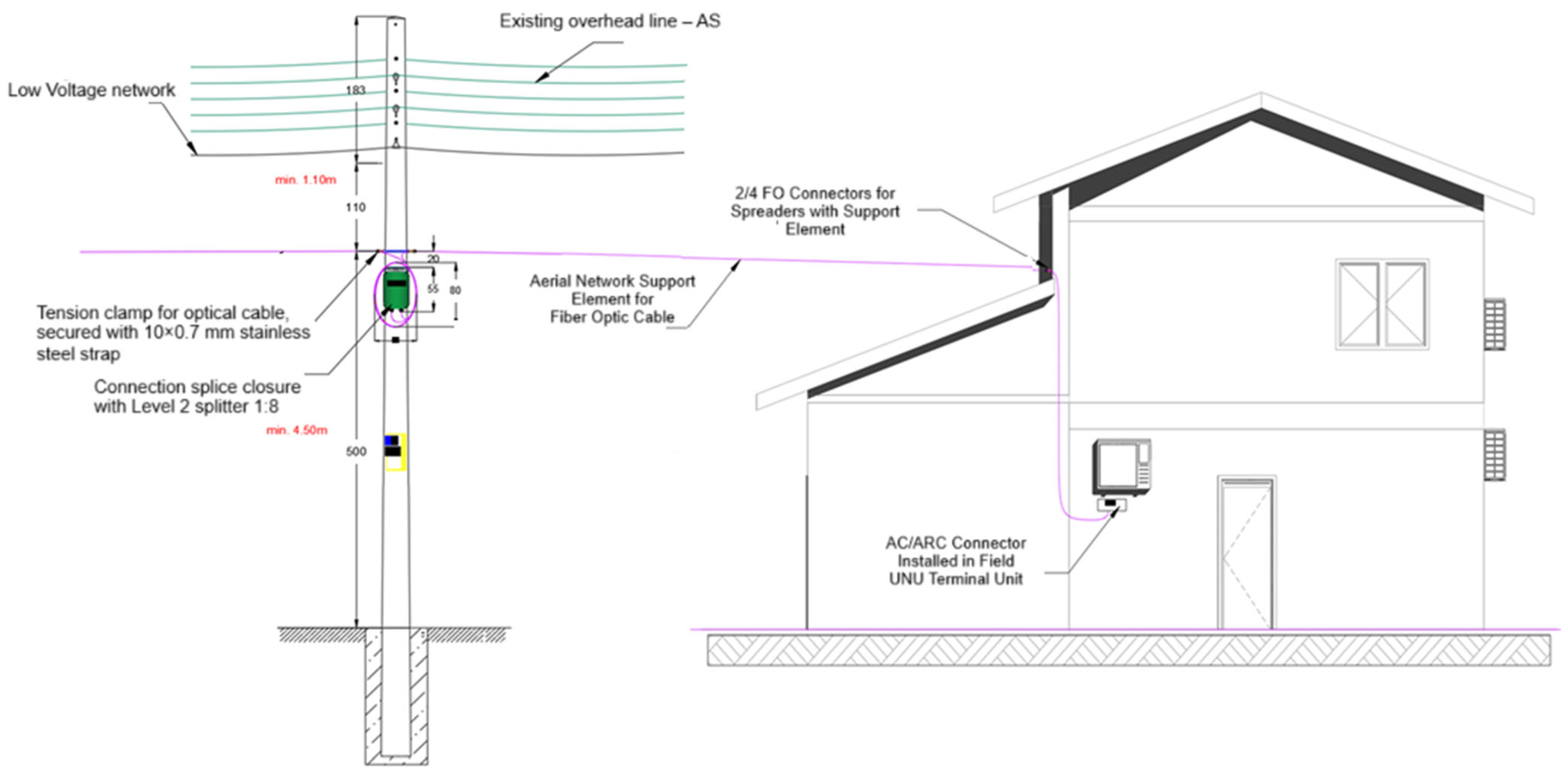
- The configuration and placement of the cable is carried out according to the geometric requirements specified in Figure 6, and it is not allowed to leave a spare cable longer than 5 m on each side.
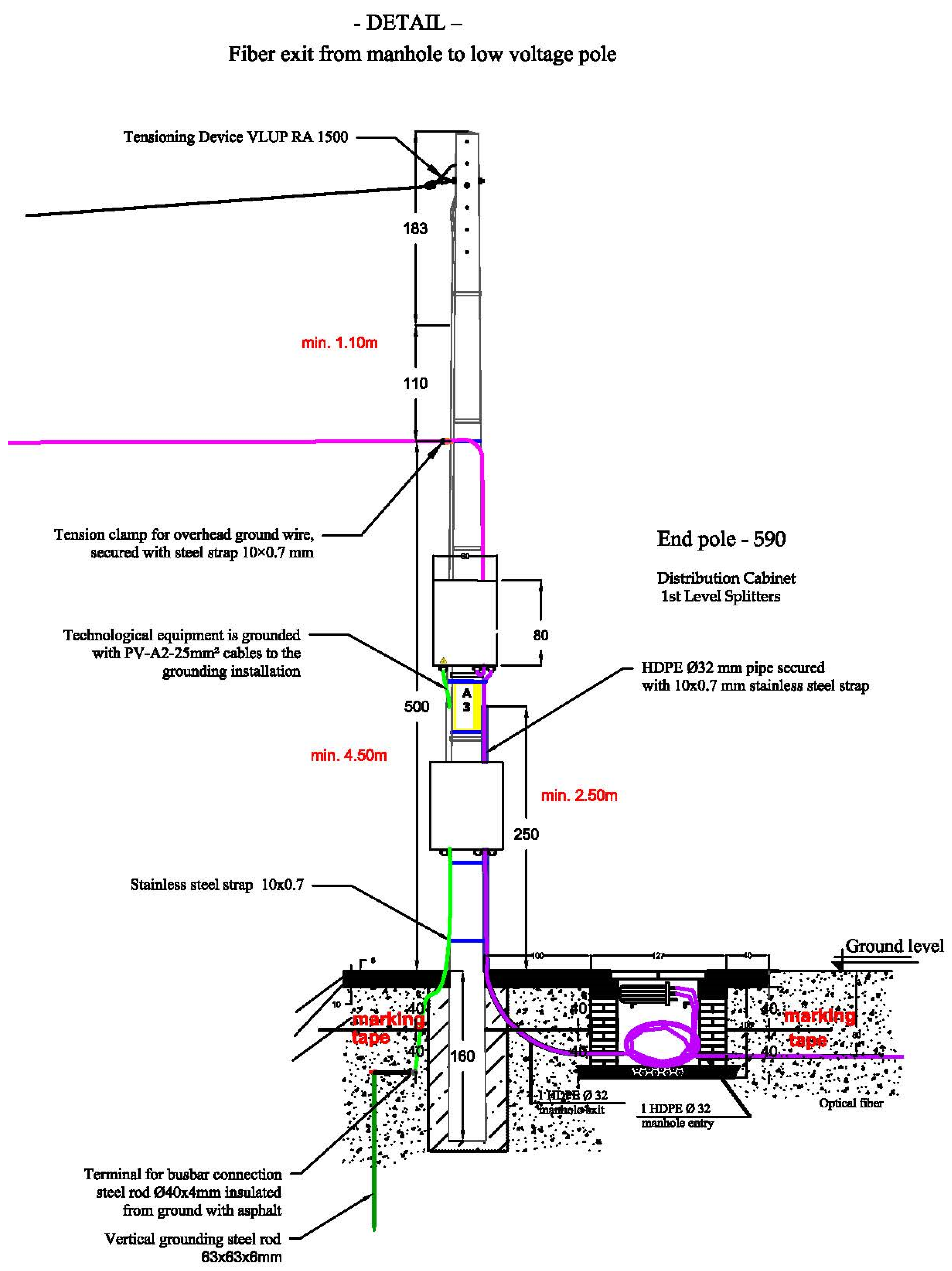
 Figure 6. Detail of fiber exit from manhole to low voltage pole for a PON on a pole.
 - The permissible reserve for future installation of the socket without interruption of the cable must be up to 13 m, measured from the point of suspension of the cable.
A detail of fiber exit from manhole to low voltage pole for a PON (CC590), located in Southwestern region, Blagoevgrad, Bulgaria, can be seen in Figure 6. It illustrates the route of the aerial cable, the splitters in the distribution cabinet, the HDPE pipes, the socket sleeves in shafts, the grounding system, and the cable tensioning assembly. This construction approach is used by various telecommunications service providers in the region. Such aerial PON installations significantly reduce construction costs and are suitable for fiber optic connectivity in areas with low construction.
After the main elements of the PON have been installed, such as the terminal poles, distribution cabinets, and connection sockets, the next important step in the construction of the network is the connection of the individual subscribers by connection cables. This is a process that is associated with precise planning and execution in order to guarantee optical continuity, minimal signal losses, and resistance to external influences [20,21,22].
Optical modules with two fibers are included in the patch cables and, when connected to the carrier element, the optical module is separated by an additional 86 cm, equal to the reserve of the distribution cable plus the reserve necessary for the installation of the SC/APC connector and the formation of the reserve within the socket. The reserve is formed around that of the distribution cable, ensuring a quality connection to the subscriber. The optical connector is installed on the ground surface and then inserted into the socket along with the reserve left. In the next step, the connector installed on the subscriber branch is connected. This stage is important for ensuring a quality and reliable connection.
After connecting the subscriber cables to the splitters in the sockets, it is important to consider the architectural structure of the distribution PON network, which affects the choice of cable infrastructure.
Figure 7 shows how the standard G-PON reach can be extended by introducing a remote extender between the OLT (central office) and the customers (ONTs). Signal distribution is handled by a 1×32 optical splitter beyond the RE, allowing fiber access to remote housing clusters without deploying an OLT in the field.
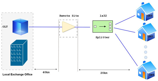
Figure 7.
Reach Extension Architecture for G-PON Mid-Span.
In the network design, the distribution cables in a given area are designed in a mixed topology model and star type, and the rays can be branched. In this structure, the star center for the distribution cables is the aggregation point, from which the radial routes emerge in different directions. The distribution of users is categorized according to the types of buildings that are served. Single-family homes (FH) include houses and small housing cooperatives with up to four households, while multi-tenant buildings (MT) include residential units with five or more households [23,24,25,26,27,28].
In the design of the network and the determination of the number of fibers required, this classification is useful for determining the types of splitters and the capacity of the connecting cabinets. This leads to resource optimization and ensures the resilience of the network.
5. Conclusions
This paper presented the design, implementation, and evaluation of a gigabit-capable passive optical network (GPON) infrastructure for delivering high-speed broadband access in a small-town environment. By adopting a scalable FTTH architecture using passive components, the proposed solution demonstrates an efficient and sustainable alternative to conventional copper-based networks. The detailed design, which includes appropriate branching ratios, OLT-SFP planning, and splitter placement, ensures optimal signal strength, minimal power loss, and high service reliability.
The implementation approach, which involves modular planning, use of standardized optical components, and careful attention to installation practices, proved effective for both underground and aerial deployments. This versatility makes the system suitable for diverse building types and settlement densities, including residential complexes, individual homes, and resort areas with overhead cable restrictions.
The practical results confirm the system’s ability to meet growing digital communication demands, while offering flexibility for future upgrades and minimal maintenance requirements. This study not only validates the technical feasibility of deploying GPON in small towns but highlights its role in accelerating digital inclusion and regional development.
Future work may explore the integration of next-generation PON technologies, such as XG-PON and NG-PON2, to further enhance capacity and to support emerging smart city services.
Author Contributions
Conceptualization, B.Z. and F.S.; methodology, F.S., B.Z., and S.G.; software, B.Z. and S.G.; validation, F.S., B.Z., and S.Z.; formal analysis, S.G. and B.Z.; investigation, B.Z.; resources, B.Z. and F.S.; data curation, S.G. and M.P.; writing—original draft preparation, F.S. and B.Z.; writing—review and editing, S.G., S.Z., M.L., and M.P.; visualization, B.Z.; supervision, B.Z.; project administration, B.Z., F.S., S.G., and M.P.; funding acquisition, S.G., M.L., and M.P. All authors have read and agreed to the published version of the manuscript.
Funding
The authors would like to thank the Research and Development Sector at the Technical University of Sofia for the financial support.
Institutional Review Board Statement
Not applicable.
Informed Consent Statement
Not applicable.
Data Availability Statement
The raw data supporting the conclusions of this article will be made available by the authors upon request.
Acknowledgments
The authors would like to thank the anonymous reviewers, whose comments contributed to the improvement of the quality of the paper.
Conflicts of Interest
The authors declare no conflicts of interest. The funders had no role in the design of this study; in the collection, analyses, or interpretation of data; in the writing of the manuscript; or in the decision to publish the results.
References
- Mendonça, S.; Damásio, B.; Charlita de Freitas, L.; Oliveira, L.; Cichy, M.; Nicita, A. The rise of 5G technologies and systems: A quantitative analysis of knowledge production. Telecommun. Policy 2022, 46, 102327. [Google Scholar] [CrossRef]
- Shafi, M.; Molisch, A.; Smith, P.; Haustein, T.; Zhu, P.; De Silva, P.; Tufvesson, F.; Benjebbour, A.; Wunder, G. 5g: A tutorial overview of standards, trials, challenges, deployment, and practice. IEEE J. Sel. Areas Commun. 2017, 35, 1201–1221. [Google Scholar] [CrossRef]
- Favuzza, S.; Zizzo, G.; Vasile, A.; Astolfi, D.; Pasetti, M. Comparative Analysis of Charging Station Technologies for Light Electric Vehicles for the Exploitation in Small Islands. Energies 2025, 18, 1477. [Google Scholar] [CrossRef]
- Ramaswami, R.; Sivarajan, K.; Sasaki, G. Optical Networks: A Practical Perspective; Morgan Kaufmann: Burlington, MA, USA, 2009. [Google Scholar]
- Nzekwu, N.; Fernandes, M.; Fernandes, G.; Monteiro, P.; Guiomar, F. A comprehensive review of uav-assisted fso relay systems. Photonics 2024, 11, 274. [Google Scholar] [CrossRef]
- Muciaccia, T.; Gargano, F.; Passaro, V. Passive optical access networks: State of the art and future evolution. Photonics 2014, 1, 323–346. [Google Scholar] [CrossRef]
- Lin, C. (Ed.) Broadband Optical Access Networks and Fiber-to-the-Home: Systems Technologies and Deployment Strategies; John Wiley & Sons: Hoboken, NJ, USA, 2006. [Google Scholar]
- G.984.1. Available online: https://www.sternkom.de/global/pdf/sternkom/G_984_1_General_Characteristics_PONfeederprotectionredundancy.pdf (accessed on 1 July 2025).
- Lallukka, S.; Raatikainen, P. Passive Optical Networks: Transport Concepts; VTT Technical Research Centre of Finland: Espoo, Finland, 2006; p. 597. [Google Scholar]
- Effenberger, F.; Ichibangase, H.; Yamashita, H. Advances in broadband passive optical networking technologies. IEEE Commun. Mag. 2001, 39, 118–124. [Google Scholar] [CrossRef]
- Abdellaoui, Z.; Dieudonne, Y.; Aleya, A. Design, implementation and evaluation of a Fiber to The Home (FTTH) access network based on a Giga Passive Optical Network GPON. Array 2021, 10, 100058. [Google Scholar] [CrossRef]
- Ethernet Alliance. Available online: https://ethernetalliance.org/ (accessed on 1 July 2025).
- FSAN. Available online: https://www.fsan.org/ (accessed on 1 July 2025).
- ITU. Available online: https://www.itu.int/en/ITU-T/Pages/default.aspx (accessed on 1 July 2025).
- Horvath, T.; Munster, P.; Oujezsky, V.; Bao, N.-H. Passive Optical Networks Progress: A Tutorial. Electronics 2020, 9, 1081. [Google Scholar] [CrossRef]
- Terayon. DOCSIS 2.0 and Advanced S_CDMA: Maximizing the Data Return Path, Terayon White Paper. 2001. Available online: https://www.terayon.com (accessed on 1 July 2025).
- Cisco. Available online: https://www.cisco.com/c/en/us/support/docs/switches/catalyst-pon-series/216230-understand-gpon-technology.html (accessed on 1 July 2025).
- Hantoro, G.D.; Priambodo, P.S.; Wibisono, G. Analysis of GPON capacity by hybrid splitting-ratio base on customer segmentation for Indonesian market during the COVID-19 pandemic. EUREKA Phys. Eng. 2022, 4, 152–169. [Google Scholar] [CrossRef]
- Vandaele, P.; Peter Vandaele POL Consulting. POL Basics—GPON. 2020. Available online: https://poldigitaltransformation.blogspot.com/2020/04/pol-basics-gpon.html (accessed on 1 July 2025).
- Sapundzhi, F. A survey of KNX implementation in building automation. TEM J. 2020, 9, 144–148. [Google Scholar] [CrossRef]
- Sapundzhi, F.; Popstoilov, M. Maximum-flow problem in networking. Bulg. Chem. Commun. 2020, 52, 192–196. [Google Scholar]
- Sapundzhi, F.; Mladenov, M. An Android-based mobile application giving information for weather in real-time. Bulg. Chem. Commun. 2022, 54, 89–91. [Google Scholar]
- Sapundzhi, F.; Popstoilov, M. Optimization algorithms for finding the shortest paths. Bulg. Chem. Commun. 2018, 50 (Special Issue B), 115–120. [Google Scholar]
- Nedyalkov, I. Application of GNS3 to study the security of data exchange between power electronic devices and control center. Computers 2023, 12, 101. [Google Scholar] [CrossRef]
- Nedyalkov, I. Benefits of Using Network Modeling Platforms When Studying IP Networks and Traffic Characterization. Computers 2023, 12, 41. [Google Scholar] [CrossRef]
- Sapundzhi, F. Home automation based on Z-wave technology. Bulg. Chem. Commun. 2022, 54, 92. [Google Scholar]
- Sapundzhi, F.; Yordanov, K. Network monitoring of the MHT company using the DUDe. Bulg. Chem. Commun. 2020, 52, 211–219. [Google Scholar] [CrossRef]
- Nedyalkov, I. Comparison in the applicability of MPLS when using different dynamic routing protocols. Int. J. Electr. Electron. Eng. Telecommun. 2022, 11, 42–53. [Google Scholar] [CrossRef]


Disclaimer/Publisher’s Note: The statements, opinions and data contained in all publications are solely those of the individual author(s) and contributor(s) and not of MDPI and/or the editor(s). MDPI and/or the editor(s) disclaim responsibility for any injury to people or property resulting from any ideas, methods, instructions or products referred to in the content. |
© 2025 by the authors. Licensee MDPI, Basel, Switzerland. This article is an open access article distributed under the terms and conditions of the Creative Commons Attribution (CC BY) license (https://creativecommons.org/licenses/by/4.0/).