1. Introduction
The increasing number of EVs requires corresponding adaptations to the network infrastructure and its energy parameters. The operation of EVs leads to a significant reduction in environmental pollution and a reduction in the financial resources allocated to oil and gasoline. However, increasing electricity consumption is demanding changes in grid infrastructure and transformers to enable fast charging of electric vehicles [
1]. The lack of charging infrastructure creates significant difficulties in operating EV fleets.
Currently, the problems faced by EVs relate to long charging periods, the limited power of existing batteries, and short driving ranges [
2]. The increasing use of EVs requires the implementation of appropriate energy management for charging stations to timely service charging requests [
3]. The potential benefits of EV operations are seen in energy connections and performing operations such as vehicle-to-grid (V2G), vehicle-to-vehicle (V2V), vehicle-to-home (V2H), and vehicle-to-building (V2B) [
4]. These applications extend the EV’s transportation functions to the domain of electrical storage, energy support, and reducing grid power fluctuations. In particular, these applications can help efficiently charge and discharge EV batteries and extend their energy life.
The batteries that power EVs are moving in line with technological evolution, advancing from Lead-Acid to Nickel-based batteries, and currently to Lithium-based solutions [
5]. The energy capacity, measured in kWh (Kilowatt-hour), is the overall integral characteristic of the battery. This affects the travel range of EVs and how far they can be driven without recharging. Charging characteristics classify EVs into three main categories [
6]. Level 1 charging is designed for EVs with a 120 V (volt) supply, while Level 2 provides a 240 V connection. Both levels use single-phase electrical charging, and their charging power ranges from 2 to 22 kW.
Level 3 is a three-phase AC power solution that provides DC power for fast charging of EVs and charging power of 2–240 kW. However, the growth in the use of EVs has led to a significant increase in the electrical load on the current energy infrastructure.
Charging control can be implemented in a centralized and decentralized manner. For the centralized concept, all data are collected in a centralized framework, where data processing is provided and optimal charging solutions are evaluated [
7]. In decentralized control, each electric vehicle user, rather than other systems or people, makes the decisions. In this case, the user personally chooses charging options and may be supported informatively, but the decision-making is individual. Widely used charging systems are connected to the grid, which can provide power within the limitations of the respective regional transformer. Despite this easy-to-use solution, the charging process will be affected by general grid characteristics and disturbances such as higher peak load demand, resulting in lower power quality. Charging of EVs should avoid grid congestion. Modeling and optimization problems have been defined and developed for various problems [
8]. The optimization of the charging schedule by means of cost minimization is formalized in [
9]. The optimal allocation of charging power among vehicles in a parking lot is presented in [
10]. In [
11], charging and discharging prediction and aging analysis of energy storage are presented. Minimizing energy flows is a problem in [
12].
This study aims to minimize the charging time of a group of EVs by redistributing energy power to a set of charging stations. These stations can be located in an urban area, but are powered by the same grid resource, which has limitations in its electricity capacity. Optimal energy capacity allocation aims to minimize the total service time of a set of EVs that simultaneously charge their batteries with different storage capacity requirements.
2. Materials and Methods
Currently, the battery is considered a technological tool for storing and using electrical energy. Therefore, it has the characteristic of two-way energy flow. The time for charging and recharging a battery can be derived from the law of conservation of energy, which can be formally expressed as the energy entering the battery, E
ch, from a charging station charges the battery with energy E
bat (
Figure 1), and the following equality is valid:
This is an ideal case, which does not take into account the losses, ΔE, that always exist in real systems. The values of Ech and Ebat are measured in watts [W], respectively, for the power of the EVs in [kW, 1 kW = 1000 W].
Following (1), both sides are multiplied by the time
T, which is currently defined by hours [
h], as follows:
Multiplying the right side of (2) gives the battery capacity C
bat in [kWh], as follows:
The relation (3) can be modified with a parameter 0 ≤ α ≤ 1, which gives the fraction of the total battery capacity α
Cbat that needs to be charged. Following (3), it holds for the recharge time, which can be estimated as the relation:
Charging time increases as the capacity of the EV battery increases and decreases when a powerful Ech charging station is used.
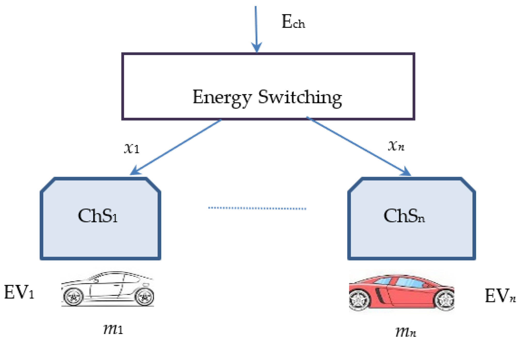
This research is aimed at solving the problem of distributing and redistributing charging power
Ech between centralized or distributed charging stations that are powered by a common energy input, E
ch (
Figure 2).
The switching unit performs the redistribution of energy Ech between n charging stations ChSi i = 1,…,n. Each station must charge EVs with individual capacity , i = 1,…,n.
Since a common energy flow
Ech is used, the redistribution of power flows to the charging stations is denoted by x
i, i = 1,…,n. All energy flows must satisfy the energy conservation requirement:
Minimizing the total loading time is formalized with the objective function as follows:
where it is assumed that the capacity αC
bat,
i of the vehicle batteries is known.
The optimization problem is formulated as a nonlinear problem
The interpretation of the coefficient is the part of the battery capacity that is empty and needs to be charged. The upper and lower limits are established for practical and technological reasons for each charging station. Problem (6) is a nonlinear optimization problem and, despite its simple form, the solution may raise computational time issues due to the nonlinear form of the objective function. Problem (6) requires an estimate of all energy needs , i = 1,…,n, or the battery capacity.
Problem (6) can be reformulated by taking into account the common values of the powers
for the different capacities
of the batteries. This solution will give the total time and the individual times if the charging stations deliver the same power
x =
const to all chargers, despite the different capacities of the EV batteries.
The solution to (7) gives the sequence and schedule that will result from the charging process. It is easy to see that the lowest capacity of the battery will be the first charge. However, in the case of renewing the queue of waiting EVs, the current battery capacity state must be taken into account for the new solution to the problem (7).
3. Numerical Simulations and Results
We assume a charging infrastructure as presented in
Figure 2, with
n = 4. The device at the top level represents a source of electrical energy, with power
Ech that must be redistributed between four chargers. An additional interpretation could be the redistribution of electrical power between four regions, made by the corresponding transformer. For the numerical simulations, we assume that four EVs are connected to the chargers and the charging process starts simultaneously for all EVs. The electrical power of the source is assumed
which is the currently used case for level 2 charging stations. This power must be redistributed between the four charging units, each of which will receive
. The sum of the distributed power must be less than
. To have different values for the charging units
, four different values of the battery capacity of EVs are taken, denoted by
. We use the most common capacities of level 2 batteries, as given in
Table 1.
The total power
, required for the simultaneous charging of all EVs is chosen to be higher than the available power
Ech of the charging infrastructure:
This case is considered because if , there is no need for power redistribution, and accordingly, each EV can charge with its required capacity. The redistribution of power is evaluated by solving problem (6). We will solve three cases by changing the order of charging and evaluating the results according to the service time of the group of vehicles connected to the chargers.
3.1. Case 1: Simultaneous Charging of All Vehicles
Problem (6) with the parameters from
Table 1 takes the analytical form:
To simplify problem (8), we assume that the coefficients
, since we will explicitly estimate the battery capacity during the calculations. The solution to problem (8) gives:
This distributed electrical power will charge the batteries for periods estimated according to ratio (4) or
which gives
or
The minimum time from
t is as follows:
For the time
the batteries of all EVs are charged, and the residual capacity that requires additional charging of the vehicle is as follows:
Since
this indicates that the EV
1 is charged. However, during the time
all batteries are charged and the remaining capacities are calculated according to the ratio (10) or
To simplify the following notation, we make a running substitution
=
,
i = 2,…,4. For Case 1, it is assumed that the remaining capacity of the batteries continues to be charged with solution
x. The next time to full charge is to EV
2 because
t2 = 0.91 is the closest to
The difference between the charging time of EV
2 and EV
1 is as follows:
During time
the batteries of cars EV
2, EV
3, and EV
4 will be additionally charged and their remaining capacity is as follows:
These results confirm that EV
2 has charged its battery. The remaining cars will continue to charge during the time difference
We make the current substitution again
=
,
i = 3,…,4. During this period
the batteries of EV
3 and EV
4 change the level of the requested capacity to the values
EV
3 has finished charging. The last EV
4 vehicle continues to charge for the time being
and checks whether the remaining charge capacity indicates that the battery is fully charged or
The service time of all vehicles
T1 for Case 1 is the sum of all times
t or
The mean time for servicing a car is as follows:
The battery charging process is illustrated in
Figure 3. The decreasing trends illustrate how the required capacity to charge the batteries decreases over time. EV
1 has the lowest capacity and goes to zero in the shortest duration. EV
4 has the highest capacity, and its duration is the longest. The charging behavior of other cars lies between these extreme cases.
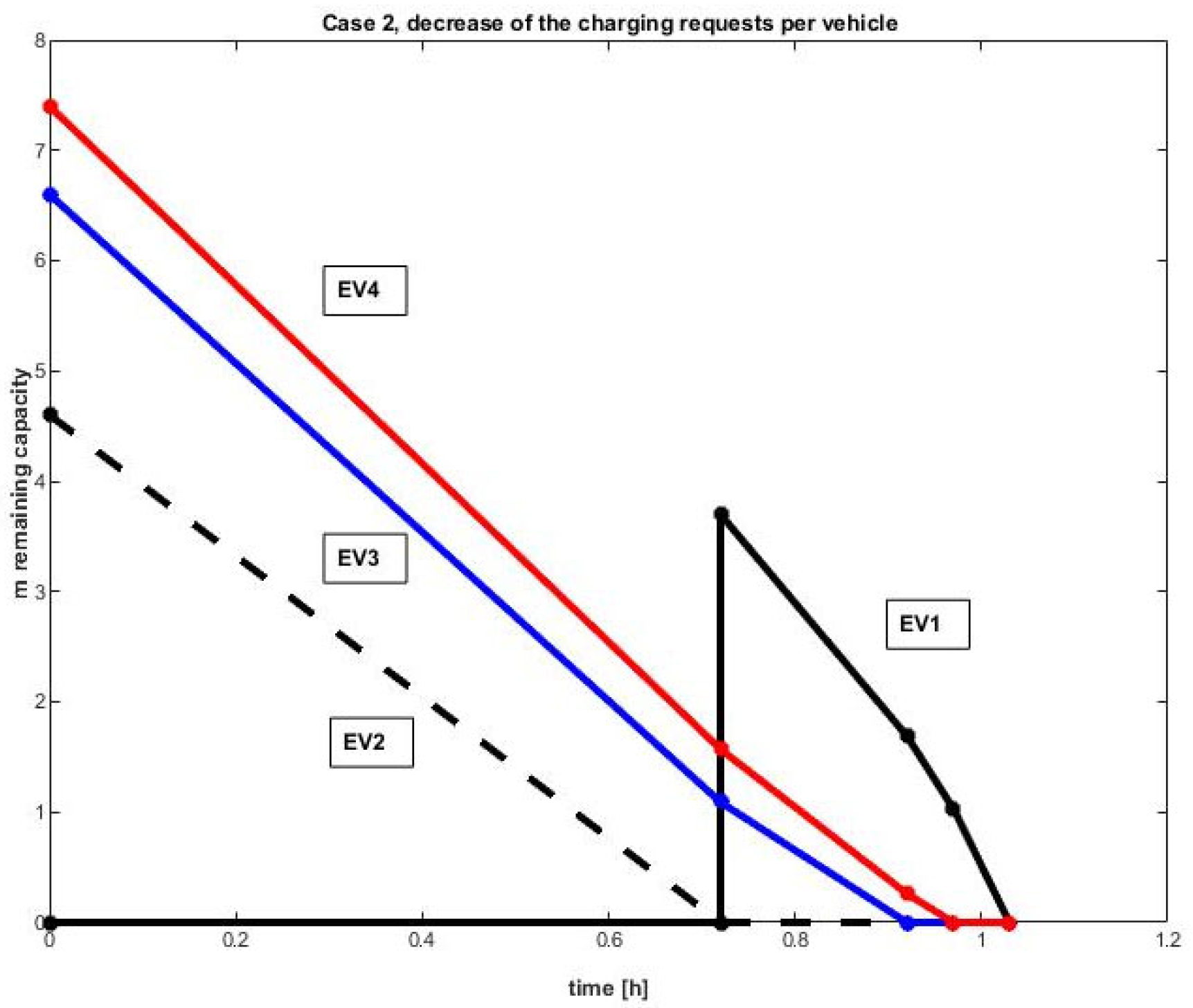
3.2. Case 2: The Highest Capacity Is First and the Smallest Is Waiting
The sequence of vehicles that can begin charging can affect service time. The evaluation of this case is performed assuming that the battery with the highest capacity is charged from the beginning. The reason for this choice comes from the requirement for the highest capacity compared to the permissible load of the charging station. In our case, the requested power is 22.3 > 22 [kW]. One solution is to have the vehicle wait for its turn when the requested power drops to the possible limits. That is why for Case 2 we chose EV
1, which needs the smallest capacity
m1 = 3.7 [kWh] for waiting for a free position at the charging station. The distribution of charging power between EV
2, EV
3, and EV
4 is estimated by (6) with the battery capacity parameter
mT = [0; 4.6; 6.6; 7.4]. Analytically, the problem is formulated as
First problem:
The solution to (10) gives
The time for the charging of these batteries is evaluated according to (9) or
The minimum time to complete a charge is
tmin = 0.72, which is for EV
2. The remaining battery capacity after time
tmin is estimated according to (10) or
This result shows that EV
2 has charged its battery. The charging power is released, and the first EV
1 can start charging. The new optimization problem accepts these new parameters by substituting
. The analytical form of the new problem is given below as the
Second problem.
The next solution to this modified problem gives
These solutions define the final charge time as
The minimum charging time is t
min = 0.20, which belongs to EV
3. The remaining battery capacity after the time t
min = 0.2 is again calculated from (10) or
Therefore, the battery of EV
3 is charged. The charging power distribution is made for EV
1 and EV
4. The corresponding optimization problem (6) is given below as the
Third Problem.
These solutions determine the time it takes to fully charge an electric vehicle:
The minimum time is for EV
4 with
tmin = 0.04. After charging for time
tmin = 0.04, the remaining battery capacity is
Therefore, the EV
4 battery is fully charged. The final charge of the EV
1 battery will be completed in time.
For this last case, the full power of 22 [KW] is allocated to EV
1 since no other cars are waiting to charge, and problem (6) becomes trivial with a trivial simple solution. The service time of each car is equal to the waiting and charging time. The results of these times are illustrated in
Table 2.The service time of all vehicles T2 for Case 2 is the sum of all times
t or
The average service time for a vehicle is
The battery charging process for Case 2 is illustrated in
Figure 4.
EV
1 waits to be turned on after EV
2’s charging time. Although EV
4 has a high charging requirement, it has finished charging before EV
1. The important result here is that by changing the loading order, the service time for Case II is reduced compared to the regular loading of Case I:
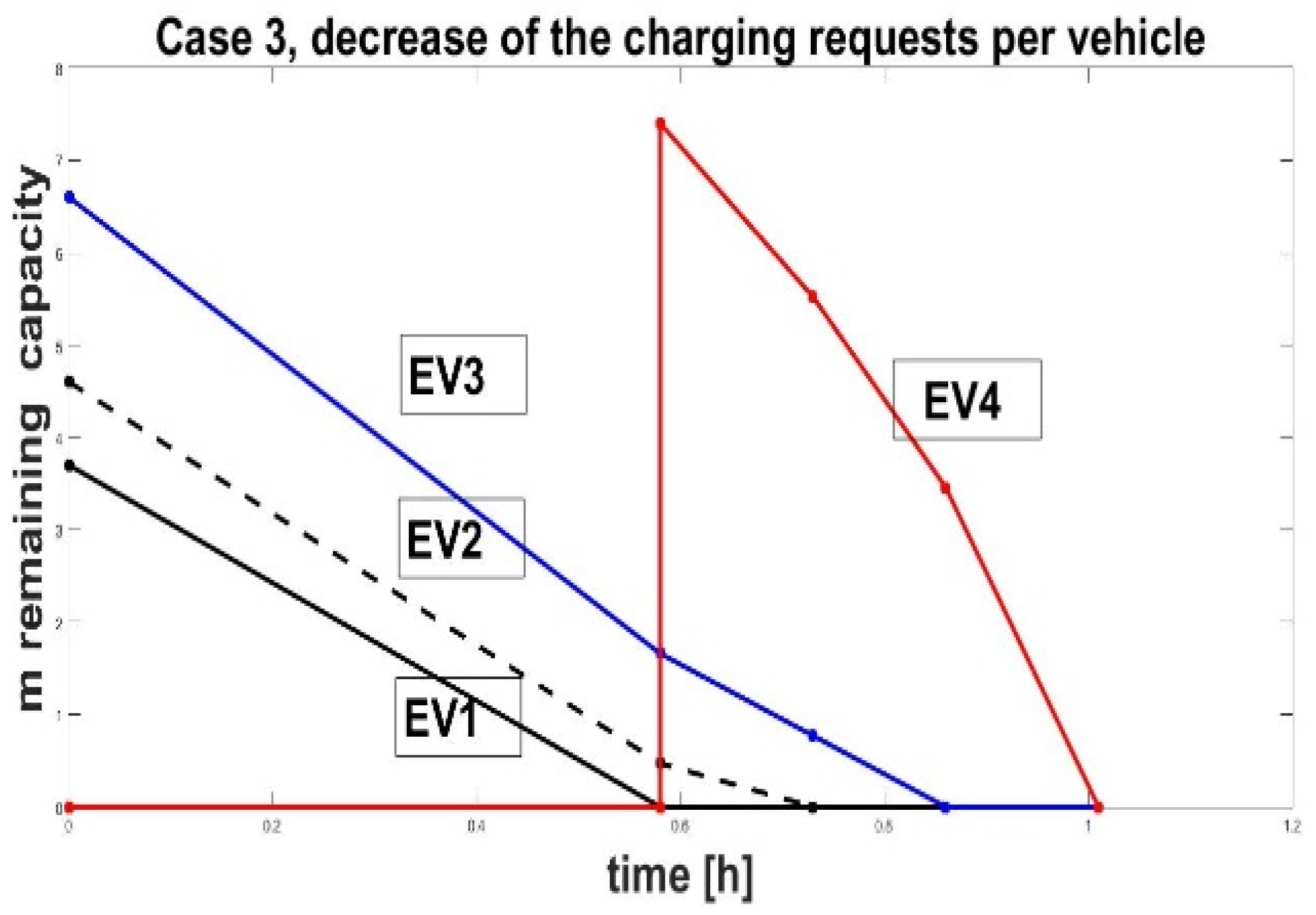
3.3. Case 3: The Smallest Capacity Is the First One, and the Highest Is the Waiting One
Since the total power required for charging is higher than the charging station capacity, E
ch _ total = 22.3 > 22 =
, we will apply a scheduling strategy that differs from Case 2. For this case, the charging schedule of the vehicle with the highest battery capacity is awaited. The optimization problem (6) is defined with the parameters of EV
1, EV
2, and EV
3, according to (8):
The distributed energy solution is as follows:
where
x4 = 0 because EV
4 is waiting and not charging. The charging time for this battery pack is estimated at
The minimum charging time is
tmin = 0.58 [h], which belongs to EV
1. The residual capacities of the batteries after the time
tmin, calculated by (10), are as follows:
Therefore, the battery EV
1 is charged, and additional power capacity is released, and EV
4 can start charging. The new optimization problem (6) is given below as the
Second problem.This modified problem (6) gives the solution
where
x1 = 0 since EV
1 is charged. These solutions define the final charging time as
The minimum time is for EV
2 with t
min = 0.15. After charging for time t
min = 0.15, the remaining capacities of the batteries are
Therefore, EV
2 has also charged its battery. The new optimization problem (6) is given below as the
Third problem.
The solution to this modified problem gives
where
x1 =
x2 = 0, since EV
1 and EV
2 have been charged. These solutions determine the final charging time as
The minimum time is for EV
3 with
tmin = 0.13. After charging for time
tmin = 0.13, the remaining capacities of the batteries are
This indicates that the EV
3 has charged its battery. The remaining capacity is for the EV
4.
For this last case, the full power of 22 [kW] is allocated to EV4 since there are no other cars waiting to charge. Problem (6) is trivial with an easy solution.
The estimates of operating time for all vehicles and the average are given in
Table 3.
The service time of all vehicles T3 for Case 3 is the sum of all times
t or
The average service time for a vehicle is as follows:
The battery charging time schedule for
Case 3 is illustrated in
Figure 5.
The highest capacity EV
4 battery charges last the longest. However, the comparison between service times for Cases 1, 2, and 3 is valid.
This result proves the conclusion that if the charging station power is less than that required by the batteries, scheduling with the least charged EV battery first is the most advantageous solution for charging time for all vehicles.


