Proceeding Paper

Helicopter Rotor Aerodynamic Characteristics in Ground Effect: Numerical Study †

Department of Aeronautics, Technical University of Sofia, 1000 Sofia, Bulgaria
Presented at the 14th International Scientific Conference TechSys 2025—Engineering, Technology and Systems, Plovdiv, Bulgaria, 15–17 May 2025.
Eng. Proc. 2025, 100(1), 13; https://doi.org/10.3390/engproc2025100013
Published: 4 July 2025

Abstract

This article represents a full estimation of helicopter rotor aerodynamic characteristics in ground effect conditions through the application of a coupled empirical blade element–momentum theory algorithm. The main focus of this research includes the evaluation of the required weighted power coefficients C P σ for a hovering state in close proximity to obstacles and their relation to the weighted thrust force coefficients’ values C T σ , varying the relative distance from the helicopter rotational plane to the ground surface H R and the rotor’s collective pitch angle (θ). The represented numerical and experimental results show that an increase in the collective pitch angles (θ) leads to a rise in the generated weighted thrust force coefficients C T σ and in the weighted power coefficients C P σ for every individual fixed normalized distance from the ground surface H R . Moreover, a decline in the relative distance from the ground H R requires less power to keep the rotation going in hover. The dependencies indicate that the ground effect zone covers a distance of up to 2R from the rotational plane to the ground surface.

1. Introduction

When operating in a hovering regime in ground effect conditions, helicopter rotors experience a decrease in the required power (P) for a given thrust (T), which leads to a requirement for the provision of adequate control actions for fulfilling the hover conditions and for delivering a smooth and stable taking off and landing. The ground effect zone quantification is essential in ensuring the rotorcraft dynamics in the vicinity of obstacles. To correctly quantify the ground effect zone, the coefficients of power C P must be estimated, varying several operational parameters, such as the relative distance from the ground surface H R and the blade collective pitch angle (θ). The evaluation of the power coefficients C P in low-Reynolds-number conditions requires a detailed approach to correct the corresponding aerodynamic characteristics with respect to the required power (P). Several attempts were made at the dawn of helicopter aviation to achieve rotor characteristic description in the ground effect zone. Knight and Hefner presented a mathematical analysis of rotor general characteristics in ground effect, validated with experimental results from three lifting airscrew models [1]. The researchers successfully derived the thrust and torque magnitudes, (T) and (Q), respectively, in the ground effect zone, while experiments indicated a rise in thrust values when the rotor operated close to the ground surface. The torque remained relatively constant, except for at very small distances from the ground [1]. Moreover, Fradenburgh experimentally demonstrated that a helicopter requires only minor, if any, increases in power when it operates in a transitional mode from hover to horizontal flight, and losses only occur when it operates over sloped surfaces [2]. The researcher concluded that only a surface that is positioned in the flow field can affect rotor aerodynamic characteristics due to the change in pressure gradients [2]. A decrease in ground effect intensity with an increase in height (H) was quantified by Heyson [3]. It was found that the decrease in the ground effect intensity was higher in forward flight in comparison to the hovering rotor in ground effect. A major decrease in ground effect intensity is observed when the helicopter rotor operates at speeds less than 1.5 times the mean hovering-induced velocity [3]. Rotaru and Todorov suggested an increase in helicopter efficiency due to the interference between the rotor and the ground, which leads to a decrease in the inflow ratio in the rotational plane and a decrease in the angle of attack (α) [4]. The ground effect phenomenon causes a change in the wake-induced velocity due to the interaction with the ground plane [5]. A typical representation of this phenomenon is made in terms of figures of merit as a function of the relative distance from the ground surface [5]. Johnson described the ground effect with a function, ( f g ), which directly relates the power into and out of the ground effect zone, (P) and ( P ) , respectively. The ground influence is stronger on a tiltrotor, compared to an isolated rotor, due to the wing and fuselage download reduction [5]. The influence between the helicopter rotor and an inclined ship deck was represented by Xin et al. [6]. Researchers derived the ground influence coefficient matrix {G}, which relates the ground interference velocity, the rotor pressure coefficients as a function of the rotor height (H), and the deck inclination angle [6]. A helicopter rotor hovering at differing positions in relation to the ground surface was examined experimentally by Gibertini et al. Particle Image Velocimetry was conducted to assess pressure distribution derivation [7]. Multicopter flights in the vicinity of obstacles cause a variety of flight control complications, mainly due to the ground effect phenomenon. The ground effect phenomenon causes a change in the aerodynamic parameters when the multirotor flies in the vicinity of obstacles and specifically leads to a rise in the generated thrust (T) and a decline in the required power (P). Georgiev et al. successfully quantified the major aerodynamic dependencies of a multicopter, operating in ground effect conditions [8]. The quantification includes dependencies between the generated thrust (T) and the required power (P), varying the rotational frequency (n), the operational distance from the ground surface (h), and the rotational plane inclination angle (δ). An increase in the inclination angle (δ) leads to a decline in ground effect intensity. Moreover, the dimensionless analysis estimates the ground effect zone length, which covers the distance from the rotational plane to the ground surface equal to one radius [8]. An experimental quantification of the static characteristics of a helicopter rotor operating in ground effect conditions was presented by Georgiev et al. Dependences between the generated thrust (T) and the required torque (Q), varying the rotational frequency (n) and the operational distance from the ground surface at a fixed collective pitch angle (θ), were drawn [9]. The study showed that the thrust (T) increases and the torque (Q) declines once the rotor operates close to the ground surface. As a result, dimensionless analysis showed that the thrust (T) significantly increases when the rotor operates at distances from the rotational plane to the ground surface lower than 0.5D [9]. The ground effect characterization of a human-powered helicopter rotor was performed by Misiorowski et al. The study successfully derived an empirical model, which relates the parameters in ground effect conditions [10]. An application of a CFD code for rotorcraft studies was represented by Young [11]. Helicopter wakes’ interactions with buildings were examined by conducting wind tunnel measurements, which were used as a tool for determining CFD validity. As a result, the dependencies between the relative distances from the helicopter rotational plane to the ground surface H R and the relative thrust force coefficients C T C T O G E for different advance ratios (μ) were derived [11]. The highest accuracy level was achieved for the static regimes, and it decreased for high advance ratios (μ) [11]. Moreover, a characterization of free-flying helicopters near the ground was conducted by Bauknecht et al. by combining two experimental techniques—Particle Image Velocimetry and Schlieren—for the purpose of studying the helicopter wake’s interactions with the ground surface and the brownout phenomenon, enabling a more complex investigation [12]. Additionally, an aerodynamic study of a coaxial rotor, operating in a descending regime and in ground effect conditions, was conducted by Kinzel et al. [13]. A reduction in thrust loss, associated with the vortex ring state, was observed in the coaxial scheme [13]. The tip vortex geometry of a hovering helicopter rotor in ground effect was photographed with a shadowgraph by Light [14]. The contraction rates of the helicopter rotor tip vortices in ground effect conditions were investigated. Further, a free wake analysis was conducted, and the numerical results showed reasonable agreement with the experimental results [14]. Changes in the helicopter aerodynamic quantities due to wake interactions with the ground surface were experimentally studied by Hanker and Smith [15]. Their study illustrated the changes in the rotorcraft forces and moments due to the variation in the rotor thrust and wind magnitude and direction [15]. A numerical approach was followed by Silva et al. through the application of a finite volume method [16]. Predictions were derived for several collective pitch angles and two distances from the rotational plane to the ground surface for a tip Mach number of 0.585. In detail, pressure distribution, thrust, and torque magnitudes were estimated for the helicopter both in and out of ground effect conditions and consequently validated with experimental data [16]. A numerical study of a 3D hovering helicopter rotor blade operating in a transonic regime in ground effect conditions was presented by Gao and Agarwal [17]. The blade pressure distribution, lift, and thrust performance were calculated, including a shock in the tip sections, where the Mach number became close to 1. Validation was achieved by using experimental data [17]. Moreover, the trajectory and the wake strength were examined with the rotor operating in ground effect conditions [17].
Considering the results of the literature review, this study aimed to numerically quantify the effect on general aerodynamic parameters caused by interactions with the ground surface. Taking into consideration the estimated inflow ratio distribution (λ) in the helicopter rotor rotational plane and the weighted thrust force coefficients C T σ , this research aimed to numerically evaluate the weighted power coefficients’ values C P σ , varying several parameters such as the relative distance from the ground surface H R and the collective pitch angle (θ). A numerical evaluation was conducted by applying a coupled empirical blade element–momentum algorithm, partially presented below. As a result, the weighted power coefficient C P σ evaluation in the helicopter rotational plane provided a full estimation for performance in ground effect conditions.

2. Mathematical Modeling

In this study, the numerical estimation of the helicopter rotor power required in ground effect conditions was conducted through the application of a coupled empirical blade element–momentum algorithm. The quantification of the required power for hovering in ground effect was performed by applying the estimated inflow distribution (λ) in the rotational plane and then the calculated weighted thrust force coefficient values C T σ , varying several parameters. In this section, the power estimation is represented by consequently combining the blade element theory, the momentum theory, and the empirical corrections for a helicopter rotor, operating in the hovering regime, in ground effect conditions.

2.1. Blade Element Theory for a Helicopter Rotor

The blade element theory is a tool for calculating the forces acting on a moving blade. In detail, an application of the blade element theory for a rotary wing requires the characterization of the lift and drag forces of each discretized blade element, presented in Figure 1, by estimating the induced velocity in the plane of rotation. The blade element theory is a direct implementation of the lifting line theory for a helicopter rotor and provides detailed analysis regarding the rotor loading in comparison with the more globally defined momentum theory [18].
In the hovering regime, the discretized thrust force coefficients of each blade section (d C T ) could be calculated by taking into consideration the rotor solidity (σ), the lift–curve slope (a), the blade element pitch angle (θ), the axial velocity component ( u P ), the tangential velocity component ( u T ), and the radial coordinates of each blade element (r), according to Equation (1) [18]:
d C T = σ a 2 θ u T 2 u T u P d r = σ a 2 θ r 2 λ r d r .
Generally, the blade element theory provides an estimation of the overall value for the helicopter rotor’s thrust force coefficient ( C T ), according to Equation (2) [18]:
C T = 0 1 σ a 2 θ r 2 λ r d r ,
where σ designates the rotor’s solidity, a is the blade section two-dimensional lift–curve slope, θ is the pitch angle of each blade section, r is the blade radial coordinate, λ = λ c + λ i is the inflow ratio, λ c = V Ω R is the climb inflow ratio, λ i = υ Ω R is the induced inflow ratio, V is the climb speed, and υ is the induced velocity.
Assuming that the blade twist is linear, and the inflow ratio is constant, the coefficient of thrust ( C T ) can be evaluated as [18]:
C T = σ a 2 θ 0.75 3 λ 2 ,
where θ 0.75 is the pitch angle of the blade at r R = 0.75 .
In addition, in hover, the discretized power (d C P )   and torque (d C Q ) coefficients’ values are equal and can be estimated according to Equation (4) [18]:
d C P = d C Q = σ a 2 θ u T u P u P 2 + σ C d 2 u T 2 r d r = σ a 2 θ r λ λ 2 + σ C d 2 r 2 r d r .
Then, the overall coefficient of power value for a hovering helicopter rotor can be represented according to (5) [18]:
C P = C P i + C P 0 = λ d C T + 0 1 σ 2 r 2 c d d r ,
where c d is the drag force coefficient of the blade.

2.2. Momentum Theory for a Helicopter Rotor

Taking into consideration conservational laws, the momentum theory provides an estimation of induced velocities at different positions in the direction of the rotor wake and consequently the induced power requirement. The main objective of the momentum theory is to find the influence of the helicopter rotor, represented as a circular actuator disk, on the passing airflow and prospectively to estimate the induced velocity and the mechanical power [18]. The power predictions are expected to be lower in comparison to the experimental data due to the unsteadiness in the real rotor flow. Considering the mass flow through the rotor disk m ˙ = ρ υ S and Bernoulli’s equation, the relative thrust can be represented as follows (6) [18]:
T S = p 3 p 1 = ρ w 2 2 ,
where p 1 is the pressure in the far downstream, p 3 is the pressure just below the rotational plane, ρ is the air density, and w is the wake-induced velocity.
And hence, the induced velocity in the helicopter rotor plane can be presented as (7) [18]:
υ = T 2 ρ S ,
where T is the helicopter rotor thrust, and S is the rotational plane area.
The induced velocity estimation in the plane of rotation can be applied directly to the derivation of the required mechanical power for rotation (P), according to Equation (8):
P = T υ = T T 2 ρ S .
Normalizing the result to the rotor tip speed, the coefficients of ideal power and thrust dependency, assumed by the momentum theory, can be represented as (9) [18]:
C P = C T λ = C T 3 2 2 .
The ideal induced velocity of the hovering rotor can be expressed as Equation (10) [18]:
λ = υ Ω R = C T 2 .
Moreover, the inflow distribution for an ideally twisted blade with a constant chord, estimated by applying the momentum theory, could be summarized with expression (11) [18]:
λ = σ a 16 1 + 32 σ a θ t 1 ,
where θ t is the twist angle at the tip element of the blade.
However, real helicopter blades experience losses largely due to viscosity, nonuniform distributions in the flow and tip losses. Consequently, reductions in the figures of merit are expected. In the perspective development of momentum theory, aiming to cope with the losses may include modeling the swirls in the wake. In conclusion, momentum theory cannot be used independently for designing helicopter rotors, and consequently the provided result should be coupled with other models for finding applicable solutions [18].

2.3. Blade Element–Momentum Theory for a Helicopter Rotor

The blade element and momentum theories can be combined for the purpose of finding a common solution for the inflow ratio distribution (λ) in hover [18]. An equilibration between the thrust force coefficients C T , derived using the two theories, allows us to find the equation, which defines the inflow ratio (λ) distribution in the spanwise direction. Equation (12) represents the inflow ratio distribution, taking into consideration the rotor solidity ( σ ), the lift–curve slope ( a ), the inflow ratio in the climb regime ( λ c ), the blade inclination angle (θ), and the radial coordinate (r) [18]:
λ = σ a 16 λ c 2 2 + σ a 8 θ r σ a 16 λ c 2 .
A section inflow ratio distribution reduction is expected in the tip elements due to the tip losses. The inflow ratio (λ) reduction due to tip losses contributes to a reduction of up to 9% in the total thrust coefficient ( C T ) and an increase of approximately up to 3% in the required mechanical power ( C P ), considering that the tip sections do not produce lift and contribute to a rise in the drag values [18]. However, the largest portion of the total power losses in the hovering regime come from the nonuniform flow and lead to an increase of up to 12% in the induced power [18]. After finding the inflow ratio distribution (λ), the coefficients of thrust can be calculated in the spanwise direction. Thrust force coefficient ( C T ) estimation can be applied to find the total power coefficients ( C P ), varying several parameters, such as the collective pitch angle (θ) and relative distances from the ground surface H R   .
The differential form of the thrust force coefficient ( d C T ) could be evaluated according to Equation (13), applying the total and the induced inflow ratio distribution (λ) and ( λ i ), respectively [18]:
d C T = 4 λ λ i r d r .
Moreover, the total thrust force coefficient ( C T ) can be consequently evaluated by integrating the already derived discretized values in Equation (13). The total power coefficient ( C P ) can be estimated according to Equation (5) by calculating its two components: the induced power and the zero-power coefficients.

2.4. Empirical Correction

The coefficients of thrust C T and power ( C P ) derivation in the ground effect zone could be achieved by applying proper inflow distribution corrections. The inflow distribution in and out of the ground effect zone, λ I G E and λ O G E , could be related by applying correction according to Equation (14) [5]:
λ I G E = f g λ O G E .
The function ( f g ) in this computational case is estimated by applying Hayden’s and Chessman and Bennet’s corrections, according to Equations (15) and (16), as follows [5,19,20]:
f g H a y d e n = 1 + 1.5 σ a λ i 4 C T 1 4 z g R 2 3 2 for   θ < 18 ° ,
f g C B = 0.9926 + 0.03794 z g 2 R 2 1 for   θ > 18 ° ,
where z g R designates the relative distance from the ground surface, measured from the rotor’s rotational plane.

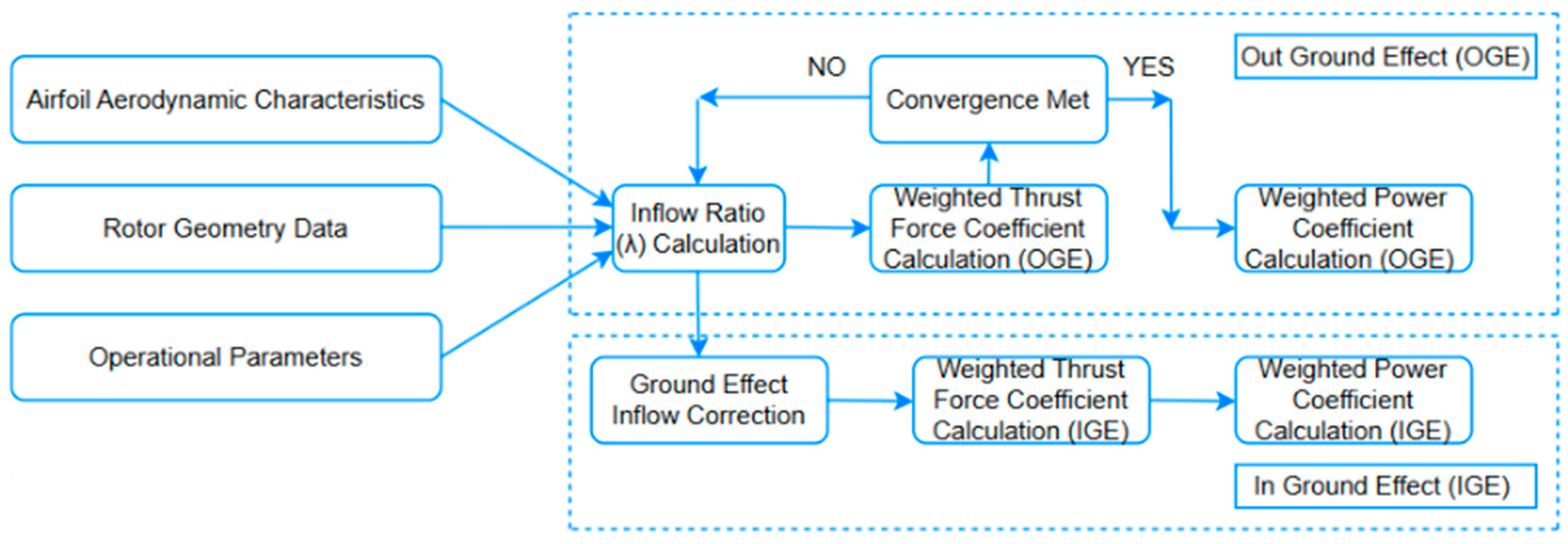
3. Calculation Procedure
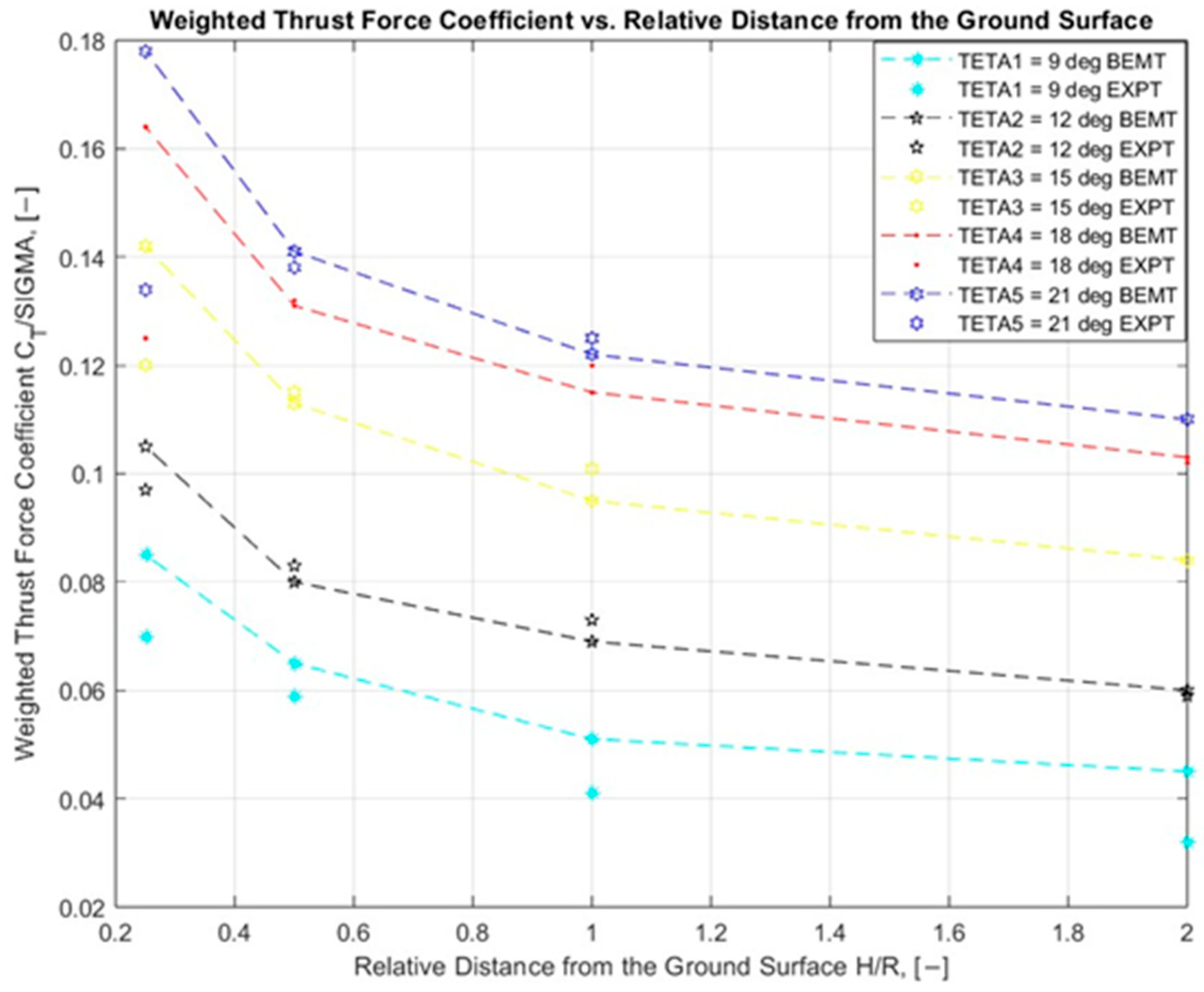
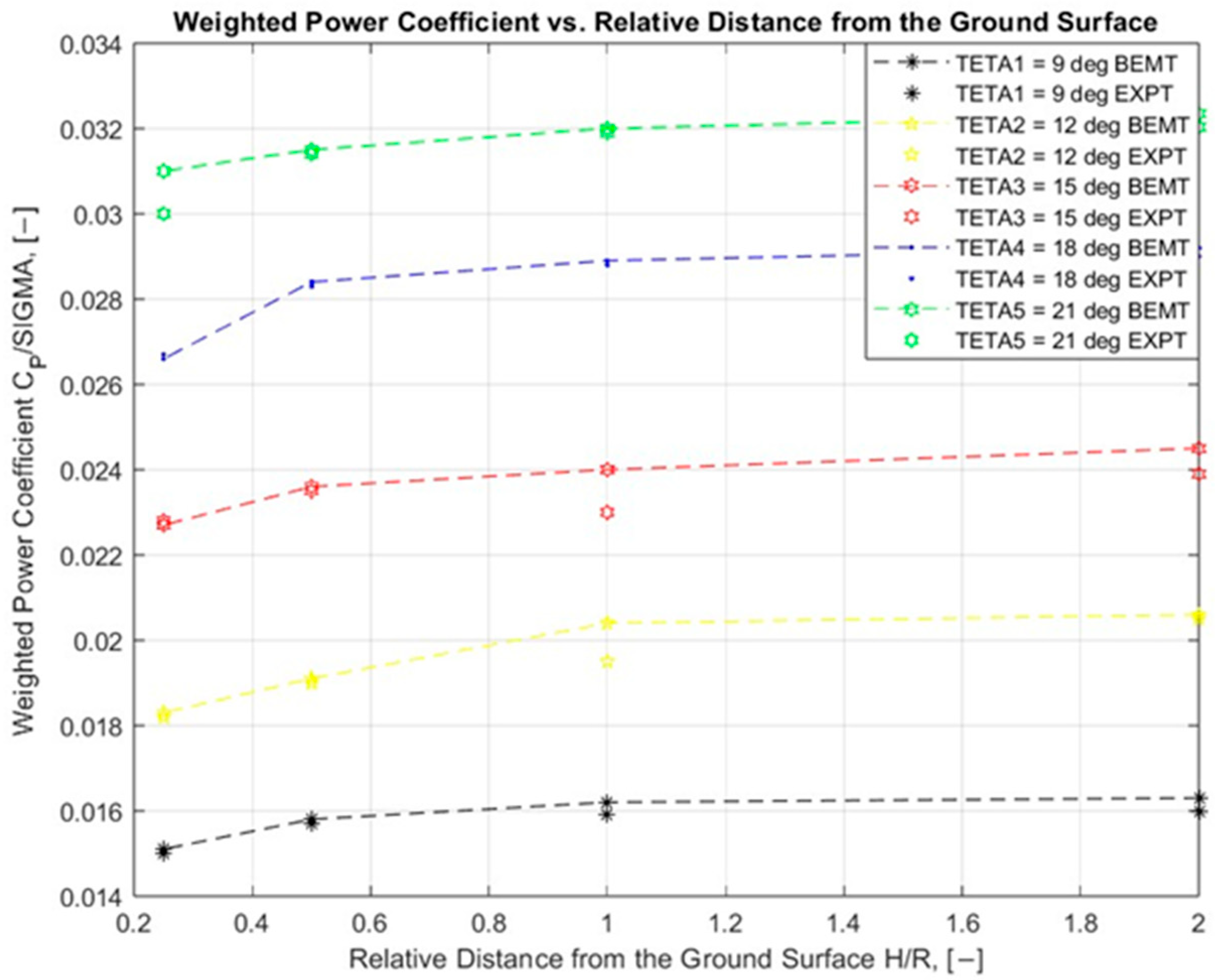
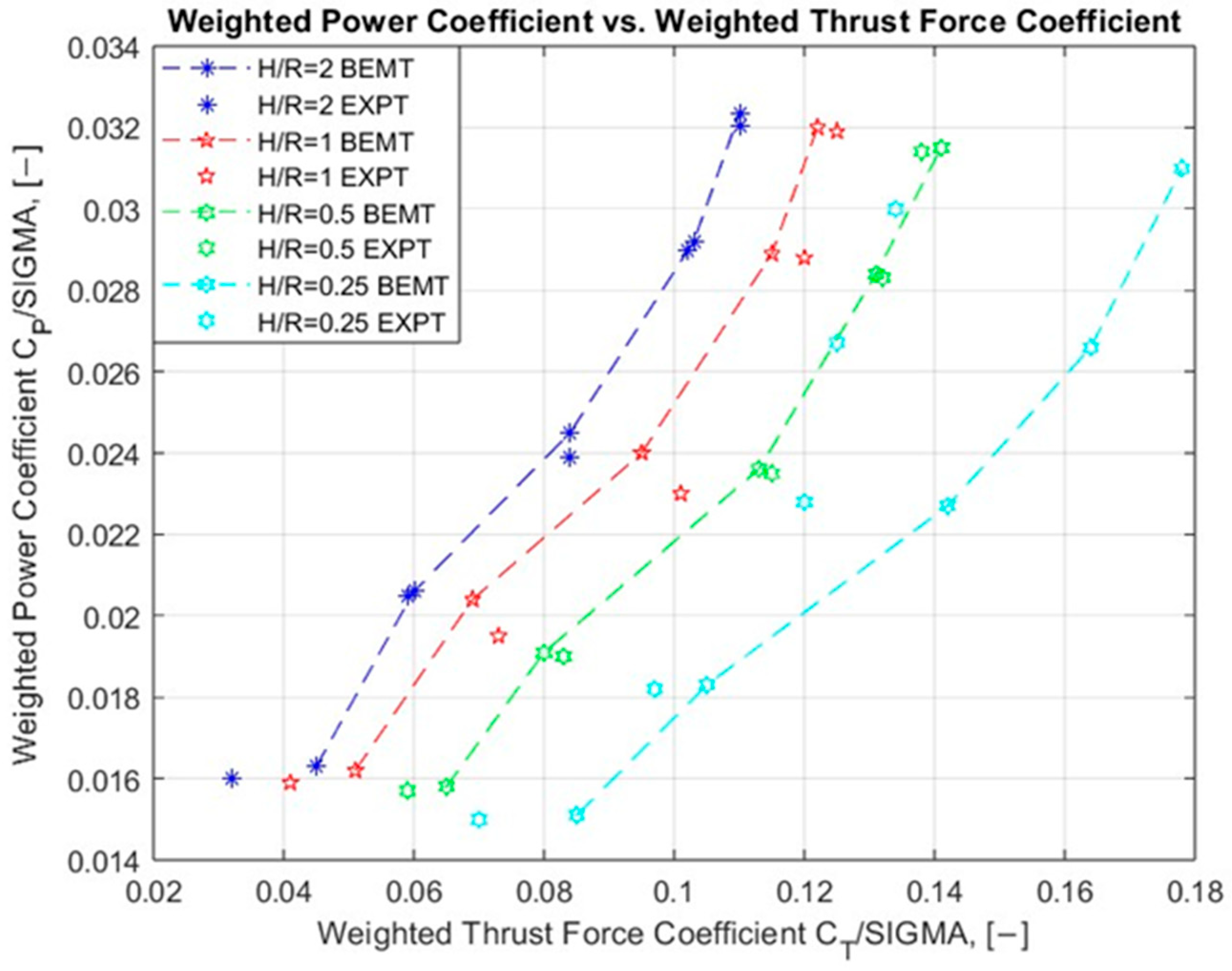
The calculation procedure aims to evaluate the weighted power coefficients’ values C P σ , varying several parameters such as the collective pitch angles (θ) and the relative distances from the ground surface H R , to relate them to the previously calculated weighted thrust force coefficients C T σ by applying a coupled empirical blade element–momentum algorithm, generally represented in Figure 2. The applied algorithm estimates the inflow ratio (λ) distribution in the helicopter rotational plane, taking into consideration the airfoil aerodynamic characteristics, the rotor geometry, and operational parameters by finding a proper angle of attack (α) distribution in the blade’s radial direction. The aerodynamic dependencies between the lift force coefficient C L and the angle of attack (α): C L = f α , the drag force coefficient C D and the angle of attack α :   C D = f α , the aerodynamic polars C L = f C D , the pitch moment coefficient ( C m ) correlation with the angle of attack α : C m = f α , etc., represent the main aerodynamic properties regarding the applied airfoil. After the successful definition of the aerodynamic dependencies, the rotor’s general geometric parameters must be defined. The rotor’s radius (R), the number of blades (N), the rotor’s disk area (A), the chord length (c), the rotor’s solidity (σ), etc., along with the air parameters including the air density ρ , the speed of sound (a), and the dynamic viscosity (μ), have been directly applied in the following computations. The helicopter rotor applied consists of three blades (N = 3) with a radius R = 0.266 m. In addition, several operational parameters with respect to the computational process have been defined for the purpose of deriving the rotor’s aerodynamic characteristics, including the rotor’s operational weight (W) and the rotor’s rotational frequency (n). In the computational case applied, the rotational frequency is chosen as n = 950 rpm. The applied algorithm poses the main objective to evaluate the inflow distribution in the rotor’s rotational plane, based on finding a proper angle of attack α distribution by comparing both the required and the mathematically derived weighted thrust force coefficients C T σ for a hovering state both outside of the ground effect zone and inside it, as represented in Figure 2.
When the convergence tolerance is achieved, the weighted thrust force coefficients C T σ outside of the ground effect (OGE) zone can be directly calculated. An empirical correction is further applied for the sake of finding the C T σ values in ground effect (IGE) conditions. Once the weighted thrust force coefficients C T σ are evaluated for both the OGE and the IGE conditions, the coefficients of weighted induced power C P i σ can be estimated.
As a result, the full weighted power coefficients C P σ can be computed. The major steps in the computational empirical blade element–momentum algorithm are represented in Figure 2, above. Eventually, the dependencies between the mathematically estimated weighted power coefficients C P σ , the collective pitch angles (θ), and the relative distances from the rotational plane to the ground surface H R   are plotted, and the rotor characteristics in ground effect conditions can be successfully quantified. Comparisons with the weighted thrust force coefficients C T σ are also conducted.

4. Results

The proposed calculation methodology is applied for the purpose of calculating the weighted thrust force C T σ and the weighted power coefficients C P σ for the 3-bladed helicopter rotor with a radius R = 0.266 m, which is represented above. Following the weighted thrust force coefficients calculation C T σ and their corresponding depiction, varying the collective pitch angle (θ) at different relative distances to the ground surface H R , an additional transformation should be conducted in order for the ground effect zone to be identified. The ground effect zone can be characterized once the weighted thrust force coefficients C T σ are presented as a function of the relative distance from the ground H R . Figure 3 shows the dependencies between the relative thrust force coefficients C T σ and the relative distances from the ground surface H R , varying the collective pitch angles (θ) both experimentally and numerically by applying the empirical BEMT algorithm.
When the helicopter rotor operates at small distances from the ground plane, a corresponding increase in the generated weighted thrust force coefficients C T σ are observed, and a rise in the calculated values at each collective pitch angle (θ) can be observed, as well. Moreover, at every fixed relative distance from the rotor plane of rotation to the ground surface H R , decreasing the collective pitch angle (θ) leads to a corresponding decline in the experimental and in the numerical values of the weighted thrust force coefficients C T σ . Operating at a collective pitch angle θ = 9°, the rotor’s calculated weighted thrust force coefficient C T σ follows an exponential trend, starting from approximately 0.065 at the relative distance from the ground surface H R = 0.5 up to 0.045 at the relative distance H R = 2 . Rotating at a collective pitch angle θ = 12°, the airscrew’s generated weighted thrust coefficient C T σ experiences an increase, from 0.059 at the relative distance H R = 2 to approximately 0.083 at the relative distance H R = 0.5 , while the numerical values variate from approximately 0.06 at H R = 2 to 0.08 at H R = 0.5 . A further increase in the calculated collective pitch angle (θ) up to 21° leads to a corresponding rise in the calculated weighed thrust force coefficient C T σ to 0.141 at H R = 0.5 and then follows a downward trend to reach the value of 0.110 at H R = 2 .
The results, depicted in Figure 3, illustrate the ground effect zone length. According to the data presented in Figure 3, the ground effect zone for all the collective pitch angles (θ) lies between the rotor plane of rotation and the relative distance H R = 2 , with an intensive change in the relative thrust force coefficients C T σ at distances of up to H R = 1 . For all the collective pitch angles (θ), except the collective pitch angles at H R < 0.25 , the estimated relative thrust force coefficients’ values C T σ show a reasonable agreement with the experimentally obtained data, covering an error of up to 5%.
A decrease in the relative distance from the ground surface H R leads to an increase in the shift between the experimental and the numerical values. This effect happens due to the inability of the applied empirical models to accurately predict the weighted thrust force coefficients’ values C T σ when the helicopter rotor operates in the extreme ground effect zone.
The successful weighted thrust force coefficient value C T σ quantification requires the next step in the rotor analysis—the calculation of the weighted power coefficients C P σ , varying the collective pitch angles (θ) and the relative distances from the ground surface H R . Power coefficient ( C P ) estimation requires the consequent evaluation of the zero-power coefficients ( C P 0 ) and the induced power coefficients ( C P I ) . In detail, the induced power coefficients ( C P I ) can be evaluated directly, considering the coefficients of thrust ( C T ), while the zero-power coefficients ( C P 0 ) can be calculated from the aerodynamic characteristics of the applied airfoil, considering a correction to compensate for the low-Reynolds-number effects.
Table 1 represents the experimentally obtained and the numerically calculated weighted power coefficients C P σ as a function of the collective pitch angles (θ) and the relative distances from the ground surface H R . The values represented in Table 1 can be graphically plotted.
As a result, Figure 4 illustrates the correlation between the weighted power coefficients C P σ and the collective pitch angles (θ), varying the relative distances from the ground surface H R . An increase in the collective pitch angle (θ) leads to a corresponding rise in the weighted power coefficients C P σ for each individual relative distance from the ground surface H R . Operating at a fixed collective pitch angle (θ), the rotor requires less power if it rotates at smaller distances from the ground surface H R , and the weighted power coefficients C P σ values are lower, as well.
The effect caused by the collective pitch angle (θ) and the relative distance from the surface H R on the weighted power coefficients C P σ is hard to estimate and is distinguished in Figure 4. However, the numerical results presented after applying the empirical BEMT algorithm show considerably good agreement with the previously obtained experimental results.
Operating at a collective pitch angle θ = 9° and H R = 0.5, the rotor requires a weighted power coefficient C P σ = 0.016, rising to a height of 0.032 at a collective angle θ = 21°, and virtually doubles its value.
Moreover, when the airscrew operates at θ = 12°, a decrease in the relative operational distance from the ground surface from H R = 2 to H R = 0.5 leads to a decline in both the experimental and numerical weighted power coefficients results C P σ , from approximately 0.0205 to 0.0190, respectively. When the helicopter rotates in the ground effect zone at a collective pitch angle θ = 21°, at the relative distance from the ground surface H R = 0.5 , the required weighted power coefficient for hovering is equal to approximately 0.0315, then the weighted power coefficient value increases to the magnitude of approximately 0.0320 at the relative distance from the ground surface H R = 2 .
Additionally, Figure 5 represents the correlations between the weighted power coefficients’ values C P σ vs. the relative distances from the ground surface H R , varying the collective pitch angle (θ) both experimentally and numerically. An increase in the collective pitch angle (θ) requires more power for rotation. When the helicopter rotor rotates with a collective pitch angle θ = 9 ° , the experimentally derived and the numerically evaluated weighted power coefficient C P σ is equal to approximately 0.016 at H R = 0.5 ; further, it rises to about 0.0315 at H R = 2 . Operating at the relative distance from the ground surface H R = 2 , the rotor’s weighted power coefficient C P σ remains unaffected by the presence of the ground surface beneath it, from approximately 0.016 at θ = 9 ° to approximately 0.032 at θ = 21 ° . The dependencies presented below show that the ground effect zone lies in the length between the plane of rotation and a distance of up to 2R. However, comparing both the C T σ and the C P σ with the H R correlations, varying the collective pitch angle (θ), the C P σ vs. the H R can barely be quantified and distinguished. The numerical results presented show considerably good agreement with the numerical results previously obtained.
Eventually, the dependencies between the weighted power coefficients C P σ and the weighted thrust force coefficients C T σ varying the distances from the ground surface H R and the blade collective pitch angle (θ) can be depicted. The results in Figure 6 represent both the numerical and the experimental quantifications and follow a second-order curve path, varying the collective pitch angle (θ).
An increase in the collective pitch angle (θ) leads to a higher weighted thrust force coefficient C T σ and requires more weighted power coefficients C P σ to keep the rotation going. For every given constant weighted thrust coefficient C T σ , a decrease in the operational distance from the helicopter’s disk to the ground surface requires less power for rotation and consequently a lower weighted power coefficient C P σ . The results, presented in Figure 6, show that a decrease in the relative operational distance H R results in the curves moving downwards in the right direction.
The overall dependency between the C P σ and the C T σ , varying the blade collective pitch angle (θ) and the relative distance from the ground H R , presented in Figure 6, also illustrate the deviation between the experimental and the numerical values, especially when the helicopter rotor operates close to the ground surface. In detail, the deviation originates from the inability of the applied empirical models to predict the aerodynamic coefficients at distances from the ground lower than 0.25R.
However, despite the deviations, the correlations in Figure 6 fully describe the rotor aerodynamic performance in the ground effect zone and the capability of the applied coupled empirical blade element–momentum model to evaluate the helicopter rotor performance in the ground effect zone.

5. Conclusions

In conclusion, this article represents a study that quantifies the helicopter rotor aerodynamic performance in ground effect conditions, with a focus on estimating the power required, represented through the weighted power coefficient values C P σ . The dependencies between the weighted power coefficients C P σ and the relative distances from the ground surface H R , varying the collective pitch angle (θ), are derived. An increase in the relative operational distance from the helicopter rotor plane to the ground surface H R leads to a consequent rise in the required weighted power coefficient in ground effect conditions C P σ for every constant collective pitch angle (θ), conversely to the weighted thrust force coefficients C T σ values. Moreover, our investigation successfully estimated that, when the rotor collective pitch angle (θ) increased, the rotor would require more power to rotate and the weighted power coefficients’ values C P σ would constantly increase for every relative distance from the rotational plane to the ground surface H R . The ground effect zone can be estimated, considering both the thrust and power magnitudes, to be equal to H R = 2 for all the evaluated cases. On the other hand, the correlations between the weighted power C P σ and the weighted thrust force coefficients C T σ , varying the relative distance from the ground surface H R and the collective pitch angle (θ), illustrate a deviation between the numerical and the experimental results for the relative operational distances H R < 0.25 due to the inability of the applied empirical correction to accurately predict the magnitudes in extreme ground effect conditions. However, the applied algorithm fulfills the main aim of this research, i.e., to estimate the aerodynamic characteristics of the examined helicopter rotor in ground effect conditions, and can be applied as a tool in making performance predictions.

Funding

The author would like to thank the Research and Development Sector of the Technical University of Sofia for sponsoring the publication of this article.

Institutional Review Board Statement

Not applicable.

Informed Consent Statement

Not applicable.

Data Availability Statement

Data contained within the article are available upon request.

Acknowledgments

This research is conducted with the support of the Bulgarian–American Commission for Educational Exchange Fulbright within a collaboration with the University of Maryland in College Park.

Conflicts of Interest

The author declares no conflicts of interest.

References

  1. Knight, M.; Hefner, R. Analysis of Ground Effect on the Lifting Airscrew; NACA Technical Note 835; NASA: Washington, DC, USA, 1941.
  2. Fradenburgh, E. The Helicopter and the Ground Effect Machine. J. Am. Helicopter Soc. 1960, 5, 24–33. [Google Scholar] [CrossRef]
  3. Heyson, H. Ground Effect for Lifting Rotors in Forward Flight; National Aeronautics and Space Administration Technical Note D-234; NASA: Washington, DC, USA, 1960. [Google Scholar]
  4. Rotaru, C.; Todorov, M.B. Helicopter Flight Physics. In Flight Physics Models Techniques and Technologies; IntechOpen: Rijeka, Croatia, 2017. [Google Scholar] [CrossRef]
  5. Johnson, W. NASA Design and Analysis of Rotorcraft Theory, Release 1.14; NASA Ames Research Center: Washington, DC, USA, 2019. [Google Scholar]
  6. Xin, H.; Prasad, J.; Peters, D.; Itoga, N.; Iboshi, N.; Nagashima, T. Ground Effect Aerodynamics of Lifting Rotors Hovering Above Inclined Ground Plane. In Proceedings of the 17th Applied Aerodynamics Conference, Norfolk, VA, USA, 28 June–1 July 1999. [Google Scholar] [CrossRef]
  7. Gibertini, G.; Grassi, D.; Parolini, C.; Zagaglia, D.; Zanotti, A. Experimental Investigation on the Aerodynamic Interaction Between a Helicopter and Ground Obstacles. Proc. Inst. Mech. Eng. Part G J. Aerosp. Eng. 2014, 229, 1395–1406. [Google Scholar] [CrossRef]
  8. Georgiev, G.; Serbezov, V.; Todorov, M. Experimental Study of Multicopter Propeller Performance near the Ground at Different Inclination Angles. In Proceedings of the 13th International Scientific Conference on Aeronautics, Automotive and Railway Engineering and Technologies (BulTrans-2021), Sozopol, Bulgaria, 10–13 September 2021. [Google Scholar] [CrossRef]
  9. Georgiev, G.; Panayotov, F.; Serbezov, V.; Todorov, M. Experimental Study of Static Characteristics of a Helicopter Rotor in Ground Effect. In Proceedings of the 11th International Scientific Conference “TechSys 2022”—Engineering, Technologies and Systems, Plovdiv, Bulgaria, 26–28 May 2022. [Google Scholar] [CrossRef]
  10. Misiorowski, M.; Rothacker, B.; Cesnik, C. Extreme Ground Effect Characterization Testing for Human-Powered Helicopter Application. In Proceedings of the American Helicopter Society Forum 69, Phoenix, AZ, USA, 21–23 May 2013. [Google Scholar]
  11. Young, L. Simulated Tiltrotor Aircraft Operation in Close Proximity to a Building in Wind and Ground-Effect Conditions. In Proceedings of the 15th AIAA Aviation Technology, Integration, and Operations Conference, Dallas, TX, USA, 22–26 June 2015. [Google Scholar] [CrossRef]
  12. Bauknecht, A.; Schwarz, C.; Raffel, M.; Mailänder, S. Flow Measurement Techniques for Rotor Wake Characterization on Free-Flying Helicopters in Ground Effect. In Proceedings of the AIAA Scitech 2019 Forum, San Diego, CA, USA, 7–11 January 2019. [Google Scholar] [CrossRef]
  13. Kinzel, M.; Cornelius, J.; Schmitz, S.; Palacios, J.; Langelaan, J.; Adams, D.; Lorenz, R. An Investigation of the Behavior of a Coaxial Rotor in Descent and Ground Effect. In Proceedings of the AIAA Scitech 2019 Forum, San Diego, CA, USA, 7–11 January 2019. [Google Scholar] [CrossRef]
  14. Light, J. Tip Vortex Geometry of a Hovering Helicopter Rotor in Ground Effect. In Proceedings of the American Helicopter Society Annual Forum, Boston, MA, USA, 22–24 May 1989. [Google Scholar]
  15. Hanker, E.; Smith, R. Parameters Affecting Helicopter Interactional Aerodynamics in Ground Effect. J. Am. Helicopter Soc. 1985, 30, 52–61. [Google Scholar] [CrossRef]
  16. Silva, P.; Tsoutsanis, P.; Antoniadis, A. Numerical Investigation of Full Helicopter with and without the Ground Effect. Elsevier Aerosp. Sci. Technol. 2022, 122, 107401. [Google Scholar] [CrossRef]
  17. Gao, H.; Agarwal, R. Numerical Study of a Hovering Helicopter Rotor Blade in Ground Effect. In Proceedings of the AIAA Scitech 2019 Forum, San Diego, CA, USA, 7–11 January 2019. [Google Scholar] [CrossRef]
  18. Johnson, W. Rotorcraft Aeromechanics; Cambridge University Press: New York, NY, USA, 2013. [Google Scholar]
  19. Hayden, J. The Effect of the Ground on Helicopter Hovering Power Required. In Proceedings of the AHS 32nd Annual Forum, Washington, DC, USA, 10–12 May 1976. [Google Scholar]
  20. Cheeseman, I.; Bennett, W. The Effect of the Ground on a Helicopter Rotor in Forward Flight; Aeronautical Research Council: London, UK, 1955. [Google Scholar]
Figure 1. Blade element aerodynamics.
Engproc 100 00013 g001
Figure 2. Computational algorithm flow diagram.
Engproc 100 00013 g002
Figure 3. Weighted thrust force coefficient C T σ vs. the relative distance from ground H R at rotational frequency n = 950 rpm, varying the collective pitch angle (θ). Numerical and experimental results.
Engproc 100 00013 g003
Figure 4. Weighted power coefficient C P σ vs. the collective pitch angle (θ) at rotational frequency n = 950 rpm, varying the relative distance to ground H R . Numerical and experimental results.
Engproc 100 00013 g004
Figure 5. The weighted power coefficient C P σ vs. the relative distance from the ground H R at a rotational frequency n = 950 rpm, varying the collective pitch angle (θ). Numerical and experimental results.
Engproc 100 00013 g005
Figure 6. The weighted power coefficient C P σ vs. the weighted thrust coefficient C T σ at a rotational frequency n = 950 rpm, varying the relative distance from the ground H R and the collective pitch angle (θ). Numerical and experimental results.
Engproc 100 00013 g006
Table 1. Weighted power coefficient C P σ vs. the relative distance from the ground H R at the rotational frequency n = 950 rpm, varying the collective pitch angle (θ). Numerical and experimental results.
Weighted   Power   Coefficient   ( C P / σ )
EXPBEMEXPBEMEXPBEMEXPBEMEXPBEM
H/R θ 1 = 9 ° θ 2 = 12 ° θ 3 = 15 ° θ 4 = 18 ° θ 5 = 21 °
20.01600.01630.02050.02060.02390.02450.02900.02920.032030.03234
10.01590.01620.01950.02040.02300.02400.02880.02890.03190.0320
0.50.01570.01580.01900.01910.02350.02360.02830.02840.03140.0315
0.250.01500.01510.01820.01830.02280.02270.02670.02660.03000.0310
Disclaimer/Publisher’s Note: The statements, opinions and data contained in all publications are solely those of the individual author(s) and contributor(s) and not of MDPI and/or the editor(s). MDPI and/or the editor(s) disclaim responsibility for any injury to people or property resulting from any ideas, methods, instructions or products referred to in the content.

