Proceeding Paper

Mechanically Flexible Fluid Flow Sensor for Macro-Tubular Architectures †

1
mmh Labs, Electrical Engineering, Computer Electrical Mathematical Science and Engineering Division, King Abdullah University of Science and Technology (KAUST), Thuwal 23955, Saudi Arabia
2
Advanced Sensors, Oil and Gas Network Integrity, Research and Development Center, Saudi Aramco, Dhahran 31311, Saudi Arabia
3
EE, King Fahd University of Petroleum and Minerals (KFUPM), Dhahran 31261, Saudi Arabia
4
EECS, University of California, Berkeley, CA 94720, USA
*
Author to whom correspondence should be addressed.
Presented at the 8th International Electronic Conference on Sensors and Applications, 1–15 November 2021; Available online: https://ecsa-8.sciforum.net.
Eng. Proc. 2021, 10(1), 76; https://doi.org/10.3390/ecsa-8-11330
Published: 1 November 2021

Abstract

:
Flow sensors are essential for a variety of applications in fluidic industries. This paper proposes a liquid flow sensor using a microfluidic channel for macrotubular architectures. The sensor comprised a firm poly(methyl methacrylate) (PMMA) microfluidic channel bridge on a mechanically flexible polydimethylsiloxane (PDMS) platform installed on the inner wall of tubular systems. The flexible platform was compatible with various tubular architectures and adopted curvatures. In addition, the microscale fluidic channel surpassed the primary disadvantages of common bulky and rigid flowmeters that cause flow streams disturbance and significant pressure drops in tubular systems. Moreover, the microchannel flow sensor is based on detecting the dominated dynamic pressure generated from the fluid velocity inside the microchannel since the tube flow rate is proportional to the flow velocity inside the channel. The pressure sensors for the microchannel flowmeter displayed a sensitivity of 10 pF/kPa and were fabricated inside the PDMS platform. In particular, the pressure was measured using a capacitive pressure sensor owing to its compatibility with flexible electronics and low power consumption. The capacitive pressure sensor inside the microchannel measures the flowrate based on the force generated on the internal walls from the fluid flow velocity inside the channel. Furthermore, the flow sensor behavior was studied for the overall tubular system and validated using a simulation model for volume flow rate ranging from 500 to 2000 mL/min.

1. Introduction

Flow rate measurements in macro-tubes such as pipes are vital for determining the performance of applications in several industries, including the agricultural, oil and gas [1,2], chemicals [3], water transportation, and desalination [4,5] industries. In addition, the measurement of flow rates is an essential requirement in product quality control [6], process analysis, efficient energy management, and material utilization such as waste reduction, yield accounting, and consumption in fluidic industries [7,8].
The growth of fluidic industries has introduced various types of flow-rate sensing techniques for tubular systems. Certain prominent technologies include pressure-difference-based flowmeters [9,10] thermal [11,12] and turbine flowmeters [13,14], electromagnetic [15,16], vortex [17,18], ultrasonic sensors [19,20,21], and Coriolis flowmeters [22,23,24]. However, these types of flow sensors are bulky, rigid, and incompatible with the curvature of tubular architectures. Therefore, they significantly interrupt the fluid velocity, causing permanent and notable pressure drops [21], except for non-invasive flowmeters such as ultrasonic and electromagnetic sensors that are attached onto the outside wall of a pipe. However, magnetism-based flowmeters are not suitable for most of the fluids owing to their limitations in detecting only electrically conductive fluids. In addition, ultrasonic flowmeters are large and pose difficulties in conducting accurate measurements [9]. Unlike Coriolis flowmeters that provide precise measurements, ultrasonic flowmeters are relatively expensive and generate huge pressure drops in fluid flow [25]. Although various types of pipe flowmeters are available, the development and improvement of flow sensors is required because each type poses certain limitations.
One of the methods for resolving the abovementioned issues involve the utilization of microsensors in tubular systems. In the past decades, robust microfluidic flow sensors have been developed for measuring flow rates in small volumes, such as in biomedical and analytical chemistry applications [26,27]. Such microflow sensors are based on MEMS [28,29,30], optical [31,32,33], thermal [34,35,36,37], or pressure-based measurement flow sensing technology [38,39,40,41]. Moreover, the use of microfabrication sensors provides several advantages such as increasing reliability, performance, functionality, and lowering the cost by reducing device dimensions [42]. Therefore, utilizing the advantages of microfluidic sensors in tubular systems can surpass the main challenges of the existing flow sensors.
In this study, we introduce a novel liquid volumetric flowmeter for macro-tubular systems. The designed microfluidic flow sensor has a channel installed on the inner wall of a tubular system, and it comprises a mechanically flexible platform that is compatible with varying curvature architectures and tube diameters. Additionally, the height of the microscale device ensures low flow-disturbance and pressure drop in the tubular system, owing to its minor volume occupation. Furthermore, the tubular flow rate is proportional to the microchannel flow rate as well as the pressure generated on the channel walls. The variation in pressure was detected by modeling at selected points on the channel walls, and experimentally using capacitive pressure sensors located below the channel.

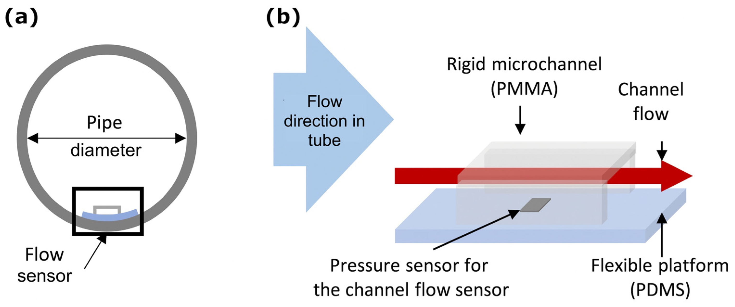
2. Materials and Design

The designed microfluidic flow sensor has a channel installed on the inner wall of a tubular system, and it comprises a mechanically flexible platform that is compatible with varying curvature architectures and tube diameters, as shown in Figure 1. The height of the microscale device ensures low flow-disturbance and pressure drop in the tubular system owing to its minor volume occupation. The variation in pressure was detected by modeling at selected points on the channel walls and experimentally using capacitive pressure sensors located below the channel. Figure 1a displays the cross-sectional area of a tube with a microchannel flow sensor attached to its inner wall. The designed structure and the materials selected for the sensor are presented in Figure 1b. The proposed flow sensor design does not require an external flow path or tube contraction to prevent fluid flow interruption, pressure drop, and energy loss. Instead, the sensor utilizes the volumetric flow rate generated inside the tubular system to drive a small fluidic volume inside the microsensor with the advantages of microfabrication to measure volumetric flow rate under laminar flow conditions.
The capacitive pressure sensor inside the microchannel measured the absolute pressure generated from the weight force and flow velocity of the fluid inside the channel. The pressure measured using the capacitive pressure sensor constitutes the total pressure ( P T o t a l ), including both static pressure and dynamic pressure expressed in Equation (1) [43]. In addition, the dynamic pressure is proportional to the square of the volumetric flow rate (Q) of a fluid expressed in Equation (2), where ρ denotes the fluid density, h represents the channel depth, and g is the gravitational acceleration.
P T o t a l = P S t a t i c + P D y n a m i c
P T o t a l = ρ   h   g + 1 2 ρ Q   2 A 2

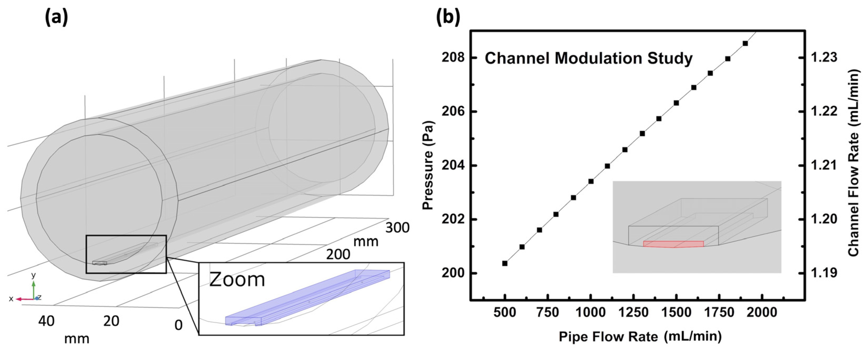
3. Simulation and Modulation

The operating principle of the flexible-platform flow sensor was studied based on simulation conducted using the commercially available tool COMSOL™. A model analysis was performed to understand the relationship between the channel and tubular flow rates and to ensure that flow conditions inside the channel were completely developed, which replicated the fluid flow dynamics inside a 3-dimensional (3D) sensory system based on the Navier–Stokes equation. The finite element analysis was set with default discretization for laminar flow as a linear interpolation between the velocity and pressure to simplify the computational process and reduce the computation time. The channel dimensions were set to 250 μ m high, 3 mm wide, and 60 mm long. The designed channel was attached to the internal wall of a tube with an inner diameter of 3.8 cm, as portrayed in Figure 2a. In particular, three locations were selected inside the inner wall of the microchannel to simplify the calculations, and the pressure measurements were recorded at the selected sites.
The simulation results of the flow sensor are presented in Figure 2b. In this study, we used model analysis to determine the correlation between the tubular flow rate and microchannel flow rate, followed by recording the pressure range at the selected sites inside the channel. As expected from network piping physics calculations [44], the flow rate in the tube system was proportional to the flow rate in the microfluidic channel, because the total flow rate was equal to the summation of flow rates in the individual branches. Although the results exhibited that the tube flow rate was linearly proportional to the total pressure at the selected locations, in reality, the linear interpolation between velocity and pressure was set in the simulation for obtaining approximate results with less complex computational process and time. Moreover, the dynamic pressure varied as a function of the fluid velocity or flow rate. Consequently, the tubular flow rate was related to the microchannel flow rate as well as the dynamic pressure generated on the channel walls.

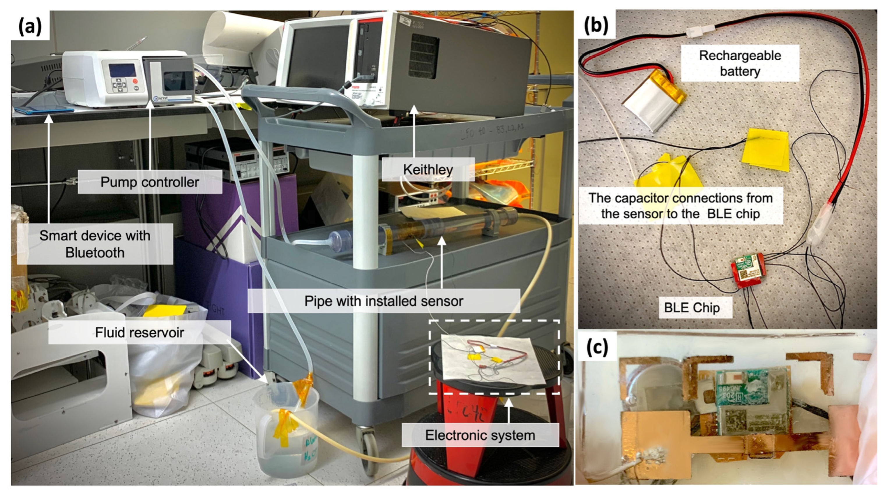
4. Fabrication and Characterization

Figure 3 demonstrates the fabrication process of the flow sensor. Initially, the capacitive pressure sensor on the flexible PDMS platform was fabricated and characterized before completing the fabrication process to validate the operating conditions of the capacitive pressure sensor. It was fabricated similar to the previous reported work [45]. The pressure sensor was characterized at water depths varying from 0–65 cm at 5 cm intervals. The values for the three capacitance pressure sensors were recorded at various water depths using the Keithley (model 4200A-SCS) at 10 kHz as an optimized selected frequency to obtain the best signal-to-noise ratio. Thereafter, the average capacitance readings at each depth were calculated. The pressure sensors were characterized on a flat surface and concave surface position using a 3.8 cm bending diameter. The pressure sensor results in the flexible platform indicated that the capacitance was linearly proportional to the applied pressure and depth, as depicted in Figure 3a. In addition, both the characterization results for various surface conditions, i.e., concave and flat surfaces, displayed a similar pressure sensitivity of 10 pF/kPa. The designed device exhibited almost identical behavior under flat and concave surface positions, excepting that the initial capacitance value was slightly higher at the concave position owing to the stress generated from the mechanical deformation of the flexible sensory platform. For both the positions, the initial reading at 0 kPa displayed the maximum errors, because the depth value varied in comparison to that at other locations in the experiment, and this site was located outside the water tank, where the density varied as well.
As depicted in Figure 3b, a microchannel bridge was fabricated using a PMMA sheet of 1 mm thickness. The channel bridge was attached to the prepared, flexible, sensory platform using oxygen plasma bonding, as demonstrated in Figure 3c. The device was repackaged with a thin PDMS coat to ensure appropriate bonding between the channel and platform. The flow sensor was characterized after the microfluidic channel was attached to the flexible sensory platform. A laboratory-grade, transparent, polyvinyl chloride pipe system was constructed with an inner diameter of 3.8 cm and a total system length of 60 cm. The device was installed on the inner tube wall located beyond the hydrodynamic entrance at 15 cm from the entrance expansion. The pipe system was appropriately encapsulated with caps and secured with epoxy glue.
The volumetric flow sensor was characterized using a pump controller (Catalyst FH100DX pump) for generating a precise flow rate. The pump was connected to the pipe and fluid reservoirs. The flow sensor was tested with water at various flow rates ranging from 0–2000 mL/min. Each flow rate was maintained for 1 min to ensure a stabilized flow prior to acquiring the data. In addition, the capacitance was recorded at each flow rate from three pressure sensors using a Keithley. Subsequently, ΔC/Co was calculated for each capacitance, where C and Co are the capacitance values with and without the applied pressure, respectively. Finally, the three calculated ΔC/Co values were averaged for each flow rate. In particular, determining the average for the capacitance reading between the three selected sites aided in smoothing the graph plots and create a single graph to correlate the recorded capacitance values in comparison to the tubular flow rate, because all the three pressure sensors increased proportionally. Finally, the setup was disassembled after the experiment, and the device was diagnosed to ensure a complete fluid seal in the device.
The flowmeter sensor was developed as a standalone system for real-time and wireless monitoring applications, illustrated in Figure 4. The characterization setup and electronic components for the wireless monitoring system are as expressed in a previous work [45]. Various flow rates were examined through a pipe system using a pump controller. Moreover, the data were wirelessly transmitted using Bluetooth and recorded using an Android smart device installed with a specially developed in-house application to inspect the fluid flow rates with the developed flowmeter.

5. Results and Discussion

The results of the flow sensor operating under various flow rate conditions are depicted in Figure 3d, which suggest the relationship between the capacitance measured by the pressure sensor and the flow rate in the microchannel and tubular system. Moreover, the tubular flow rate was proportional to the channel flow rate and validated with the simulation model. Furthermore, the pipe flow rate and evaluated ΔC/Co exhibited incremental curved behavior, and the results indicated that the device was sensitive in the range of 500–2000 mL/min, because the force occurring in flow rates below 500 mL/min is not adequate to drive the fluid inside the microchannel for the given channel dimensions. More precisely, the variation in pressure was lesser than the pressure sensitivity range. Additionally, the flow rate was not tested above 2000 mL/min owing to pump limitation.
Flowmeter characterization experiment for real-time monitoring is presented in Supplementary Video S1, and the sensor response results versus time at various flow rates for a 50% diluted glycerol solution are depicted in Figure 5a. The y-axis denotes the output response from the BLE PSoC in the raw capacitive to digital convertor values. The relationship between the capacitive pressure sensor and the raw output values has been illustrated. Furthermore, the trend of the raw output averaged values at each tested flow rate for the diluted glycerol solutions are presented in Figure 5b.

6. Conclusions

In summary, we reported a novel liquid volumetric flow sensor and analyzed it based on simulations and modeling. In addition, we fabricated the designed flow sensor using a lithography-free technique and demonstrated its operational performance. Consequently, the model analysis results corresponded well with the experimental results. The sensor was based on a microfluidic sensing mechanism that utilized the microsensors to measure macro systems as an application of microfluidic sensors. The sensor comprised a rigid microchannel PMMA bridge on a mechanically flexible PDMS substrate to provide flexibility for various tubular dimensions on the inner walls of the pipes with minimum flow perturbations. Therefore, the designed microsensor reduced the pressure drop and energy loss in the pipe flow. Moreover, the microflow sensor measured the absolute pressure using capacitive pressure sensors located under the microchannel. The pressure sensor was fabricated inside a mechanically flexible PDMS platform with a sensitivity of 10 pF/kPa. Furthermore, the operating principle and behavior of the fluid flow sensor were replicated with simulations and verified experimentally at flow rates ranging from 500–2000 mL/min.

Supplementary Materials

The following are available online at https://www.mdpi.com/article/10.3390/ecsa-8-11330/s1, Video S1: The flowmeter characterization experiment for real-time monitoring.

Funding

This research received no external funding.

Institutional Review Board Statement

Not applicable.

Informed Consent Statement

Not applicable.

Data Availability Statement

The data that support the findings of this study are available from the corresponding author upon reasonable request.

Acknowledgments

This study is based on the work supported by King Abdullah University of Science and Technology (KAUST) and the Research and Development Centre of Saudi Aramco.

Conflicts of Interest

The author declares no potential conflict of interest.

References

  1. Zheng, G.B.; Jin, N.D.; Jia, X.H.; Lv, P.J.; Liu, X. Bin Gas-liquid two phase flow measurement method based on combination instrument of turbine flowmeter and conductance sensor. Int. J. Multiph. Flow 2008, 34, 1031–1047. [Google Scholar] [CrossRef]
  2. Rajita, G.; Mandal, N. Review on transit time ultrasonic flowmeter. In Proceedings of the 2016 2nd International Conference on Control, Instrumentation, Energy and Communication, Kolkata, India, 28–30 January 2016; pp. 88–92. [Google Scholar]
  3. Abdul Wahab, Y.; Abdul Rahim, R.; Fazalul Rahiman, M.H.; Ridzuan Aw, S.; Mohd Yunus, F.R.; Goh, C.L.; Abdul Rahim, H.; Ling, L.P. Non-invasive process tomography in chemical mixtures—A review. Sensors Actuators B Chem. 2015, 210, 602–617. [Google Scholar] [CrossRef]
  4. Takashima, S.; Asanuma, H.; Niitsuma, H. A water flowmeter using dual fiber Bragg grating sensors and cross-correlation technique. Sensors Actuators A Phys. 2004, 116, 66–74. [Google Scholar] [CrossRef]
  5. Kabeel, A.E.; Hamed, M.H.; Omara, Z.M.; Sharshir, S.W. Water desalination using a humidification-dehumidification technique—A detailed review. Nat. Resour. 2013, 4, 286–305. [Google Scholar] [CrossRef] [Green Version]
  6. Basu, S.; Debnath, A.K. Power Plant Instrumentation and Control Handbook: A Guide to Thermal Power Plants, 1st ed.; Elsevier: Amsterdam, The Netherlands, 2015; ISBN 9780128009406. [Google Scholar]
  7. Evans, R.P.; Blotter, J.D.; Stephens, A.G. Flow rate measurements using flow-induced pipe vibration. J. Fluids Eng. 2004, 126, 280–285. [Google Scholar] [CrossRef]
  8. Zheng, Y.; Liu, Q. Review of techniques for the mass flow rate measurement of pneumatically conveyed solids. Measurement 2011, 44, 589–604. [Google Scholar] [CrossRef]
  9. Liu, Z.; Hong, T.; Zhang, W.; Li, Z.; Chen, H. Novel liquid flow sensor based on differential pressure method. Rev. Sci. Instrum. 2007, 78, 015108. [Google Scholar] [CrossRef]
  10. Wiklund, J.; Shahram, I.; Stading, M. Methodology for in-line rheology by ultrasound Doppler velocity profiling and pressure difference techniques. Chem. Eng. Sci. 2007, 62, 4277–4293. [Google Scholar] [CrossRef]
  11. Otakane, K.; Sakai, K.; Seto, M. Development of the thermal flow meter. In Proceedings of the SICE 2003 Annual Conference, Fukui, Japan, 6–8 August 2003; pp. 3080–3083. [Google Scholar]
  12. Huijsing, J.H.; Van Dorp, A.L.C.; Loos, P.J.G. Thermal mass-flow meter. J. Phys. E. 1988, 21, 994. [Google Scholar] [CrossRef]
  13. Edwards, P.K. Turbine Flow Monitoring Device. U.S. Patent 6487919, 3 December 2002. [Google Scholar]
  14. Abdullahi, S.I.; Malik, N.A.; Habaebi, M.H.; Salami, A.B. Miniaturized turbine flow sensor: Design and simulation. In Proceedings of the 2018 7th International Conference on Computer and Communication Engineering, Kuala Lumpur, Malaysia, 19–20 September 2018; pp. 38–43. [Google Scholar]
  15. Gianchandani, Y.B.; Takahata, K. Electromagnetic Flow Sensor Device. U.S. Patent 7922667, 12 April 2011. [Google Scholar]
  16. Spong, E.; Reizes, J. Efficiency improvements of electromagnetic flow control. In Proceedings of the CHT-04—Advances in Computational Heat Transfer III. Proceedings of the Third International Symposium; Begell House, Inc.: Danbury, CT, USA, 2004. [Google Scholar] [CrossRef]
  17. Cheng, L.K.; Schiferli, W.; Nieuwland, R.A.; Franzen, A.; den Boer, J.J.; Jansen, T.H. Development of a FBG vortex flow sensor for high-temperature applications. In Proceedings of the 21st International Conference on Optical Fiber Sensors, Ottawa, ON, Canada, 15–19 May 2011; Volume 7753, p. 77536V. [Google Scholar]
  18. Pankanin, G.L. The vortex flowmeter: Various methods of investigating phenomena. Meas. Sci. Technol. 2005, 16, 1–16. [Google Scholar] [CrossRef]
  19. Masasi, B.; Frazier, R.S.; Taghvaeian, S. Review and operational guidelines for portable ultrasonic flowmeters. Oklahoma Coop. Ext. 2017, 1535, 1–8. [Google Scholar]
  20. Li, B.; Lu, J.; Chen, J.; Chen, S. Study on transit-time ultrasonic flow meter with waveform analysis. In Proceedings of the 2nd International Conference on Information System and Data Mining, Lakeland, FL, USA, 9–11 April 2018; pp. 146–150. [Google Scholar]
  21. Lynnworth, L.C.; Liu, Y. Ultrasonic flowmeters: Half-century progress report, 1955–2005. Ultrasonics 2006, 44, 1371–1378. [Google Scholar] [CrossRef] [PubMed]
  22. Liptákg, B.G. Mass Flowmeters, Coriolis. In Instrument Engineers’ Handbook—Process Measurement and Analysis; CRC Press: Boca Raton, FL, USA, 2003; ISBN 978-0849310836. [Google Scholar]
  23. Anklin, M.; Drahm, W.; Rieder, A. Coriolis mass flowmeters: Overview of the current state of the art and latest research. Flow Meas. Instrum. 2006, 17, 317–323. [Google Scholar] [CrossRef]
  24. Bobovnik, G.; Kutin, J.; Bajsić, I. The effect of flow conditions on the sensitivity of the Coriolis flowmeter. Flow Meas. Instrum. 2004, 15, 69–76. [Google Scholar] [CrossRef]
  25. Gorak, A.; Schoenmakers, H. Distillation: Equipment and Processes, 1st ed.; Academic Press: Cambridge, MA, USA, 2014; ISBN 9780123868794. [Google Scholar]
  26. Droogendijk, H.; Groenesteijn, J.; Haneveld, J.; Sanders, R.G.P.; Wiegerink, R.J.; Lammerink, T.S.J.; Lötters, J.C.; Krijnen, G.J.M. Parametric excitation of a micro Coriolis mass flow sensor. Appl. Phys. Lett. 2012, 101, 99–102. [Google Scholar] [CrossRef]
  27. Yao, J.; Takei, M. Application of process tomography to multiphase flow measurement in industrial and biomedical fields: A review. IEEE Sens. J. 2017, 17, 8196–8205. [Google Scholar] [CrossRef]
  28. Huber, C. MEMS-based Micro-Coriolis Density and Flow Measurement Technology. In Proceedings of the AMA Conferences 2015, Nürnberg, Germany, 19–21 May 2015; Volume 83, pp. 157–162. [Google Scholar]
  29. Wu, S.; Lin, Q.; Yuen, Y.; Tai, Y.C. MEMS flow sensors for nano-fluidic applications. Sens. Actuators A Phys. 2001, 89, 152–158. [Google Scholar] [CrossRef] [Green Version]
  30. Wang, Y.; Lee, C.; Chiang, C. A MEMS-based Air Flow Sensor with a Free-standing micro-cantilever Structure. Sensors 2007, 7, 2389–2401. [Google Scholar] [CrossRef] [PubMed] [Green Version]
  31. Yan, S.; Liu, Z.; Li, C.; Ge, S.; Xu, F.; Lu, Y. “Hot-wire” microfluidic flowmeter based on a microfiber coupler. Opt. Lett. 2016, 41, 5680. [Google Scholar] [CrossRef]
  32. Gong, Y.; Qiu, L.; Zhang, C.; Wu, Y.; Rao, Y.J.; Peng, G.D. Dual-mode fiber optofluidic flowmeter with a large dynamic range. J. Light. Technol. 2017, 35, 2156–2160. [Google Scholar] [CrossRef]
  33. Ramírez-Miquet, E.E.; Perchoux, J.; Loubière, K.; Tronche, C.; Prat, L.; Sotolongo-Costa, O. Optical feedback interferometry for velocity measurement of parallel liquid-liquid flows in a microchannel. Sensors 2016, 16, 1233. [Google Scholar] [CrossRef] [PubMed] [Green Version]
  34. Tanaka, H.; Terao, M.; Tanaka, Y. Non-wetted thermal micro flow sensor. In Proceedings of the SICE Annual Conference, Takamatsu, Japan, 17–20 September 2007; pp. 2084–2088. [Google Scholar]
  35. Arevalo, A.; Byas, E.; Foulds, I.G. Simulation of thermal transport based flow meter for microfluidics applications. In Proceedings of the Comsol Conference, Rotterdam, The Netherlands, 9–11 October 2013; Volume 2, pp. 1–5. [Google Scholar]
  36. Ashauer, M.; Scholz, H.; Briegel, R.; Sandmaier, H.; Lang, W. Thermal flow sensors for very small flow rate. In Proceedings of the Transducers ’01 Eurosensors XV, Munich, Germany, 10–14 June 2001; pp. 1436–1439. [Google Scholar]
  37. Kuo, J.T.W.; Yu, L.; Meng, E. Micromachined thermal flow sensors-a review. Micromachines 2012, 3, 550–573. [Google Scholar] [CrossRef] [Green Version]
  38. Oosterbroek, R.; Lammerink, T.; Berenschot, J.; Krijnen, G.; Elwenspoek, M.; Berg, A. A micromachined pressure/flow-sensor. Sensors Actuators A Phys. 1999, 77, 167–177. [Google Scholar] [CrossRef]
  39. Liu, J.; Tai, Y.C.; Ho, C.M. MEMS for pressure distribution studies of gaseous flows in microchannels. In Proceedings of the IEEE Micro Electro Mechanical Systems, Amsterdam, The Netherlands, 29 January–2 February 1995; pp. 209–215. [Google Scholar]
  40. Song, W.; Psaltis, D. Optofluidic membrane interferometer: An imaging method for measuring microfluidic pressure and flow rate simultaneously on a chip. Biomicrofluidics 2011, 5, 44110. [Google Scholar] [CrossRef] [PubMed] [Green Version]
  41. Roh, C.; Lee, J.; Kang, C.K. Physical properties of PDMS (polydimethylsiloxane) microfluidic devices on fluid behaviors: Various diameters and shapes of periodically-embedded microstructures. Materials 2016, 9, 836. [Google Scholar] [CrossRef] [PubMed] [Green Version]
  42. Liu, P.; Zhu, R.; Que, R. A flexible flow sensor system and its characteristics for fluid mechanics measurements. Sensors 2009, 9, 9533–9543. [Google Scholar] [CrossRef] [PubMed] [Green Version]
  43. Munson, B.R.; Okiishi, T.H.; Huebsch, W.W.; Rothmayer, A.P. Fundamentals of Fluid Mechanics, 7th ed.; John Wiley & Sons: Hoboken, NJ, USA, 2013; ISBN 9781118116135. [Google Scholar]
  44. Georgantopoulou, C.G.; Georgantopoulos, G.A. Fluid Mechanics in Channel, Pipe and Aerodynamic Design Geometries; John Wiley & Sons: Hoboken, NJ, USA, 2018; ISBN 9781119522379. [Google Scholar]
  45. Nour, M.A.; Khan, S.M.; Qaiser, N.; Bunaiyan, S.A.; Hussain, M.M. Mechanically flexible viscosity sensor for real-time monitoring of tubular architectures for industrial applications. Eng. Rep. 2020, 3, 12315. [Google Scholar] [CrossRef]
Figure 1. Design of flow rate sensor with mechanically flexible platform. (a) Cross-sectional view of tube with flow sensor installed on inner wall. (b) Flow sensor containing flexible polydimethylsiloxane (PDMS) substrate, rigid poly(methyl methacrylate) (PMMA) microchannel and capacitive pressure sensor below the microchannel.
Engproc 10 00076 g001
Figure 2. Results of 3D simulation modeling. (a) 3D flowmeter design for simulation study using microfluidic channel bridge installed on inside wall of tube of 3.8 cm diameter. (b) Results of simulation modeling displaying variation in pressure as a function of flow rates in microchannel and pipe.
Engproc 10 00076 g002
Figure 3. Fabrication process and characterization of flow sensor. (a) Characterization result of capacitive pressure sensor on flat and concave surfaces for various pressure values generated at different water depths. (b) Fabrication of PMMA microchannel bridge. (c) Attaching and bonding microchannel bridge to physically flexible substrate. (d) Results of flow sensor characterized inside tubular system, which suggests the influence of flow rate on pressure and capacitance measurement that is presented as ∆C/Co.
Engproc 10 00076 g003
Figure 4. Wireless monitoring experimental setup using developed standalone system. (a) Experimental framework and characterization modules. (b) Initial implementation of standalone electronics. (c) Integrated and packaged standalone electronics with flow sensor.
Engproc 10 00076 g004
Figure 5. Characterization results of wireless monitoring system for flow sensor from 1000–2000 mL/min. (a) Real-time monitoring results for various tested flowrates using developed flow sensor and electronics standalone system with 500 ms reading intervals. (b) Wireless monitoring results for averaged raw capacitive to digital convertor values at various flow rates.
Engproc 10 00076 g005
Publisher’s Note: MDPI stays neutral with regard to jurisdictional claims in published maps and institutional affiliations.

