1. Introduction
According to IDTechEx’s latest report on energy harvesting, most of the data are targeting the improvement of people’s lives, especially in smart cities. A smart city that is rich with information will help people to increase their efficiency and productivity. Each unit of information is connected wirelessly through wireless sensor nodes (WSNs). All the sensors’ nodes require a battery to operate, and the battery power will be dissipated over the years. This will increase the challenge involved in replacing the battery, especially in rural areas, or will entail dealing with thousands of wireless sensor nodes. The vibration energy harvester (VEH) is one of the options for replacing the battery. Hence, the concept design in this paper presented one of the alternative designs to be used in the future.
As the research into the scope of energy harvesting has increased over the decades, the methodologies used to harness vibration from non-unidirectional sources alone, and also with the use of rotational sources, have improved. The general background for such endeavors is the conversion of the slow rotation of any mechanical device whose health is to be monitored, such as fan blades, rotors, and stators, crankshafts, rotating wheels, etc., into a unidirectional up–down vibrational motion or vice versa. Previous and current research endeavors have deployed these methods of vibrational energy harvesting in piezoelectric [
1,
2], electromagnetic [
3,
4], and hybridized [
5,
6] modes depending on the operational requirement and the operating environment.
An approach involving an electromagnetic energy harvester that recycles low-frequency vibration for bicycle rider application is proposed as an example. The input of the up–down motion of the rider’s sitting position is converted to unidirectional rotation by the rotating motion rectifier from the bidirectional rotation of the transmission part [
7]. In the search for a means of harnessing low-frequency vibration and human motion, the authors of [
8] reported a uniquely different approach for constructing high-output rotational harvesters using a novel string-suspended and driven rotor that uses only two strings to suspend and actuate a rotor. In an attempt to improve the harvester’s efficiency, the authors of [
9] introduced a cantilever-driven rotor to enable efficient vibration energy harvesting in the conversion of vibrations to a unidirectional state. Compared with the conventional cantilever-based harvesters, the rotor-based energy harvester (RBEH) can provide both enhanced output power (1.8 mW versus 0.3 mW) and extended working bandwidth (4.5 Hz versus 1.9 Hz) under a harmonic vibration of 0.8 g. A similar approach is the use of intermittent magnetic force between the rotational driving magnet and the tip’s magnetic mass to drive the piezoelectric-cantilevered element [
1]. A mathematical model for a harvester that uses a small gravity-induced disk mounted with a piezoelectric cantilevered beam and a pair of magnets in the wind turbine blades was reported in [
10]. An innovative system that offers a direct conversion of ambient vibration to unidirectional rotation through a new plectrum design—the vibration-to-rotation conversion mechanism—was reported in [
4]. The design modeling and experimental investigation of a magnetically coupled vibration energy harvester using two inverted piezoelectric cantilever beams for rotation motion were mentioned in [
11], and a large amplitude was produced in a low-speed range.
This paper presents the concept design of a rotational antiphase vibration energy harvesting system by means of experiments. The work presented herein will focus on the effects of the springs on the different locations and the speed variation that affects the voltage output.
2. Working Principle on the Proposed Concept
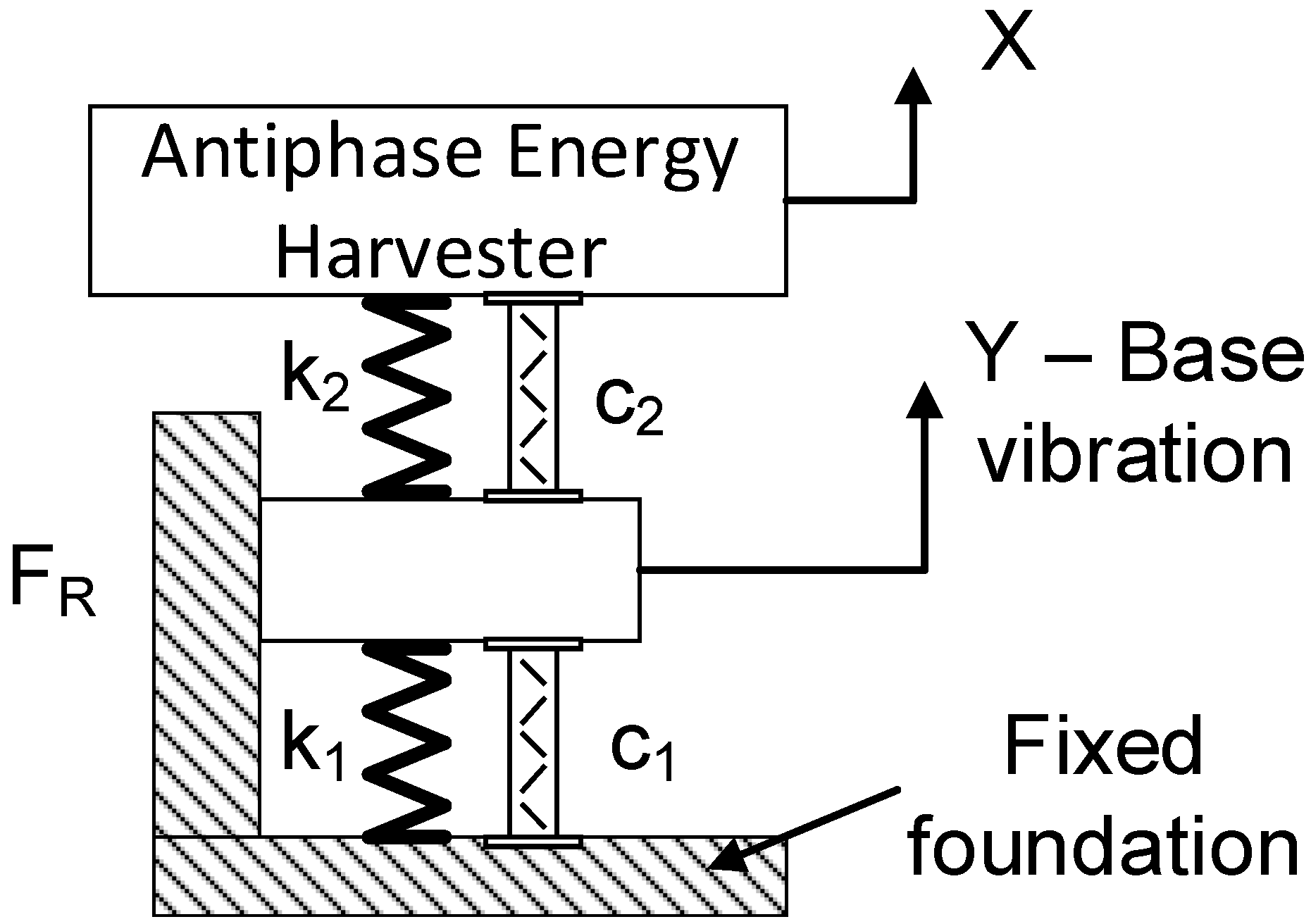
The working principle of the proposed rotation energy harvester is the utilization of rotation to generate a vibration through repulsive magnetic force, as shown in
Figure 1.
The overall design can be modelled as a two-degrees-of-freedom system (2-DOF) where k is the spring constant, c is the damper, and subscript 1 and 2 represent different systems. Y is the base vibration produced from the repulsive magnetic force. Due to the effect of the linear guiderail, the coulomb friction, denoted as F
R, is present in the system. The antiphase harvester is well explained in [
12].
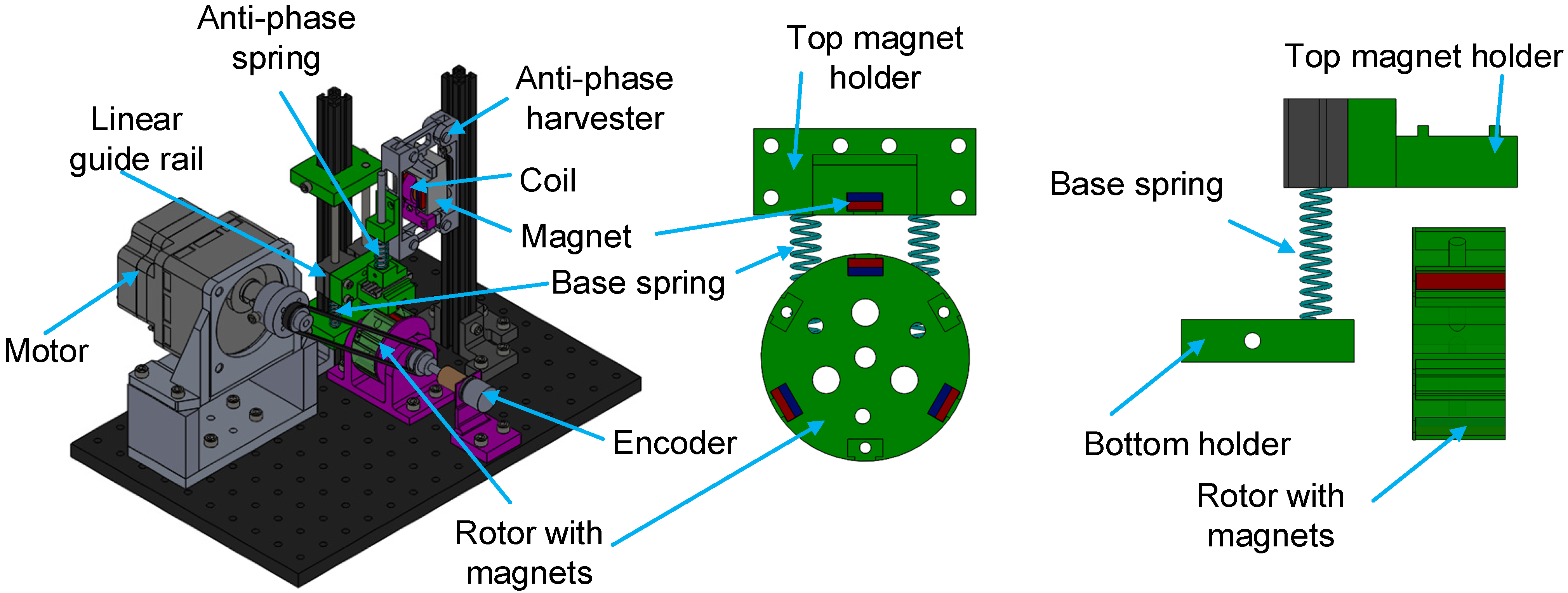
Figure 2 shows the 3D model of the proposed system.
Generally, the base vibration is produced from the repulsive magnetic force that is present in the rotor. There are three NdFeB permanent magnets (25 mm × 10 mm × 5 mm) on the rotor, and another magnet of same type is attached to the upper holder (where the holder is secured to the linear guiderail) to produce a vertical movement. The anti-phase energy harvester is also connected to the linear guiderail. There are two springs in the system, i.e., the base springs (two springs in parallel, as shown in
Figure 2 (right)) and an anti-phase spring. The springs are connected to the holder with a tight connection. The motor is used to produce a rotation that mimics the behavior of the real system, and it is connected to the rotor through the same pulley dimensions.
3. Experiment Setup
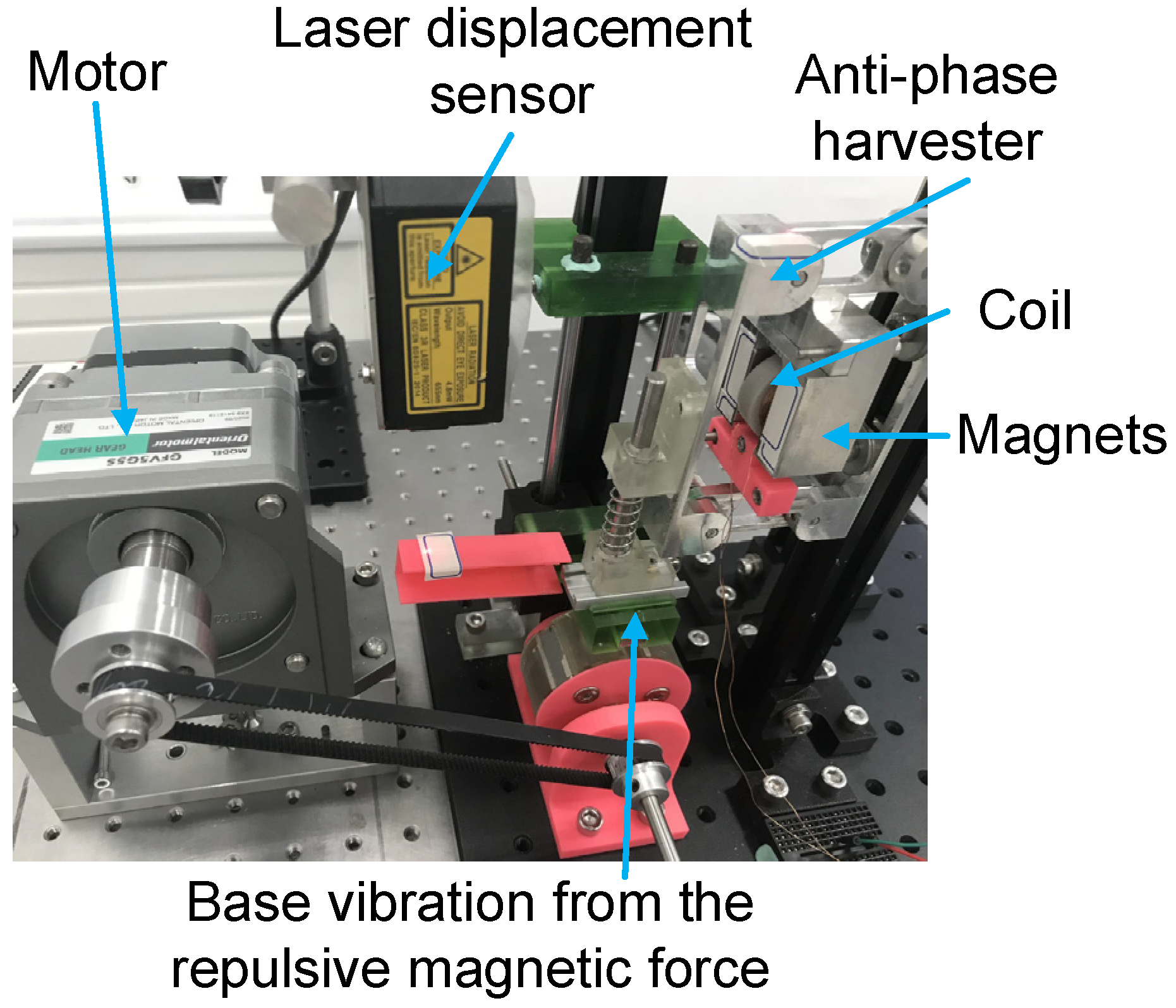
An electromagnetic vibration energy harvester prototype, based on the proposed concept of rotational energy harvesting, is designed through CAD software and manufactured using 3D printing and aluminum components.
Figure 3 shows the experimental setup.
The working principle of the proposed concept is explained in
Section 2. In this experiment, the different spring position sets on the prototype were studied to identify the best arrangement that harvests the maximum voltage. Four spring-position configurations were identified where the base and anti-phase springs were installed. The four different spring positions were D1—TBS (top bottom springs); D2—TS (top spring); D3—BS (bottom spring); and D4—NS (no spring). The top and bottom springs are referred to the antiphase and base springs, respectively. When the bottom springs were removed, there was a bottom holder to prevent collisions between the top magnet holder and the rotor with magnets. This bottom holder connected the base springs together. Although the springs were removed, the distances between the repulsive magnets were adjusted to the same values throughout the four configurations.
Figure 2 (right) shows that the springs were connected to the bottom holder.
The motor was operated at a speed from 200 rpm to 4000 rpm with a gear ratio of 5 at the interval speed of 50 rpm or 100 rpm. The experiments were repeated three times for accurate data. The energy harvester was connected to the external load resistance of 100 Ω. Two laser displacement sensors (LK-H050) captured the amplitude at base spring and the top of the anti-phase spring. An encoder was used to capture the rotation to make sure the vibration occurred at the correct location. All the data were connected to the NI data acquisition card (NI-USB 6210) and were processed in the LabVIEW.
4. Experimental Results
The data relating to the performance were collected during the experiment. The parameters utilized for the axis labels of plots were rotation frequency, voltage, and base and anti-phase amplitude.
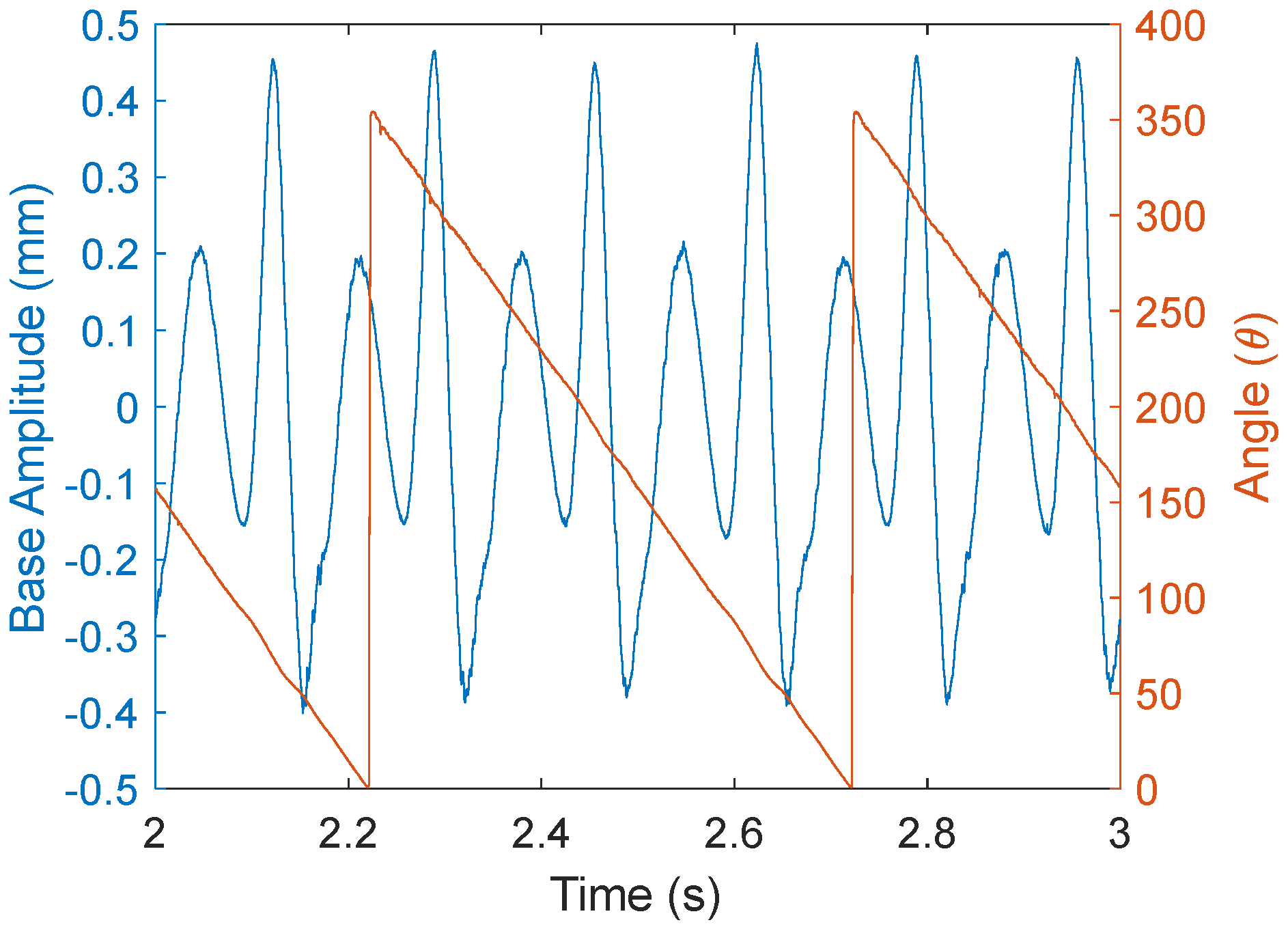
Figure 4 shows the time response in revolutions.
In one complete revolution, there were three base vibration amplitudes, as shown in
Figure 4. This was because, due to the fact that the rotor had three equally spaced permanent magnets, each repulsive magnet would be considered as a non-linear spring, which would cause the repulsive vibration. Hence, peaks of around ±0.4 mm amplitude were observed. After the first magnet repelled the top magnet holder, the holder would reach the maximum amplitude of +0.45 mm while the rotor rotated where the magnetic repulsive force was at its minimum before the second magnet exerted the repulsive force again. Thus, the top magnet holder would drop to the lowest amplitude of −0.4 mm. In addition, the rotation was in a steady-state condition; the springs’ energy would be rebounded to another small amplitude of +0.2 mm/−0.15 mm.
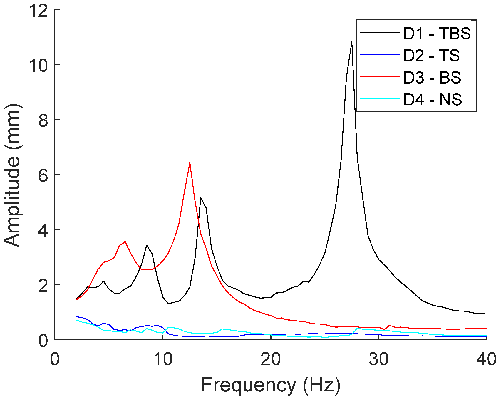
Figure 5 shows the graph of the absolute displacement difference of the base for four different designs.
D1—TBS demonstrated three clear peaks, which referred to the resonance frequency of the system when considering the base amplitude. The first peak happened at 8.5 Hz, where the amplitude was 3.44 mm; the second peak was located at 13.5 Hz, where the amplitude was 5.16 mm; and the last peak was at 27.5 Hz, where the amplitude was 10.83 mm. With the increasing of the rotation speed, the amplitude dropped back to about 2 mm after the peak. This was because of the magnetic repulsive force. The force was enough to move the top magnet holder to an amplitude of about 2 mm, except near the resonance of the spring. The 2 mm amplitude would become smaller if the weight on top of the magnet holder was heavier. From the vibration theory, it could be deduced that the spring would amplify the response when the frequency ratio was smaller than
. Hence, the presence of the peaks recorded in
Figure 5 could be deduced. The first and second peaks were the springs that were connected to the base holder. In fact, these two springs were not sufficiently tight as the springs were placed into the holder without the use of adhesive bonds. The springs may have moved slightly and changed the spring constant; hence, there were two resonances. The third peak was from the anti-phase spring.
D3—BS shows two peaks at smaller frequencies. The first peak happened at 6.5 Hz, where the amplitude was 3.56 mm. The second peak was at 12.5 Hz, where the amplitude reached 6.43 mm. In addition, it was clear that both the anti-phase spring and the no-spring design yielded very little maximum base displacement difference for all frequency ranges, and identification of the peak was unclear, especially for frequencies over 10 Hz. To conclude, D1 and D3 could generate relatively obvious resonance when considering the base vibration. Besides, the performance of bottom spring configuration was better than both spring configurations at low-frequency ranges, i.e., 0–13 Hz.
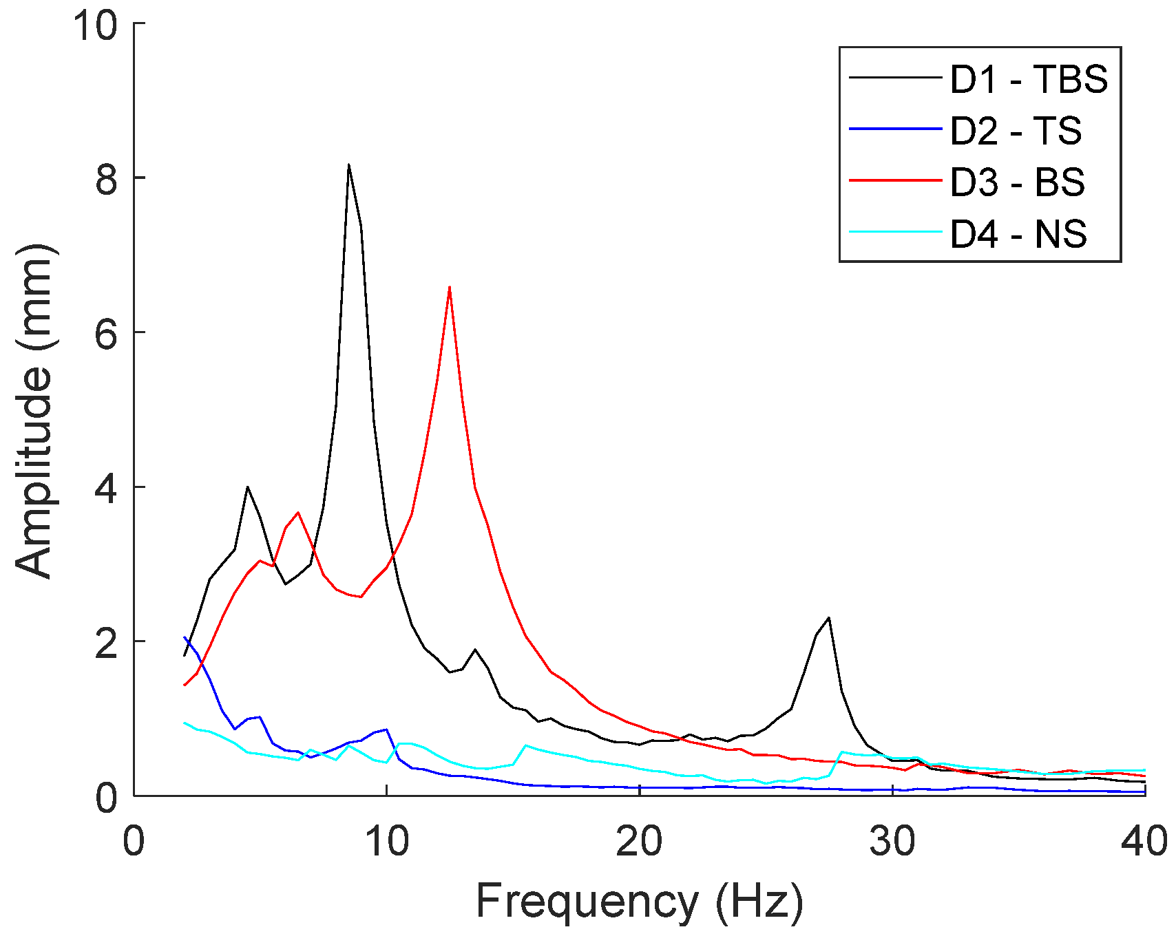
When considering the absolute amplitude during the antiphase on the basis of the data represented in
Figure 6, the conclusions could differ partially as compared with the previous scenario. The overall trend demonstrated that the magnitudes of the antiphase-displacement difference for all configurations were descending with the increasing of the rotational speed. The displacement was also affected by the base amplitude. Specifically, D1—TBS also created three peaks, but the location and the magnitude changed. The first peak was located at 4.5 Hz, with an amplitude of 4 mm; the second peak, which was the largest one, was located at a rotation frequency of 8.5 Hz with an amplitude of 8.17 mm; and the last peak occurred at 27.5 Hz with a displacement difference of 2.31 mm. This was due to the effect of the friction, which was responsible for the smoothness of the movement of the linear guiderail and the harvester. In addition, the number of the peaks was also two for D3—BS. The first peak was at 6.5 Hz, and the amplitude was 3.67 mm; the second peak was at 12.5 Hz, and the amplitude was 6.58 mm. Finally, both D2 and D4 did not provide a plain peak for the analysis. Hence, these were not considered in the design as the voltage was related to the antiphase amplitude. A brief observation can be made, namely that the resonance performance of D1 was generally better than other designs when the frequency was lower than 10 Hz and larger than 21.5 Hz. D3 showed better performance when the frequency was between 10 and 21.5 Hz.
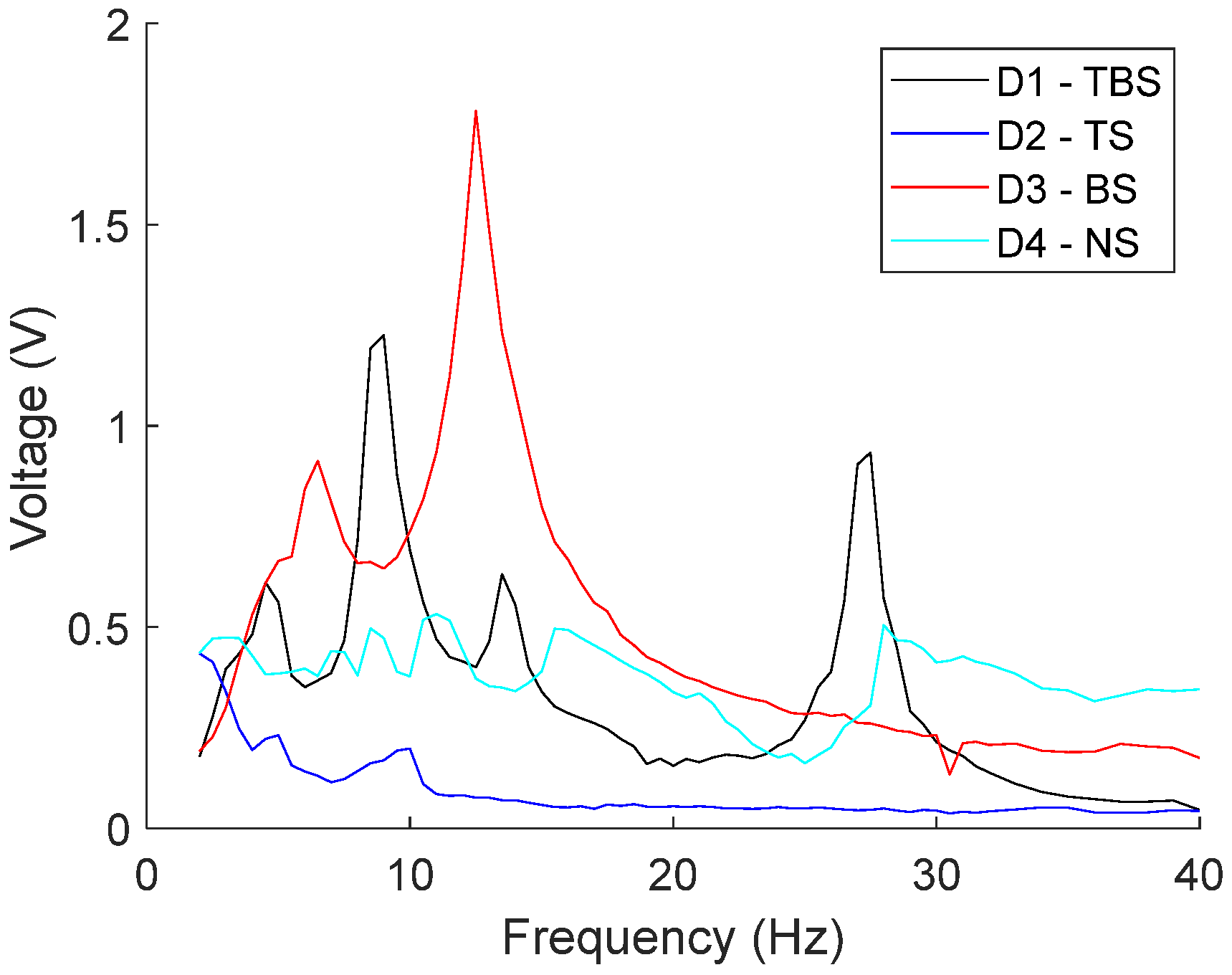
Figure 7 demonstrates the voltage generated by the vibration energy harvester for different frequency and design configurations. The voltage could be an intuitive reflection of the energy harvester’s performance. The general observation can be made that the no-spring configuration could generate about 0.5 V of electricity on average, but a drop could be noticed when the frequency reached 25 Hz. However, the top spring did not contribute to the enlargement of electricity generation for all frequencies; this was because the voltages for all frequencies were smaller than those observed for the no-spring configuration. In contrast, the utilization of the bottom spring could significantly magnify the voltage for a certain frequency range. The maximum voltage could reach 1.78 V at the frequency of 12.5 Hz. If the values obtained for both the top and bottom springs are added together, the trend of the curve is similar to the overlap of both single spring conditions.
5. Conclusions
In conclusion, the addition of the bottom spring was found to have a significant effect on the amplitude and voltage amplification, but it was also apparent that the top spring could contribute inversely and impact the performance to some extent. However, the findings suggest that the combination of the top and bottom springs can lead to better performance at a certain frequency range. Thus, if the vibration source frequency is known, the design can be changed based on the condition, but this is always a challenge when taking into account friction for random and non-linear vibrations.
In this paper, conceptual designs, using an anti-phase energy harvester, were proposed. The experiment can be improved with the use of multiple materials that have better magnetic flux for the design of the rotational part, so that the repulsive force can be maximized. In addition, the proposed concept designs are useful for low rotation frequencies and can enable the provision of voltage to wireless sensor nodes. The energy conversion and storage, and the optimization of the design, will be considered in future works.
Author Contributions
Conceptualization, C.K.T.; methodology, X.W.; software, W.H; validation, C.K.T.; formal analysis, W.H.; investigation, X.W. and J.X.; resources, C.K.T.; writing—original draft preparation, X.W., W.H., J.X. and C.K.T.; writing—review and editing, C.K.T.; visualization, X.W.; Supervision, C.K.T. All authors have read and agreed to the published version of the manuscript.
Funding
This research received no external funding.
Institutional Review Board Statement
Not applicable.
Informed Consent Statement
Not applicable.
Data Availability Statement
Not applicable.
Conflicts of Interest
The authors declare no conflict of interest.
References
- Wang, Z.; He, L.; Zhang, Z.; Zhou, Z.; Zhou, J.; Cheng, G. Research on a Piezoelectric Energy Harvester with Rotating Magnetic Excitation. J. Electron. Mater. 2021, 50, 3228–3240. [Google Scholar] [CrossRef]
- Zhou, Z.; Qin, W.; Du, W.; Zhu, P.; Liu, Q. Improving energy harvesting from random excitation by nonlinear flexible bi-stable energy harvester with a variable potential energy function. Mech. Syst. Signal Process. 2019, 115, 162–172. [Google Scholar] [CrossRef]
- Foong, F.M.; Thein, C.K.; Yurchenko, D. Structural optimisation through material selections for multi-cantilevered vibration electromagnetic energy harvesters. Mech. Syst. Signal Process. 2022, 162, 108044. [Google Scholar] [CrossRef]
- Fan, K.; Liu, J.; Wei, D.; Zhang, D.; Zhang, Y.; Tao, K. A cantilever-plucked and vibration-driven rotational energy harvester with high electric outputs. Energy Convers. Manag. 2021, 244, 114504. [Google Scholar] [CrossRef]
- Liu, H.; Fu, H.; Sun, L.; Lee, C.; Yeatman, E.M. Hybrid energy harvesting technology: From materials, structural design, system integration to applications. Renew. Sustain. Energy Rev. 2021, 137, 110473. [Google Scholar] [CrossRef]
- Li, X.; Bi, C.; Li, Z.; Liu, B.; Wang, T.; Zhang, S. A Piezoelectric and Electromagnetic Hybrid Galloping Energy Harvester with the Magnet Embedded in the Bluff Body. Micromachines 2021, 12, 626. [Google Scholar] [CrossRef] [PubMed]
- Yang, Y.; Pian, Y.; Liu, Q. Design of energy harvester using rotating motion rectifier and its application on bicycle. Energy 2019, 179, 222–231. [Google Scholar] [CrossRef]
- Fan, K.; Cai, M.; Wang, F.; Tang, L.; Liang, J.; Wue, Y.; Qua, H.; Tan, Q. A string-suspended and driven rotor for efficient ultra-low frequency mechanical energy harvesting. Energy Convers. Manag. 2019, 198, 111820. [Google Scholar] [CrossRef]
- Tan, Q.; Fan, K.; Guo, J.; Wen, T.; Gao, L.; Zhou, S. A cantilever-driven rotor for efficient vibration energy harvesting. Energy 2021, 235, 121326. [Google Scholar] [CrossRef]
- Nezami, S.; Jung, H.; Lee, S. Design of a disk-swing driven piezoelectric energy harvester for slow rotary system application. Smart Mater. Struct. 2019, 28, 074001. [Google Scholar] [CrossRef]
- Zou, H.-X.; Zhang, W.; Li, W.-B.; Wei, K.-X.; Gao, Q.-H.; Peng, Z.-K.; Meng, G. Design and experimental investigation of a magnetically coupled vibration energy harvester using two inverted piezoelectric cantilever beams for rotational motion. Energy Convers. Manag. 2017, 148, 1391–1398. [Google Scholar] [CrossRef]
- Foong, F.M.; Thein, C.K.; Yurchenko, D. A novel high-power density, low-frequency electromagnetic vibration energy harvester based on anti-phase motion. Energy Convers. Manag. 2021, 238, 114175. [Google Scholar] [CrossRef]
| Publisher’s Note: MDPI stays neutral with regard to jurisdictional claims in published maps and institutional affiliations. |
© 2021 by the authors. Licensee MDPI, Basel, Switzerland. This article is an open access article distributed under the terms and conditions of the Creative Commons Attribution (CC BY) license (https://creativecommons.org/licenses/by/4.0/).


