1. Introduction
Vibration energy harvesting (VEH) has emerged as one of the most promising sources of sustainable energy to power low-powered electronics [
1] and structural health monitoring. However, studies that involve powering larger devices have also been carried out [
2]. Among the different approaches to convert mechanical vibrations into electricity, the two most commonly applied methods are piezoelectric transducers and electromagnetic induction. While piezoelectric VEH generally dominates in the micro-volume scale, electromagnetic VEH tends to perform better at larger volumes [
3,
4].
Over the past decade, many researchers have proposed different methods to optimize the performance of a VEH device. One of the most well-known conclusions is that using a triangular cantilever beam increases the performance of a piezoelectric VEH [
5,
6,
7]. This is because the power output of a piezoelectric VEH mainly relies on the stress induced in piezoelectric materials. A deformed triangular cantilever beam exhibits a larger and more uniform stress along the length of the beam as compared to a regular rectangular beam [
8]. Nevertheless, the benefits of a triangular cantilever beam for an electromagnetic VEH have not yet been explored.
In this study, the use of a triangular cantilever beam for electromagnetic VEH applications was evaluated by analyzing its material damping as compared to a rectangular cantilever beam. Both beams were modeled in finite element software, and the material damping of both beams for different beam dimensions were determined using the critically damped stress method. The amplitude responses of both beams were then evaluated for a certain coil component under a set of constraints, and the benefits of the triangular beam for electromagnetic VEH applications were highlighted.
2. Power and Damping of a Cantilevered Electromagnetic VEH
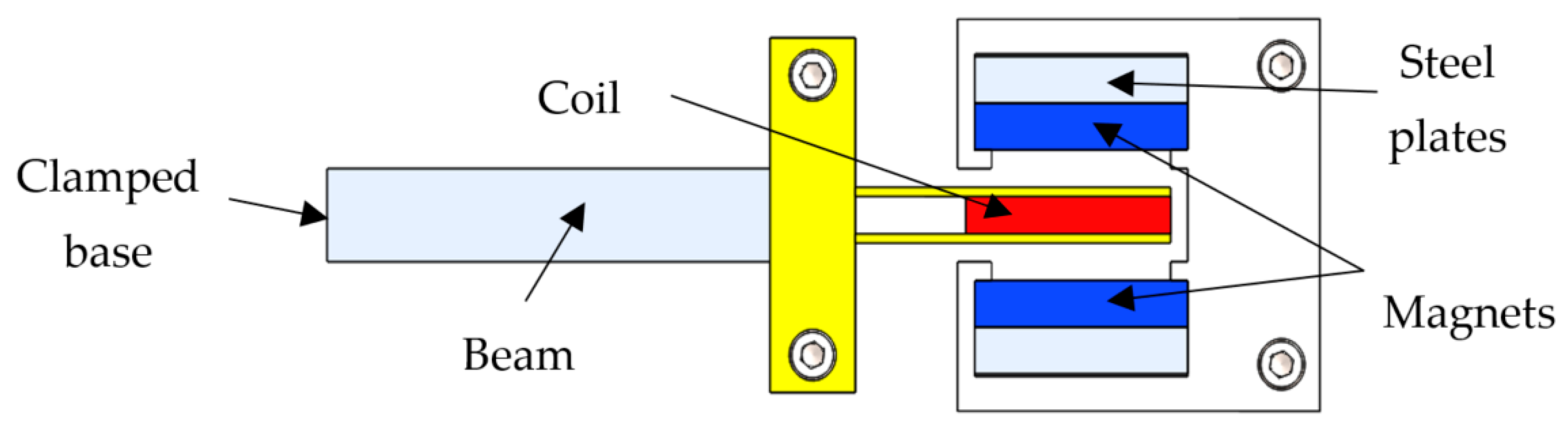
Figure 1 illustrates an example of a typical cantilevered electromagnetic VEH device. The base of the cantilever beam is clamped to a vibrating structure, whereas a coil component is clamped to the free end of the beam and placed within a magnetic field generated by several permanent magnets. Based on Faraday’s law of electromagnetism, voltage is induced in the coil when the coil vibrates in the magnetic field. This voltage is maximized at a resonance where the frequency of the input vibration is equal to the natural frequency of the harvester.
The damping of an electromagnetic VEH device is generally the sum of its structural damping and its electromagnetic damping components. Under the optimum load resistance condition, electromagnetic damping becomes approximately equal to structural damping [
9]. Assuming a harmonic input vibration and a constant magnetic field, the maximum average power output induced by the harvester at the first vibration mode resonance can be written as [
8]:
where
P is the output power, m is the effective mass of the harvester,
G is the acceleration of the input vibration,
is the harvester’s fundamental natural frequency and
is the first-mode structural damping. Equation (1) shows that the power output is dependent on several parameters. However, if the same coil and magnet components were used and the input vibration and natural frequency of the harvester were maintained, the structural damping becomes the main contributor towards its power output.
The structural damping of a harvester can be further broken down into several discrete damping components, which include material damping, thermoelastic damping, viscous air damping and support damping [
10]. The sum of all these damping components makes up the total structural damping of the harvester. However, for macro-sized structures, only material damping and thermoelastic damping make a significant contribution to the overall structural damping [
11]. Nevertheless, for some materials, such as stainless steel, thermoelastic damping is approximately 25 times lower than material damping in macro-sized structures. Hence, Equation (1) can be approximated as
where
is the material damping of the harvester. For a cantilevered harvester, material damping originates from the molecular interactions inside the material of the cantilever beam. However, very few methods are available to predict this damping.
Recently, a new method to evaluate material damping of cantilever beams was proposed by Foong et al. [
11]. This method relates the material damping ratio of the cantilever beams to twice its maximum resonant stress under the critically damped condition when the damping ratio is equal to one, otherwise defined as the critically damped stress. Hence, it was dubbed as the critically damped stress method. The main advantage of this method is that only two iterations are required to determine the material damping of cantilever beams, making it very practical for finite element applications. For a stainless-steel material, the material damping ratio can be related to the critically damped stress,
, by the following expression [
12]:
The equation has a mean error of approximately 10.0% and can be used to predict the material damping of stainless-steel cantilever beams with sufficient accuracy. Additionally, it has been shown in [
12] that the same equation is also capable of predicting other cantilevered structures aside from a uniform rectangular beam.
3. Finite Element Modeling and Methodology
In this study, the performance of a stainless-steel triangular cantilever beam for electromagnetic VEH applications was analyzed through finite element analysis (FEA) by studying material damping. The results of the triangular beam were then compared to the results of a regular uniform rectangular cantilever beam. The reason this method was chosen was because it is analytically difficult to accurately model the vibration response of a triangular cantilever beam. Both beams were modeled in ANSYS software using tetrahedral elements and meshed using a size of 0.5 mm. The properties of a stainless-steel material were assigned and two identical proof masses weighing 19.0 g each were added at the free end of each beam, as seen in
Figure 2. Initially, the thickness and the width of the beam were fixed at 1.0 mm and 5.0 mm, and the length of the beams were adjusted to acquire the same fundamental natural frequency of ω_1 = 32.34 Hz. This also inevitably changed the volume of the cantilever beam.
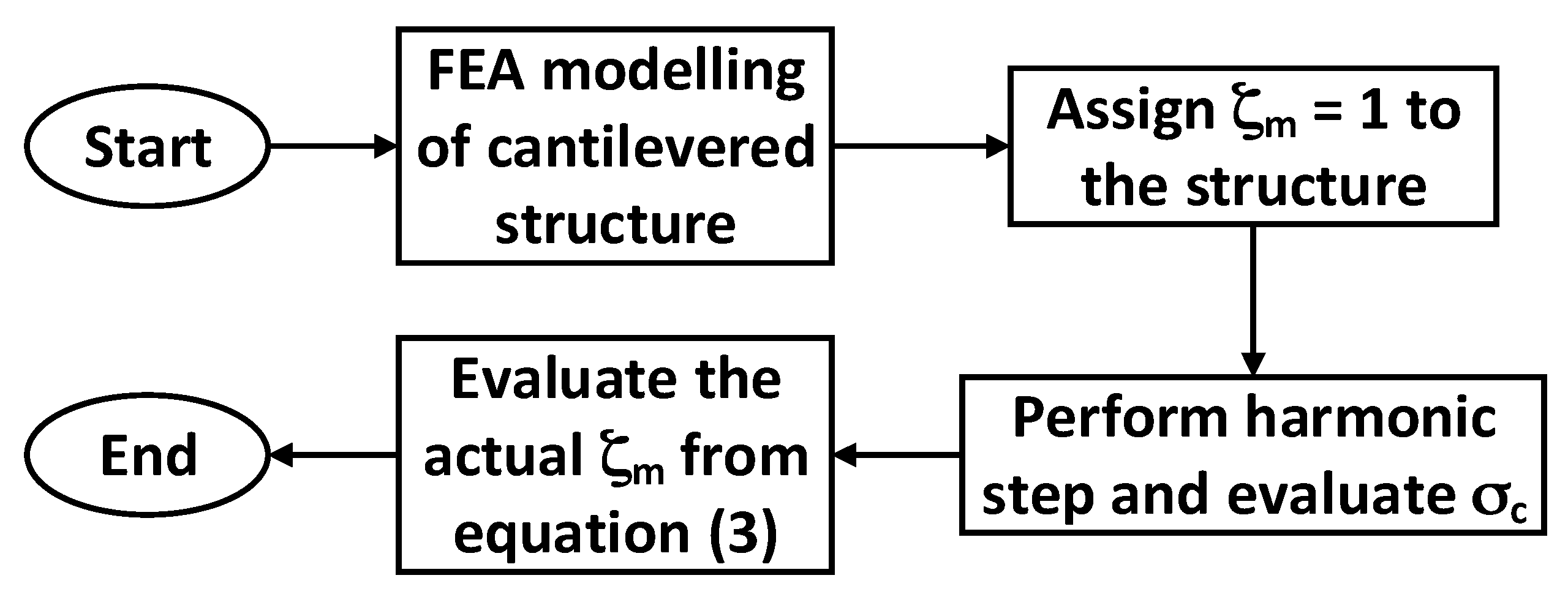
A fixed constraint was applied to the base of the beam to simulate a clamped condition, and a constant base acceleration of G = 1.96 ms
−2 was used in the simulation. Material damping for each beam was then obtained using the flowchart shown in
Figure 3.
The analysis was then repeated several times by changing the width of both beams in increments of 1.0 mm up to a width of 10.0 mm. For each change in width, the length of the beams was adjusted to meet the same natural frequency and material damping was recorded. The same base acceleration input was used in all analysis.
4. Results and Discussion
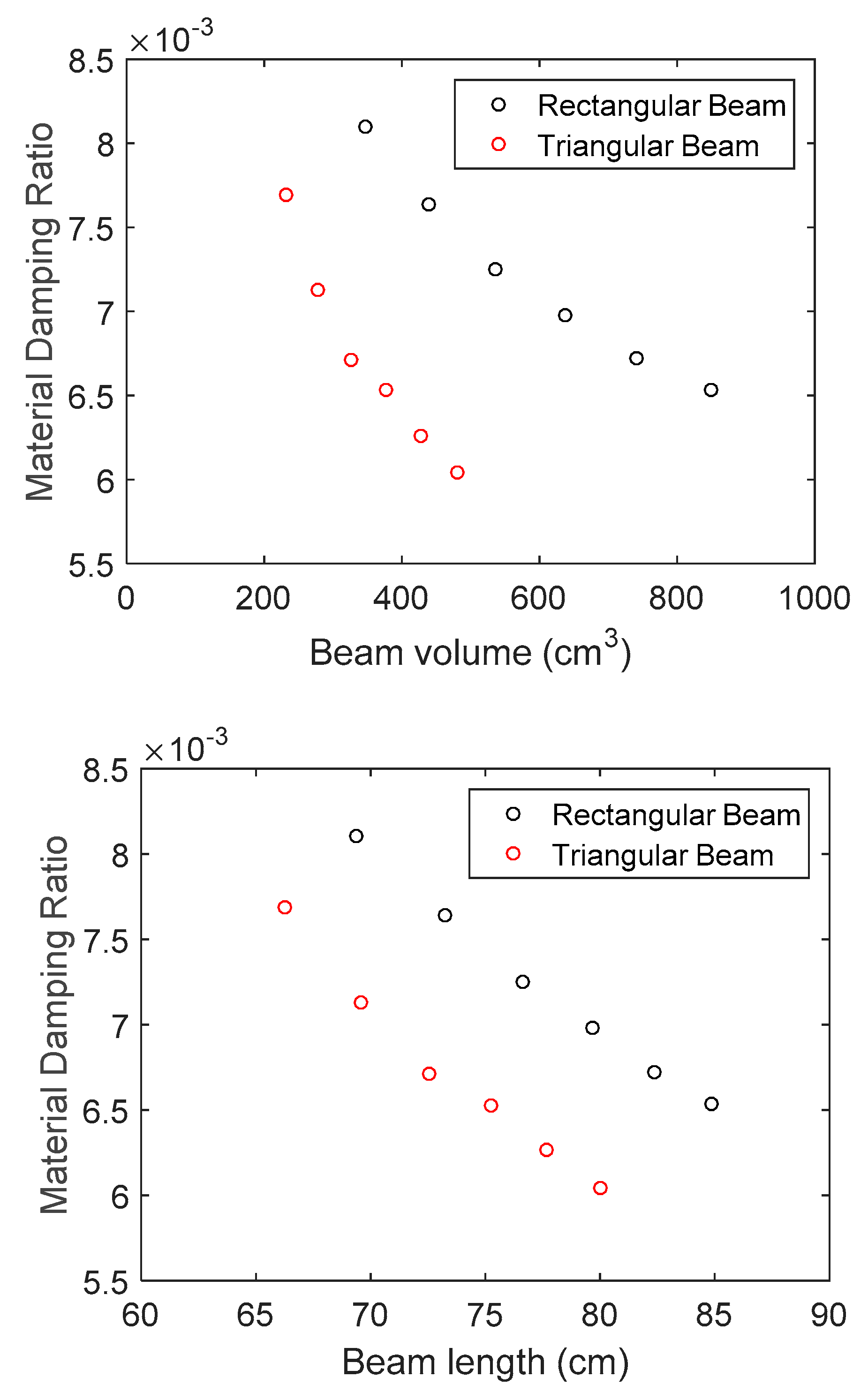
Figure 4 shows the variation in material damping against the beam volume and the beam length for the triangular and the rectangular cantilever beam.
Figure 4 shows that for both beams, material damping generally decreases with beam volume and beam length due to the reduction in stress at larger volumes. However, under the same volume or length, the triangular cantilever beam exhibits a lower material damping than the rectangular beam, which, according to Equation (2), would result in a larger power output. On average, the triangular beam recorded 7.1% lower damping than the rectangular beam. The analysis was then repeated for the following design in
Figure 5, where a coil component, which was modeled based on the real item, was attached to the beam instead of the proof mass. This component weighed approximately 21.13 g.
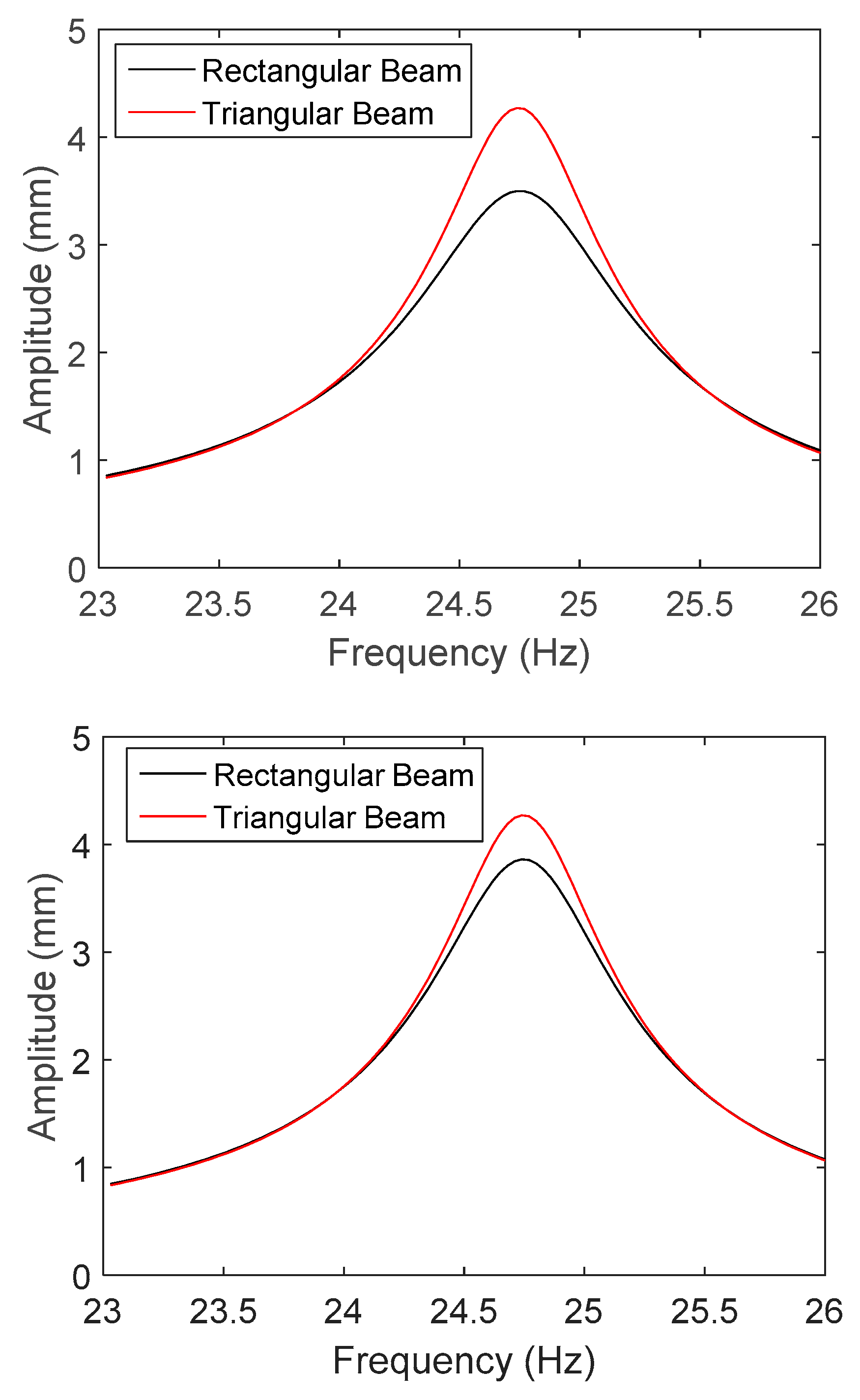
This analysis was conducted so that the results here can be verified experimentally in future works. This time, two scenarios were considered. In the first scenario, the volume of the beam was constrained to 480 cm
3, whereas in the second scenario, the length of the beam was constrained to 80.0 mm. In both scenarios, the natural frequencies of both beams were tuned to 24.75 Hz and the same base acceleration of G = 1.96 ms
−2 was applied. The condition of optimum load resistance (electrical damping = structural damping ≈ material damping) was assumed in the analysis. The amplitude responses of the two beams under the two mentioned scenarios are compared in
Figure 6.
The maximum average power output at resonance for each beam in both scenarios was then estimated using the following equation:
where
is the amplitude of the harvester at the fundamental resonance mode. Note that Equation (4) is simply Equation (1) expressed in terms of the resonance amplitude. For the first scenario, a maximum average power output of 13.8 mW was obtained for the triangular beam and an output of 11.3 mW was obtained for the rectangular beam, implying a 22.1% higher power output for the triangular beam. For the second scenario, the triangular beam and the rectangular beam recorded a maximum power output of 13.8 mW and 12.4 mW, respectively, showing an 11.3% increase for the triangular beam. Therefore, this proves that a triangular cantilever beam is also beneficial for electromagnetic VEH applications.
5. Conclusions
In this study, the application of a triangular cantilever beam in electromagnetic VEH applications was analyzed by comparing the structure’s material damping to that of a uniform rectangular cantilever beam. It was found that under the optimum load resistance condition, the maximum average power output of an electromagnetic harvester is mainly dependent on its material damping. A triangular and a rectangular cantilever beam was then modeled in finite element software, and the corresponding material damping was predicted using the critically damped stress method. Upon comparison, the triangular beam displayed an average of 7.1% lower material damping than the rectangular beam. Further analysis demonstrated that the power output of the triangular beam was 21.7% higher than the rectangular beam for the case of a constrained beam volume, and 11.3% higher if the beam length was fixed instead. Hence, this highlights the benefits of a triangular cantilever beam for electromagnetic VEH. An experiment will be conducted as part of future works to validate the analysis conducted in this work. In addition, the work presented here will definitely be beneficial to the self-powered sensor in the future, especially in predicting the power through different designs.


