Abstract
A lot of novel surface treatment technologies have appeared over the last few decades, offering great possibilities for practical use. Modified surfaces have confirmed their successful application in thermal engineering for boiling heat transfer enhancement and single-phase convection. Several classification approaches for boiling surfaces exist in the literature; however, a full, physically based, and commonly accepted universal system is still missing. This paper proposes such a classification system, based on considerations of physical mechanisms underlying the nucleation process and enhancement mechanism during different stages of vapor bubble growth. It also presents an overview of recent advances in the development of enhanced boiling surfaces.
1. Introduction
The boiling of liquids certainly determines the trends in numerous processes of heat and mass transfer technology. As an example, one can refer to the processes of energy exchange in steam power plants and the thermal decomposition of liquid mixtures. Accordingly, there have not been enough efforts in the past to investigate the objective laws of boiling. Meanwhile, some model ideas have been developed, and corresponding correlations for the heat transfer of boiling liquids have been derived. Although these correlations provide satisfactory answers to several technical questions, only a few very first attempts have been undertaken to understand the phenomenon of boiling itself—even the boiling of pure substances on technically smooth heating surfaces. The reason for this is the multi-layered nature of phase exchange, extending from the creation of a viable nucleus in the metastable initial phase, through the phase growth, to the hydrodynamics of the heterogeneous fluid system with the moving phase interface.
The relations become significantly more complex if the heating surface is provided with a structure to intensify the boiling kinetics. The structure should reduce the driving temperature difference, which is primarily achieved by enlarging the nucleation site density. Originally, structures were generated by the mechanical machining of the heat transfer surface. Numerous forms of micro-fins and cavities in the heating surface are created in such a manner that, besides enhancing nucleation site density, also increases the bubble detachment frequency. Re-entrant cavities with different dimensions have been generated and successfully tested in recent years. Next generations of microstructures have been developed, spanning from the emery paper treatment and sandblasting of the heating surface to thermally generated porous layers (sintered or plasma-sprayed) and the implementation of ions through the bombardment of the surface by high-energy particles. The disadvantages of such surfaces and the processes used for their creation are often related to economic grounds. Furthermore, together with a tendency to dry out at low heat fluxes (especially in the case of multi-layer structures), structured surfaces can demonstrate the unexpectedly strong deterioration of boiling.
The main requirements for an enhanced boiling surface can be formulated as follows [1,2,3,4,5,6,7,8]:
- –
- High heat transfer coefficient compared with technically smooth surfaces;
- –
- Low boiling inception superheat;
- –
- High critical heat flux (CHF);
- –
- Independence of the surface superheat from the heat flux;
- –
- Long-time performance stability;
- –
- Weak fouling.
All these features are seldom met simultaneously on a single surface. Therefore, their development is still an important task. Novel surface modification techniques, at the same time, require some universal ordering, which would provide a better understanding of the physical background for the enhancement of existing surfaces on the one hand, and, on the other hand, would be flexible enough to enable future improvements. To propose a universal classification system of surfaces in boiling applications, one has to understand the mechanisms affecting nucleation. Although extensively studied, the mechanisms associated with bubble nucleation remain poorly understood, with many questions still open.
The present paper is organized in the following way. First, the overview of the physical processes underlying the boiling phenomenon is given. Next, the classification system for enhanced boiling surfaces is introduced, and the results of the investigations into novel microstructured surfaces are presented. This paper is completed with conclusions.
2. Physical Fundamentals of Boiling at Solid Surface
2.1. Initial Nucleation
The very first stage of a vapor bubble’s life is the formation of a bubble nucleus. It is commonly accepted that the first nuclei are created in the liquid as it begins to boil, due to fluctuations in liquid density. Like any fluctuation process, the initial nucleation is characterized by probability. The minimal diameter of a spherical nucleus that can form a viable bubble in the bulk liquid is given by Equation (1) (see, for example, Labuntsov [9]):
where f [J/kg] represents the specific Gibbs energy for vapor (denoted with subscript V) and liquid (denoted with subscript L), ρ [kg/m3] stands for density, σ [N/m] is the surface tension, and dcr [m] denotes the diameter of the critical (viable) vapor bubble.
When a nucleus is created near a surface, the surface energy must be taken into account. The energy barrier to be surmounted by a fluctuation is given by Labuntsov [9] as follows:
where ΔΦ [J] is the nucleus energy barrier, S [m2] is the surface area between liquid and vapor, SW [m2] is the surface area between vapor and the wall, and θ [°] is the contact angle.
Equation (2) introduces the concept of a wetting (contact) angle. It immediately divides all surfaces into two groups with different wetting properties: hydrophobic and hydrophilic surfaces, which have lower or higher values of the energy barrier (2) correspondingly. These values are always lower in comparison with the nucleation inside the liquid far from the surface:
Therefore, one may expect lower inception superheats required for the nucleation on hydrophobic surfaces, which has been confirmed by numerous experiments; see Labuntsov [9]. Another way to decrease the energy barrier (2) is to provide a larger contact area between the nucleus and the wall (larger values of SW in Equation (2)). This leads to the suggestion that rough surfaces must result in lower inception superheats, another fact widely confirmed by experiments.
One must distinguish the difference between the local contact angle θ, appearing in Equation (2), and the average contact angle, observed visually in experiments. A local contact angle is the result of the energetic interaction of the molecules of liquid, solid and vapor and it is a physicochemical property of the system. The apparent contact angle θ0 is a more complex property, which also accounts for the microstructure of the surface according to
Equation (4) is known as the Wenzel expression [10]; its thermodynamic bases were provided by Derjagin [11].
The quantity ξ is the ratio of the projected surface area to the actual (wetted) surface area, and it is the reverse of the roughness coefficient. As long as ξ ≤ 1 for all real surfaces, θ > θ0 for θ < π/2 and θ < θ0 for θ > π/2. At present, the local contact angle remains unknown, while the apparent contact angle is poorly studied.
The contact angle has a sense only when a linear scale of the process under consideration is given. For very small scales, which include a nucleus, the Young–Neumann law, used in the development of Equation (2), must be modified to add the line tension appearing in the system. As was shown by Derjagin et al. [12], the profile of a liquid layer between a solid surface and vapor in an equilibrium state is not unique for a given disjoining pressure. Figure 1 illustrates the possibility of two different interface profiles (1 and 2) and the disjoining pressure isotherm.
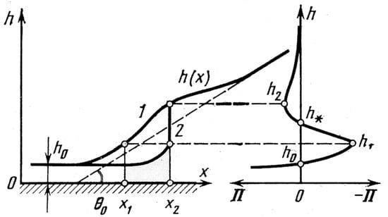
Figure 1.
Possible interface profile h (x), 1 and 2, for a given disjoining pressure isotherm Π (on the right). Reproduced with permission from [12]; published by Nauka, 1987.
Although the very first stages of bubble life are still hidden, an important conclusion from Equations (1)–(4) is that only the surface cavities with a size of about d, deduced directly from Equation (2), can affect the initial nucleation. For larger cavities, the energy barrier given by Equation (2) achieves values equal to bulk liquid.
For different liquids and pressures, Equation (1) gives the critical vapor bubble radii in the range of 10−6 m to 10−5 m. Therefore, cavities of such sizes are preferable for initial nucleation in general. The experimental validation of this result can be found in the literature, for example, by Nelson [13] and Luke et al. [14]. Figure 2 illustrates the number of surface cavities available for nucleation dependent on their sizes.
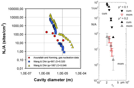
Figure 2.
Active nucleation sites density dependent on the cavity size. (Left)—water and gas nucleation data; see ref. [13]. Reproduced with permission from [13]; published by: Elsevier Inc. (Amsterdam, The Netherlands), 2001. (Right)—boiling of propane on a copper sandblasted tube; see ref. [14]. Reproduced from Luke, A.; Danger, E.; Gorenflo, D. Size distribution of active and potential nucleation sites in pool boiling. In Proceedings of the 12th IHTC 2002; 3:383-388. Copyright © 2002 Elsevier Masson SAS. All rights reserved.
Modified surfaces obtained with plasma or flame sprayed/baked particles have a great number of cavities with a wide range of sizes, providing low inception superheats and high heat transfer coefficients. A novel microstructure, developed by Mitrovic et al. [4,5,6,7,8,15], allows obtaining even smaller cavities.
2.2. Growing Vapor Bubble
After the boiling inception, the further capability of a surface to produce vapor bubbles is determined by its number of nucleation sites. Enhanced surfaces offer a greater number of nucleation sites in comparison with a technically smooth surface, subsequently having higher heat transfer coefficients. A developed microgeometry of an enhanced surface acts as a vapor trapper as well, allowing bubbles to be generated from the vapor rests inside the structure. However, within thicker structures, complex vapor–liquid counterflows develop, thereby decreasing the performance (especially at high heat fluxes) and the critical heat flux significantly.
It is known that evaporation into the growing vapor bubble occurs mainly at its bottom in the Three-Phase Line (TPL) region, projected as point A in Figure 3. Evaporation at the TPL depends strongly on the conditions of the surface; see Mitrovic [4] and Labuntsov [16].
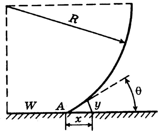
Figure 3.
On the determination of the local heat flux; see ref. [16].
One of the first works that introduced the concept of the micro-layer underlying a growing vapor bubble was published by Labutsov [15]. It suggested that the local heat flux, being received by a single vapor bubble, could be estimated as follows:
where the distance from the wall is given by the following:
In Equation (6), the quantity yA denotes the minimal thickness of a liquid layer near the TPL, where Equation (5) still has sense and θ0 is the average contact angle. Labuntsov [15] further suggested that the order of magnitude of yA must be about the value of intermolecular distances in a liquid, i.e., yA = (10−7 to 10−8) cm.
Physically, this means that there is always a fluid layer under a growing vapor bubble, which is unable to evaporate. The potential of the energy field, created by the surface forces, must be high enough to lock the fluid molecules in this layer. It seems that the adsorption properties of the surface play a major role in this case as well as the microstructure of the surface with the characteristic linear scale of about 1 nm. Some modern technologies considered below in the article allow creation of surface layers with a thickness of several nanometers as reported by Upot et al. [17]. Such surfaces seem to have a great influence on the mechanisms occurring along the TPL and in the micro-layer.
As shown by Mitrovic [4], a longer TPL allows for higher evaporation rates and subsequently higher heat transfer coefficients. The ideal would be to have a TPL with an infinite length. For a bubble on a plain surface, the TPL length is limited, while for modified surfaces with micro-pins described by Mitrovic et al. [4,5,6,15], the TPL length depends upon the number of structural elements (pins) per unit of area—for a bubble with a 1 cm2 contact area, it can be up to 6 m.
A large number of vapor bubbles cool down the surface effectively, generating a noticeable and almost instantaneous temperature gradient, which depends on the wall’s material properties and the applied heat flux. For example, Auracher et al. [18] and Judd et al. [19] report the surface spatial gradients to be from 2 K/mm for copper to 10 K/mm for stainless steel (measured already at moderate heat fluxes).
Considering the saturated nucleate boiling, one must not neglect the simultaneous condensation of a growing vapor bubble at the interface contacting the liquid; see Kuzma-Kichta et al. [20]. It was shown that in the case of saturated water boiling, the condensation can consume up to 25% of the applied heat flux. The simultaneous evaporation and condensation of a single growing vapor bubble cause a complex temperature field on the solid surface and determine the work of active nucleation sites. This can be described only when the local spatial–temporal characteristics of the process are taken into account, while the averaged values are used in most of the present models. From the point of view of the interfacial evaporation–condensation (heat pipe effect), it seems possible to consider the reverse heat fluxes occurring from the liquid to the heated wall and from the liquid to the growing vapor bubble. Experimentally, reverse heat fluxes were detected for the very first time by Ilyin et al. [21] and then later theoretically described by Mitrovic [22], aus der Wiesche [23], and Kuzma-Kichta et al. [20]. The surface temperature field seems to be even more complex for subcooled boiling and boiling upon a modified surface with a developed microgeometry.
It is known that the surface temperature undergoes oscillations. This process is explained by some authors (Shoji [24] and Mosdorf and Shoji [25]) in the framework of chaos dynamics. It was shown that at higher heat fluxes, when the number of bubbles is large, the amplitude of the surface temperature oscillations rises. Reports on experimental data on the temperature field of enhanced surfaces are limited in the literature, but one may expect even more complex behavior in comparison with a plain surface.
2.3. Second-Order Effects
The above-mentioned processes affect the heat transfer from the surface to the boiling liquid directly. However, one may recognize the so-called “second-order” effects, which also drive the system away from an ideal behavior. This term was first introduced by Barthau et al. [25], showing that on a short time scale (hours) the boiling heat transfer coefficient is very stable, but on a longer time scale (days or weeks), it continuously drifts. The direction of this drift depends on the “heat flux history” of the boiling surface. The drift effects are reversible and should not be confused with “common fouling”. Therefore, in experimental boiling studies, the history, i.e., the relevant time intervals of the experiments, seem to play an important role and must be better documented.
Macro-convection seems to play an influential role in the study of Barthau et al. [26]. Even in precisely temperature-controlled saturated nucleate boiling experiments (ΔT = 0.02 K), the pool liquid may be superheated due to large-spaced recirculation flow in the boiling vessel. The degree of superheating will depend on the size and shape of the vessel and on system pressure and heat flux.
The second-order effects should be extended and possibly taken into account in future investigations. Among them, Marangoni convection and micro-convection take place. Their influences are especially strong for mixtures when there are two or more liquid components involved with different physical properties. For example, in a binary mixture, one of the components can have hydrophobic behavior on the surface, while the other one can be hydrophilic, giving selective adsorption. Binary mixtures can be negative or positive, respectively, depending on the surface tensions of the components. Different kinds of mixtures may have different directions of liquid microflows between bubbles due to Marangoni convection or the enhancing or decreasing of the heat transfer during boiling (see Figure 4, Fujita and Bai [27]). The same hydrodynamic behavior is observed for one-component liquids, although to a lesser degree, when vapor bubbles coalesce or disjoin from each other. Experimental measurements of this phenomenon are very limited in the literature due to its complexity.
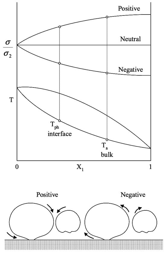
Figure 4.
Surface tension distribution over the composition of a binary mixture (top) and scheme of Marangoni flows between vapor bubbles (bottom); see ref. [27]. Reproduced from Fujita Y., Bai Q. Bubble dynamics and heat transfer in boiling. In Proceedings of the 12th IHTC 2002; 1:93-104. Copyright © 2002 Elsevier Masson SAS. All rights reserved.
Another poorly explored effect influencing heat transfer during boiling is the mutual interaction of the nucleation sites. As shown by Ustinov and Mitrovic [28,29], highly efficient micro pins surfaces may provide potential nucleation sites in large amounts, leading to the creation of bubble chains. Such chain nucleation could be explained by Equations (1)–(4), when a nucleation site activates the adjacent one, as the value of an energy barrier given by Equation (2) is lower in this case. It is easier for a vapor bubble to be created between the micro pins when a nucleation site is provided with both liquid and a vapor nucleus.
3. Introduction of the System for Classification of Enhanced Boiling Surfaces
Upon the above-presented brief analysis of processes underlying the nucleation and influencing the heat transfer, a new system for the classification of enhanced boiling surfaces is proposed as presented in Figure 5. All surface modifications are divided into three groups, which will be discussed with examples in more detail in this section. These groups are the following:
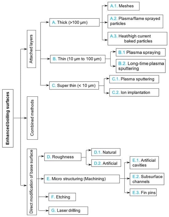
Figure 5.
Classification of modified boiling surfaces.
- –
- Attached layers, when a new layer of any kind is attached to the base surface;
- –
- Direct modifications, obtained by a direct change in the surface;
- –
- Combinations of these two.
This grouping is determined by the production technology resulting in some common properties of those surfaces. Any attached layer and the base material have binding forces between them, which causes effects such as dislocation, detachment, and subsequent performance drop after multiple cycles of warming up and cooling down. As the material of an attached layer often differs from the base surface material, they have different heat expansion coefficients. Next, the temperature field of a modified surface has noticeable gradients during boiling, so the attached layers usually detach from the base wall after a certain period of time.
From this point of view, the second group, the direct modification of the base surface, is preferable. However, the majority of surface modification technologies, attributed to this group, are, in general, more complex and expensive for production. The question of the stability of these modifications also remains open, as such data are practically absent from the literature. Both of these directions in enhanced surface production have been subjects of research for a long time in regard to their usability on an industrial scale and fouling characteristics.
3.1. Attached Surface Layers
Depending on the thickness, attached layers providing the heat transfer enhancement could be divided into three subgroups (see Figure 5). Layers with different thicknesses enhance heat transfer at different stages of a vapor bubble’s growth through different physical mechanisms. As mentioned above, the size of a cavity that supports the initial nucleation is about 10−6 m. One may accept this value as a lower border for “super-thin” layers and its 10-fold value as a lower border for “thick” layers. All the layers with thicknesses in between would belong to the thin layer group.
Taking such grouping, one can see that super-thin layers affect the energy barrier given by Equation (2) for the creation of a nucleus through the surface wettability, but have no influence on the surface roughness, which could result in a preferable geometrical place for nucleation. Thin layers affect both the wettability and the roughness of the surface. They can support the growth of vapor bubbles only during the first stages of growth. Thick layers form a complex three-dimensional porous matrix where nucleation can occur at any place.
- A.
- Thick layers
Thick layers are easy to obtain on a surface as their production does not require sophisticated technologies. However, thick layers, having porous structures, suffer negative phenomena such as vapor lock-up and the boiling crisis inside themselves at high heat fluxes. This happens due to the complex two-phase counterflows in a thick, porous layer. Vapor cannot leave the layer quickly, especially at high heat fluxes, so liquid cannot penetrate the structure and wet its base. For such structures, the critical heat flux sometimes decreases appreciably, and the heat transfer coefficients are lower. The types of thick layers are described below.
- A.1.
- Layers of meshes
Meshes are one of the easiest-created surface enhancers on flat boiling surfaces and tubes. Such an enhancement technique was used by Franco et al. [30]. The porous coating was obtained with the superposition of several layers of wire nets on a circular heat transfer surface. The grids were pressed on the heater surface. The structure shown in Figure 6 is commonly used in filtering techniques and is available in a wide range of geometrical parameters and materials. As materials for the metallic wire mesh, stainless steel (AISI 304), aluminum, copper, and brass were used. The effect of the height of the wire mesh structure has been tested by changing the number of net layers.
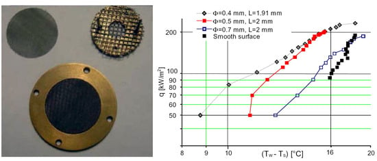
Figure 6.
Mesh structures (left) and corresponding boiling curves (right) with R141b at 1 bar; see ref. [30]. Reproduced with permission from [30]; published by Elsevier Inc., 2005.
The best performance was found for nets containing three to seven layers of wires with diameters between 0.25 mm and 0.40 mm and mesh aperture of approximately 2 mm. A possibility has been confirmed to separate vapor and liquid flows and to increase the critical heat flux (CHF) by means of a finer wire net placed on the heated surface and larger wire nets on the upper levels. An increase in CHF of up to 40% has been experimentally obtained. A larger number of mesh layers (despite the increased heat transfer surface) sometimes caused an earlier boiling crisis due to the complex two-phase flows inside the structure. Therefore, enhancement capability for such a meshed surface decreases with increasing heat flux.
In an earlier work of Labuntsov et al. [31], meshes made of fluorocarbon polymer were used to stabilize and enhance the boiling of water at pressures of 36 mbar and 200 mbar. This allowed for the decrease in the wall temperature at boiling inception from 25 K for a plain surface to 3.5 K for a surface with hydrophobic meshes; at the same time, the critical heat flux decreased drastically.
- A.2.
- Plasma/flame-sprayed particles
Another means of boiling improvement is a plasma- or flame-sprayed layer of metallic particles on the base substrate. Hwang et al. [32] report experimental data on the boiling of n-pentane at atmospheric pressure upon enhanced surfaces with loosely packed, shaken, or pressed copper particles with diameters between 40 μm and 80 μm, plasma-sprayed on the base copper surface. The layer thickness was between 3 and 5 diameters of a particle, and it was uniformly disposed on the base surface (see Figure 7).
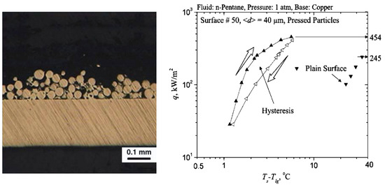
Figure 7.
(Left)—micrograph of side cross-section of porous-layer coating; (right)—the corresponding boiling curve [32]. Reproduced with permission from [32]; published by Elsevier Ltd., 2005.
The enhancement of the boiling process by a porous layer of particles is mainly associated with the rise in the number of nucleation sites in comparison to a smooth surface. For all the coatings, as found by Hwang et al. [32], the critical heat flux (CHF) is about 1.8 times higher than for a plain surface. Hysteresis for modified surfaces was experimentally detected (Figure 7), which is typical for this subgroup of modified surfaces. Hwang et al. [32] suggest that the presence of uniform porous coating influences the hydrodynamic (macroscale) stabilities in a way that the statistically critical Rayleigh–Taylor wavelength decreases. It is also possible that the vapor fraction increases in a manner that statistically causes a decrease in the dominant interfacial wavelength.
Liter et al. [33] extended the method of plasma or flame particles spraying to obtain modulated porous coatings. Figure 8 represents SEM photographs of tested surfaces with single- and dual-height-modulated porous-layer coatings.
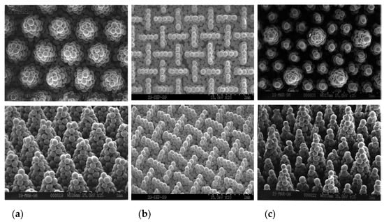
Figure 8.
SEM photos of single-height- (a,b) and dual-height (c) modulated porous coatings. Bottom—perspective view; top—top view of coatings [33]. Reproduced with permission from [33]; published by Elsevier Science Ltd., 2001.
The porous layers contain 200 μm spherical particles molded into conical stacks (Figure 8a,c) or tapered walls (Figure 8b). Experimental results presented by Liter et al. [33] showed that the modulated porous coating with optimized size, shape, and distribution increases the critical heat flux 3 times and decreases the boiling inception superheat from 2 to 2.5 times in comparison to a plain surface.
Along with metallic particles, other materials can be sprayed with plasma or flame flow on the base surface. Chang et al. [31] have produced several enhanced boiling surfaces on a square heater combining silver flakes, epoxy, isopropyl alcohol, diamonds, copper, aluminum, and methylethylketone. The applied sizes of particles in coatings were 1 μm to 20 μm for aluminum, 1 μm to 50 μm for copper, 8 μm to 12 μm for diamond, and 3 μm to 10 μm for randomly oriented layers of silver flakes. All coatings were tested with FC-72 at atmospheric pressure. The microporous enhanced surfaces showed about an 80–90% reduction in incipience superheat, about a 30% enhancement of the nucleate boiling heat transfer coefficient, and about a 100% enhancement in CHF over a plain surface. This enhancement was due to the creation of microporous structures on the heater surface that significantly increased the number of active nucleation sites. It is obvious that the wettability of coated surfaces changes greatly as well. The great disadvantage of the specific coverings is the presence of volatile components in their composition, like alcohol and epoxies. Although Chang and You [34] undertook some measures to ensure stable operation during tests, one may expect a substantial performance decrease over time (already after a time span of 100 h of work).
- A.3.
- Heat/high current baked particles
The further technological development of the plasma/flame spraying of particles to the base surface involves baking them with heat or high current. This can be carried out in a stove at temperatures of about 80% of the melting values, or by passing high currents through the surface with the particles. This provides stronger attraction forces between the particles themselves and the particles with the wall. This technology allows for the enhancement of the inner tube surface and other hard-to-access surfaces. The typical microstructure obtained as a result of this process is depicted in Figure 9.
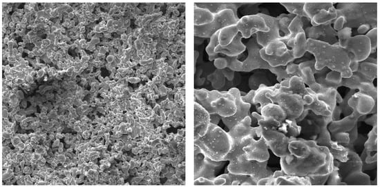
Figure 9.
SEM photographs of surfaces with high-current-baked copper particles; (left)—top view, zoom 500×, (right)—top view, zoom 1000× [35]. Reproduced with permission from [35]; published by Edizioni ETS, 2000.
Kuzma-Kichta et al. [35] report on the experiments on the flow boiling of water on surfaces covered with high-current-baked particles. The sintered porous coatings (Figure 9) of a thickness from 0.12 mm to 0.4 mm consisting of stainless steel and copper were tested at mass flow densities of 20 kg/m2s to 10,000 kg/m2s, pressures of 0.1 MPa to 6.0 MPa, and thermodynamic steam qualities of −0.3 up to 1.3. The strong nonlinearity of performance was detected for all types of surface modifications of this subgroup (see Figure 5). The authors suggest the optimization of such types of modified surfaces for every single application as the boiling crisis occurring inside the structure can decrease the overall heat transfer performance in some cases.
- B.
- Thin layers
The next subgroup of modified surfaces according to Figure 5 comprises thin layers attached to the base surface. This group encompasses layers with thicknesses between 10 μm and 100 μm. Physically thin layers could enhance the boiling heat transfer: (i) at the bubble origin, providing preferable physical and chemical conditions for initial nucleation, and (ii) at the first stages of bubble growth, supporting the mass heat flux inside a vapor bubble in the TPL region.
Such layers can be obtained only using modern technologies developed over the last few decades. There are at least two possibilities to create attached enhancing layers to the base surface, namely the process of plasma spraying small particles and plasma sputtering. During the plasma spraying, very fine particles are needed with simultaneous layer thickness control. Plasma sputtering in turn is a relatively slow process, and it takes tens of hours to produce an enhancing layer of the appointed thickness.
- B.1.
- Plasma spraying
Bouyer et al. [36] investigated several plasma-sprayed coatings with different properties and thicknesses. An example of such a surface is presented in Figure 10—the surface covered with the copper porous layer with a thickness of 51 µm. All surfaces were tested with the refrigerant R134a, boiling at saturation temperatures of −20 °C, 0 °C, and 20 °C. The enhancement ratio to the smooth tube as a function of heat flux is presented in Figure 10c. It can be seen that the thinnest plasma-sprayed coating (labeled with E in Figure 10c) has the most stable performance with the increasing heat flux. As mentioned earlier, such behavior can be attributed to the complex counterflows of vapor and liquid inside the porous matrix at high heat fluxes, worsening the supply of nucleation sites with liquid, which is practically absent for the thinner layer E.
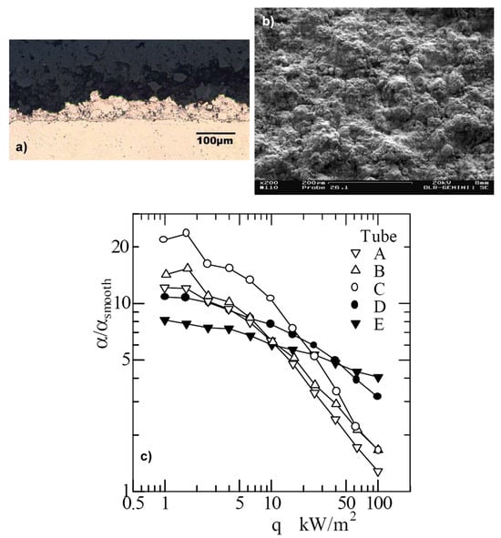
Figure 10.
Side (a) and top (b) views of plasma-sprayed coating E with a thickness of 51 µm; (c) enhancement factor of tested plasma-sprayed surfaces [36]. Reproduced with permission from [36]; published by ASM International, 2003.
- B.2.
- Plasma sputtering
Another way to create a thin enhancing layer on the base surface is the plasma sputtering process. However, there are no experimental investigations in the literature on boiling upon surfaces with plasma-sputtered layers with thicknesses between 10 µm and 100 µm to the knowledge of the authors. The main reason for that seems to be the fact that plasma sputtering is a very time-consuming process. It takes tens of hours to produce a sample with a thickness of even below 1 µm. The creation and testing of such surfaces could be the subjects of future investigations, as their advantage may be in a very precise adjustment of the boiling inception superheat through variation in the energy barrier (2).
- C.
- Super-thin layers
- C.1.
- Plasma sputtering
As mentioned in the previous section, the plasma sputtering process offers some interesting possibilities insofar as the creation of surface enhancers. Layers with a thickness of up to 10 µm are proposed to count as super-thin in accordance with the classification system accepted in this work (see Figure 5). Super-thin layers of just several nanometers in thickness could be strong enhancers of surface boiling heat transfer, especially in combination with some other means of enhancement. For example, they could be used with microstructured or UV-irradiated surfaces. Super-thin layers can affect the initial nucleation through the surface force field, changing its potential depending on the material properties of the applied surface layer and its thickness. Therefore, there is a large field for studies in nucleate boiling heat transfer at surfaces with applied super-thin enhancing layers.
Takata et al. [37] prepared surfaces, sputtered with TiO2 and TiO2 + SiO2, and investigated the evaporation of a water droplet on them. The sputtered layers’ maximal thicknesses were 250 nm and 275 nm, respectively. The obtained surfaces were disposed of under the UV irradiation, and the contact angles with water were subsequently decreased. This effect was called “photo-induced hydrophilicity” by Takata et al. [37]. After shielding the surfaces from the UV radiation, they recovered their properties back in a few hours (see Figure 11).
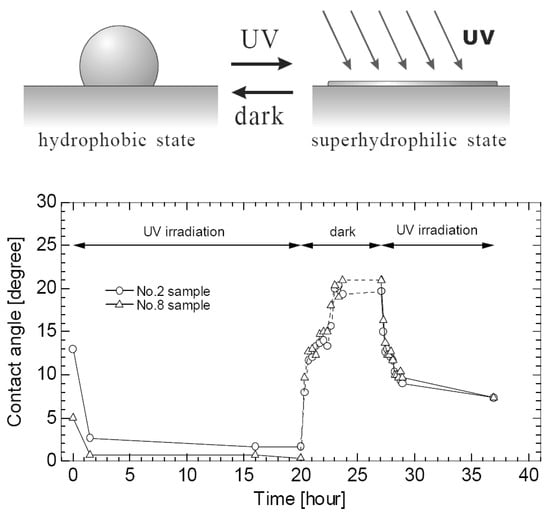
Figure 11.
(Top): schema of the photo-induced hydrophilicity; (bottom): change in contact angle of TiO2-sputtered surface [37]. Reproduced from Takata, Y. et al. Evaporation of Water Drop on Photo-Induced Hydrophilic Surface. Proc of 12th Int. Heat Transfer Conf. Grenoble 2002; 3:413-418. Copyright © 2002 Elsevier Masson SAS. All rights reserved.
Super-thin sputtered and UV-irradiated layers were found to decrease evaporation times greatly. The enhancement method of Takata et al. [37], consisting of a combination method of plasma sputtering and UV radiation, would be a promising topic for future investigations of boiling characteristics of a surface covered with a super-thin enhancing layer.
- C.2.
- Ion implantation
The last technology that will be considered in the group of attached enhancing layers is ion implantation. This is a relatively novel technology developed during the last few decades, and it lies on the border between attached enhancing layers and direct surface modifications (see Figure 5).
During the implantation process, the base solid surface is bombarded by ions with energies in the range between keV and MeV. The ions penetrate the surface at depths between 10 nm and 1000 nm depending on their energy and the relation of their mass to the mass of the base surface atoms. As the implanted layer thickness is below 1 µm, its thermal resistance is negligible. This layer exists in the state of a solid solution, so there is no obvious interface between the base metal and the layer; therefore, it is not easily removed (see Mueller-Steinhagen and Zhao [38]).
No systematic studies of boiling heat transfer enhancement were carried out with the ion-implanted surfaces. However, Mueller-Steinhagen and Zhao [38] have tested such surfaces for fouling during the pool boiling of CaSO4–water solutions. Figure 12 gives the basic ideas about low fouling performance and long-time working stability of the ion-implanted stainless-steel surface. Some interesting results could be obtained in boiling experiments with the ion-implanted surfaces, especially in combination with other enhancing techniques.
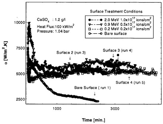
Figure 12.
Effect of implantation conditions on heat transfer coefficient [38]. Reproduced with permission from [38]; published by Elsevier Science Ltd., 1997.
3.2. Direct Modification of Base Surface
As stated above, direct surface modifications are preferable to the attached enhancing layers, as there are no changes in binding forces between the enhancer and the base surface. However, the surface force field could be essentially varied by the changed geometry and/or the chemical composition of the enhanced surface, correspondingly affecting the energy barrier (2). One must note that directly modified surfaces often have coarser structure than the surfaces with applied layers. The majority of direct modifications require contact methods of surface treatment, such as cold machining, for example. Therefore, the linear scales of surface structure elements are limited to the size of treating tools.
- D.
- Roughness
Historically, the very first enhancement during boiling was observed upon scratched and rough surfaces. At present, a relatively large information databank is accumulated for the boiling heat transfer upon rough surfaces. However, the main remaining question is the representation method of a real rough surface. Normally, the scalar parameter roughness is used for the complex three-dimensional microstructure of a real surface representation. It is evidently not adequate for the next-generation models of surface boiling. Some possible solutions to this fundamental problem will be considered in this section.
It is proposed to distinguish between natural and artificial roughness types. Natural roughness is that of untreated surfaces. Any kind of surface roughening changes its classification to the subgroup of artificial roughness (see Figure 5). It is known that the number of nucleation sites on a surface is directly proportional to its roughness.
- D.1.
- Natural roughness
Using the fractal model of Mandelbrot, Solodov [39] has built up a realistic heat transfer boiling surface (see Figure 13). This method is also used in the computer modeling of surfaces.
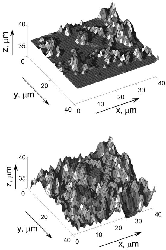
Figure 13.
Realistic representation of an irregular surface [39]. Copyright © 1999 From Computer Model of Nucleate Boiling by Solodov, A.P. Reproduced by permission of Taylor and Francis Group, LLC, a division of Informa plc.
Therefore, Solodov [39] proposed a computer model of nucleate boiling heat transfer, where a surface is characterized by the fractal dimension with a numerical value between 2 and 3. The linear distance between nucleation sites L is given by Solodov’s model [36] as follows:
In Equation (7), C is a fitting constant, RS is a linear scale, and Rcr is the critical vapor bubble diameter; Rcr = d/2, where d is given by Equation (1).
The constant C was determined in accordance with experimental data at 1 bar and used for calculation at pressures of up to 200 bars. The calculation results were compared with experimental data for the boiling of water on a silver tube and copper tube coated with nickel and chrome, and on stainless steel tube (Figure 14). Using the fractal dimension D = 3 (corresponding to a three-dimensional object) allows for the obtaining of good agreement with experimental data.
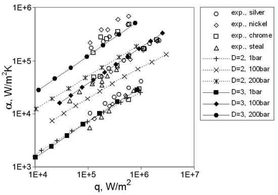
Figure 14.
Comparison of a fractal computer model with experimental data [39]. Copyright © 1999 From Computer Model of Nucleate Boiling by Solodov, A.P. Reproduced by permission of Taylor and Francis Group, LLC, a division of Informa plc.
Introducing the fractal description of the heating surface Solodov [39] correctly simulates the decrease in the distance between active nucleation sites with increasing pressure, improving the calculation of the heat transfer coefficient with nucleate boiling.
Some other attempts to use the fractal dimension for a boiling surface representation are known. Yu and Cheng [40] have proposed another calculation model for boiling heat transfer from a real surface utilizing the concept of fractal dimension. An a posteriori analysis by Yu and Cheng [40] proposes the calculation of the fractal dimensions from a photograph of a surface via the box-counting method. They found the fractal dimension to be between one and two, i.e., as for a two-dimensional object, and considered the active cavities, formed on the heated surfaces, to be analogous to pores in porous media. Based on this idea, Yu and Cheng [40] took advantage of the developments in the fractal theory of porous media. Using their model, they succeeded in fitting the experimental data (Figure 15).
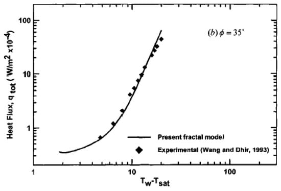
Figure 15.
Comparison of the fractal model with experimental data [40]. Reproduced with permission from [40]; published by ASME International, 2002.
Therefore, it seems that the universal way of representing a real surface as well as a structured one could be the above-mentioned approach using the fractal dimension. However, no agreement exists among the researchers over the basic principles of the approach; so, further investigations are required.
Some non-metallic materials with natural structures are utilized as boiling heat sinks for the needs of electronic device cooling. El-Genk and Parker [41] report on experimental data on the enhanced boiling of high-wetting HFE-7100 dielectric liquid on porous graphite at atmospheric pressure. The authors apply this liquid as a substitute for FC-72. The structure of porous graphite contains many interconnected pores and re-entrant-like cavities, which enhance boiling in two ways: (i) it is a preferable place for nucleation itself and (ii) it provides entrapped vapor. Figure 16 presents SEM photos of porous graphite, along with the boiling curves of HFE-7100 for saturated boiling at atmospheric pressure.
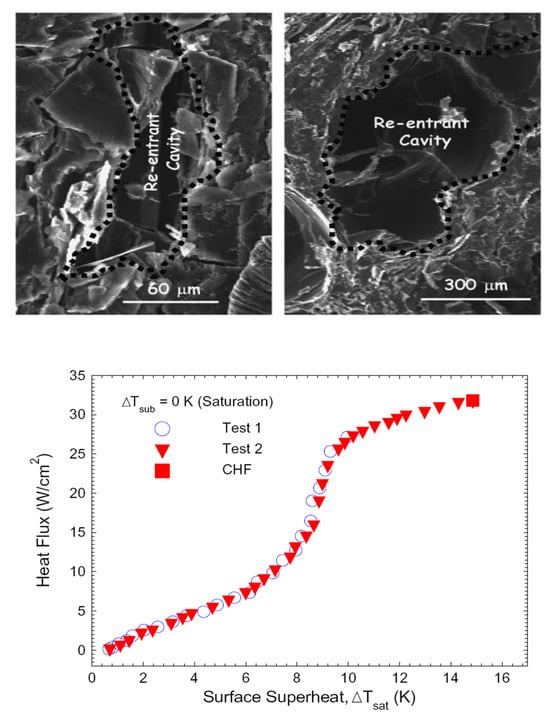
Figure 16.
Heat transfer improvement by a graphite layer [41]. (Top): SEM images of the porous graphite (PG) surface. (Bottom): boiling curves for saturation boiling of HFE-7100 on PG. Reproduced with permission from [41]; published by Elsevier Ltd., 2005.
The significant performance drop of the porous graphite structure may be predicted after long-time usage as the entrapped air is removed from it. This type of structure is not always applicable in industrial use, as the technology of the porous graphite application to a tube and other non-flat surfaces has not yet been developed. Boiling curves for this structure are characterized by classical temperature rise with increasing heat flux.
- D.2.
- Artificial roughness
Artificially roughened surfaces are relatively well explored. The question of such surface representation remains open, although the fractal approach mentioned above for a naturally rough surface seems to remain applicable here. Another way to represent a surface is the method developed by Luke et al. [14]. In this method, a virtual ball of a certain diameter, rolling over a real surface, is supposed to provide a smoothing curve for a two-dimensional representation, and a smoothing surface for a three-dimensional representation, of a surface (see Figure 17). The virtual ball procedure seems to be more complex in use and subsequently less universal for enhanced surfaces. It is also not deprived of the subjective factors of using the “proper” ball radius (for more details, see Luke et al. [14]).
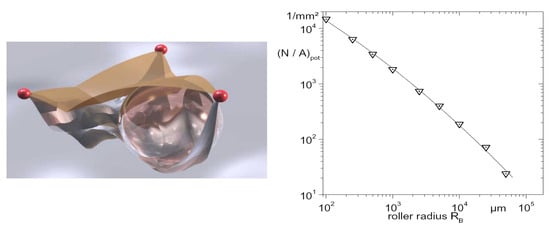
Figure 17.
(Left): depiction of a cavity. (Right): number of potential sites N/Apot as a function of the roller radius RB [14]. Reproduced from Luke, Andrea et al. Size Distribution of Active and Potential Nucleation Sites in Pool Boiling. Heat transfer 2002. Proceedings of the Twelfth International Heat Transfer Conference 2002; 3:383-388. Copyright © 2002 Elsevier Masson SAS. All rights reserved.
- E.
- Machined microstructures
Modern mechanical engineering allows for the creation of different kinds of subsurface structures with different characteristic sizes and complexity. The advantage of machining is the relative cheapness and speed of the production process. However, the obtained structures are limited in linear scale to the size of the processing tool. For supporting the bubble nucleation and providing the largest possible amount of potential nucleation sites, machined surfaces must have the characteristic size of a structure element about the critical bubble radius, given by Equation (1). The creation of such a small microstructure is only possible with several new technologies, which will be considered later in this section.
- E.1.
- Artificial cavities
Artificial cavities are well known to intensify heat transfer during surface boiling. Shoji and Takagi [42] have investigated bubbling features from a single artificial cavity of different microgeometries (see Figure 18).
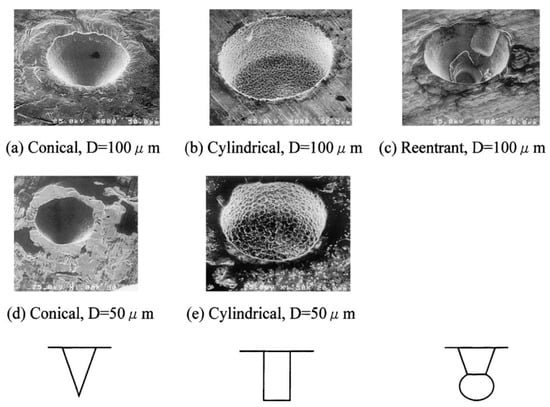
Figure 18.
Variations in artificial cavities [42]. Reproduced with permission from [42]; published by Elsevier Science Ltd., 2001.
All cavities were manufactured on the surface of a copper disk with a 10 mm diameter and a 0.1 mm thickness. Conical cavities were produced by pressing a diamond bit on the surface via a micro-hardness meter and had diameters of 50 µm or 100 µm and depths of 30 µm or 50 µm, respectively. Cylindrical cavities of the same sizes were produced by the micro-electrical discharging machine. Re-entrant cavities were produced by a combination of those two means and had a diameter of 100 µm and depth of 50 µm.
The apparatus of nonlinear dynamics analysis was applied by Shoji and Takagi [39] to evaluate the experimental measurements of temperature under an artificial cavity. Using this type of analysis, Shoji and Takagi [39] have proven stable nucleation from cylindrical and re-entrant cavities with low-temperature oscillations. At the same time, conical cavities demonstrated strong intermittence in bubbling phenomena and larger surface temperature fluctuations. The lowest superheats were required for boiling inception on a surface with re-entrant cavities. Conclusions of the analytical results were confirmed by Shoji and Takagi [42] based on visual observations (see Figure 19).
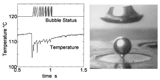
Figure 19.
(Left): temperature-time series for conical cavity D = 50 µm, P = 1.7 W. (Right): bubbling from a conical cavity D = 100 µm, P = 2.5 W [42]. Reproduced with permission from [42]; published by Elsevier Science Ltd., 2001.
Although the industrial use of enhanced surfaces with artificial cavities prepared with specific technologies described by Shoji and Takagi [42] seems to be questionable, they provide some important insights. In the case of the creation of a real enhancing heat transfer surface, cavities shapes and geometry optimization are required for every particular application.
- E.2.
- Subsurface channels
One of the disadvantages of surfaces with artificial cavities, especially re-entrant ones, is that they are hardly filled with liquid during boiling at high heat fluxes. To overcome this problem, the subsurface channels were proposed. They can act in the same way as re-entrant cavities and at the same time supply neighboring cavities under the heat transfer surface with liquid.
Webb and Chien [43] visualized the boiling process upon the enhanced surfaces with subsurface channels. They used a transparent cover to obtain insight into a subsurface tunnel. A photo of this process is presented in Figure 20a, and some experimental data on heat transfer are shown in Figure 20b. For low heat fluxes (q ≤ 10 kW/m2), the suction–evaporation mode of boiling occurs in over 70–90% of the active tunnels. The remaining region has oscillating menisci. For higher heat fluxes, the evaporation of liquid menisci in the tunnel corners is the principal boiling mechanism for the surfaces with subsurface channels.
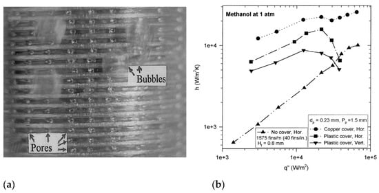
Figure 20.
(a) Saturated boiling on a vertical tube at 1 atm, q = 5 kW/m2; (b) boiling of methanol on the enhanced surface at 1 atm [43]. Reproduced with permission from [43]; published by Elsevier Science Inc., 1999.
Several commercially available tubes with undersurface re-entrant channels of different configurations were tested by Chen et al. [44] (see Figure 21). The experiments were conducted with propane, isobutane, and their binary mixtures at saturation temperatures between 243 K and 293 K.
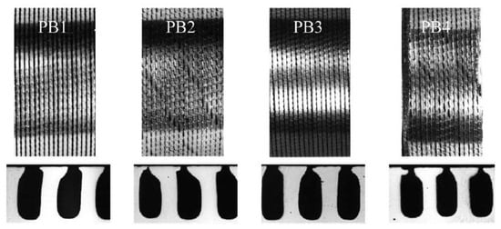
Figure 21.
Surface topology of enhanced tubes (upper: structured surface; lower: corresponding subsurface channels) [44]. Reproduced with permission from [44]; published by Elsevier Science Inc., 1999.
The results of this investigation are presented in Figure 22. Hysteresis was detected in all boiling regimes, as well as nonlinearity in enhancement, compared with a smooth tube. In some boiling modes, these enhanced surfaces even exhibited the degradation of the boiling performance and have lower heat transfer coefficients than smooth ones (see Figure 22b). This effect is especially noticeable with boiling mixtures.
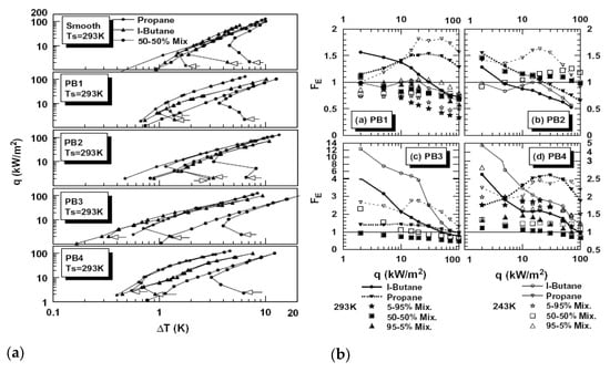
Figure 22.
(a) Boiling curves for increasing and decreasing heat fluxes. (b) Enhancement factor for four tested surfaces [44]. Reproduced with permission from [44]; published by Elsevier Science Inc., 1999.
- E.3.
- Fin pins
Pin-finned surfaces form a new family of enhanced boiling surfaces. Guglielmini et al. [45] investigated the boiling of saturated FC-72 on square cross-sectioned pin fin arrays with different configurations of the copper surface. Obtained using an electro-discharging machine, pins were 3 mm or 6 mm high, 0.4 mm to 1.0 mm wide, and uniformly or non-uniformly spaced on the base copper surface (see Figure 23).
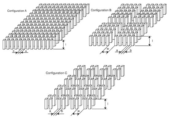
Figure 23.
Configurations of extended surfaces [45]. Reproduced with permission from [45]; published by Éditions scientifiques et médicales Elsevier SAS, 2002.
It was found that in the case of extended surfaces composed of uniformly spaced fins, higher fins appear to work slightly better, particularly in proximity to the maximum heat flux. When fin width and spacing decrease, the heat transfer rate increases; at high heat fluxes, however, the overall heat transfer coefficients reduce.
At low heat fluxes, the finned surfaces show an appreciably higher overall heat transfer coefficient than a flat surface. All tested surfaces demonstrate strong nonlinear behavior in terms of heat transfer coefficients (see Figure 24). This can be attributed to several factors, simultaneously affecting the bubbling phenomena. The large heat transfer surface generally leads to higher heat transfer coefficients. However, a reduction in the heat transfer area through decreasing the pins’ diameter and spacing leads to better wetting of the heat transfer surface.
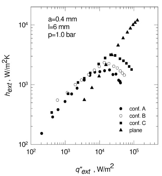
Figure 24.
Effect of surface configuration on heat transfer coefficient at p = 1.0 bar for fin-pinned surfaces [45]. Reproduced with permission from [45]; published by Éditions scientifiques et médicales Elsevier SAS, 2002.
Surfaces examined by Guglielmini et al. [45] had pins with spacing about 100 times larger than the critical vapor bubble diameter, obtained from Equations (1) and (2). This means that the pins support the growing vapor bubbles rather than the initial nucleation process. Nonlinearity in performance demands geometry optimization for a certain application.
A surface obtained with a novel machining method, which leaves no chippings or cutting waste for a metallic material, was investigated by Ustinov et al. [46,47], with the boiling of R134a both for pool and flow boiling conditions (see Figure 25). The basic structural surface element was a fin continuously rolling around the surface, having a thickness of 0.3 mm to 0.6 mm, a height of about 1.8 mm, and a step between 0.6 mm and 1.2 mm. Experiments were conducted at pressures of up to 3 bar, heat fluxes of up to 125 kW/m2, and mass flow rates between 2 and 3 kg/(m2s) in a real evaporator of a heat pump.
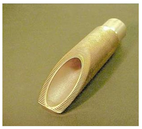
Figure 25.
Finned enhanced boiling surface, obtained with no-waste cutting technology; see refs. [46,47]. Reprinted from Proceedings of the 17th International Conference on Heat and Mass Transfer (IHTC-17), Ustinov, Alexander, et al., Investigation of chaotic flow boiling dynamics using reflected laser probing near microstructured surface, 150–180, Copyright (2023), with permission from Begell House, Inc. (Danbury. CT, USA).
In [46,47], it was shown that enhancements in heat transfer coefficients of up to 4 times in comparison with theoretical values are attributed to the extended surface, which provides intensive nucleation already at low heat fluxes (see Figure 26). Another effect observed in [46,47] was the bubble departure size distribution: an enhanced surface demonstrates 50-times-wider spectra in comparison with a smooth surface under the same conditions, generating a variety of bubbles.
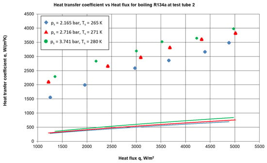
Figure 26.
Heat transfer coefficients for flow boiling of R134a in a heat pump evaporator at different saturations [47]. Reprinted from Proceedings of the 17th International Conference on Heat and Mass Transfer (IHTC-17), Ustinov, Alexander, et al., Investigation of chaotic flow boiling dynamics using reflected laser probing near microstructured surface, 150–180, Copyright (2023), with permission from Begell House, Inc.
- F
- Etching
Mitrovic [4] has produced and tested the photo-etched surfaces with the refrigerant R11 (CF2Cl3) on a flat heater surface provided with artificial nucleation sites (see Figure 27). The surface cavities (diameter 180 μm, depth 120 μm, and density 460 cm−2, approximately) were arranged hexagonally. The walls of the cavities were not smooth but covered with a fine structure that largely governed the wall superheat.
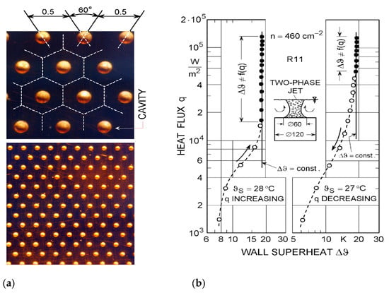
Figure 27.
(a) Cavity pattern on the heating plate, tested with R11; (b) boiling characteristics of the tested surface [4]. Reproduced from Mitrovic J. How to create an efficient surface for nucleate boiling? International Journal of Thermal Sciences 2006; 45(1):1–15. Copyright © 2006 Elsevier Masson SAS. All rights reserved.
The constancy of the wall superheat has been observed at relatively high heat fluxes (see Figure 27b). In the case of increasing heat flux, the surface cavities were activated at nearly the same heat flux value. Bubbles detached almost simultaneously on the whole surface, resulting in a piston-like boiling oscillation. This boiling behavior was only observed in the horizontal orientation of the heating surface.
Wei et al. [48] fabricated micro-pin fins with the dimensions of several tens of microns on the surface of a square silicon chip (10 × 10 × 0.5 mm3) using the dry etching technique. The surfaces were tested with the nucleate pool boiling of degassed or gas-dissolved FC-72 at atmospheric pressure and subcoolings of up to 45 K. Depending on etching conditions, some pinned surfaces were additionally provided with the submicron scale roughness (see Figure 28).
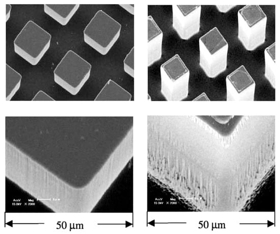
Figure 28.
SEM view of silicon chips with micro-pin fins [48]. Reproduced with permission from [48]; published by Elsevier Science Ltd., 2003.
The micro-pin fins were effective in enhancing heat transfer in the nucleate boiling region and increasing critical heat flux. The boiling curve of the micro-pin-finned chip was characterized by a very sharp increase in the heat flux with increasing wall superheat. The slope of the boiling curve was somewhat smaller for the chip with the smallest fin-height-to-fin-pitch ratio (see Figure 29). The wall superheat in the fully developed nucleate boiling region was lower for chips with a larger surface roughness on the fin flank. For the chips with high fins, however, the boiling curve showed a bend in the high heat flux region, and the slope decreased significantly. The wall temperature at the CHF point was always less than the upper limit (≈85 °C) for a reliable operation of LSI chips.
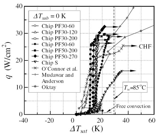
Figure 29.
Comparison of boiling curves; ΔTsub = 0 K, degassed [48]. Reproduced with permission from [48]; published by Elsevier Science Ltd., 2003.
The enhancing etching technology of Wei et al. [48] (although it provides almost constant wall superheats in the nucleate boiling mode) is applicable only to silicon surfaces. An analogous technology exists for metallic surfaces, however, and it will be considered further below in the article.
- G.
- Etching
The last direct surface treatment technique mentioned in this review is the machining of mini- and microchannels by laser drilling. Kandlikar et al. [49] used this technique to generate microcavities on the base copper surface (see Figure 30). The investigation presented by Kandlikar [49] aimed to study flow instabilities caused by nucleation in a channel, so the results were not presented in terms of heat transfer. Therefore, this could be an interesting topic for future investigations. Laser drilling was also used for silicon surfaces by Hwang and Moran [50], but the industrially applicable technology has not been available until recently. However, applying laser techniques results in a local melting of base material so that the solidification of the melt usually leads to smooth surfaces on the microscale, which are less effective in nucleate boiling applications.
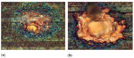
Figure 30.
Laser-drilled holes on microchannel surfaces [49]. (a) Average diameter of 8 μm; (b) average diameter of 22 μm. Reproduced with permission from [49]; published by ASME International, 2006.
3.3. Combined Methods
The last group of enhanced surfaces for boiling in accordance with the classification presented in Figure 5 consists of surfaces obtained with combined methods of treatment. Some methods mentioned above are the combined methods themselves, as almost every modern treatment technology is not simple and involves several different steps of fabrication.
An example of a successful application of combined methods is the enhanced surface described by Mitrovic et al. [4,5,6,7,8,15,28,29]. For the very first time, a novel microstructure for boiling applications was developed at the Institute for Thermal Process Engineering and Plant Technology of the University of Paderborn in joint work with the Institute for Nuclear Research in Dubna, Russia, and the company “μ-Technik” from Quedlinburg, Germany. The basic elements of the novel microstructure are micro-pins with exceptionally high pin density (see Figure 31). Several microstructured surfaces have been tested under the free convective pool boiling of liquids. The pin densities varied from 104 cm−2 up to 109 cm−2. The main process of the production technology of such a microstructure is galvanic deposition. One of the pursued aims was the development of the microstructure for evaporation processes by the experimental investigation of the boiling performance depending on the heat flux and properties of the liquid.
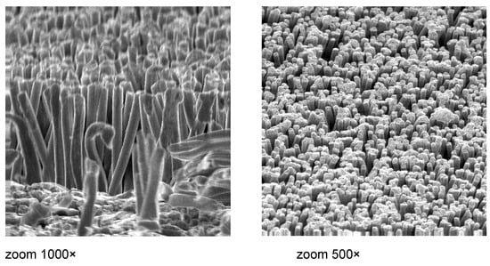
Figure 31.
SEM photos of microstructured surface, provided with micro-pins [51]. Reproduced with permission from [51]; published by Elsevier Inc., 2011.
4. Conclusions
This paper provides the original classification system of enhanced surfaces for boiling applications based on the common properties of different enhancement methods and the consideration of the basic physical principles governing nucleation. Modified surfaces can enhance the boiling heat transfer either by supporting the initial nucleation, which is a probabilistic phenomenon, or by enlarging the length of the three-phase-line (TPL) after a vapor bubble has been created and starts to grow.
Surfaces with structural elements of about critical vapor bubble diameter at given nucleation conditions are capable of providing a greater number of potential nucleation sites. They support the density fluctuations in a boiling liquid and increase the probability of initial nucleation. Larger geometry elements of enhanced surfaces are able to enhance heat transfer during bubble growth and departure. Micro-pinned enhanced surfaces seem to support both inceptive and growing vapor bubbles, demonstrating very large heat transfer coefficients.
The proposed classification system is universal and allows for the addition of new surface treatment techniques as they appear in the future.
Author Contributions
Conceptualization, A.U. and J.M.; methodology, A.U. and J.M.; investigation, all three authors; resources, J.M.; data curation, A.U. and D.U.; writing—original draft preparation, all three authors; writing—review and editing, A.U. and J.M.; visualization, D.U.; supervision, A.U. All authors have read and agreed to the published version of the manuscript.
Funding
This research received no external funding.
Conflicts of Interest
Author Alexander Ustinov was employed by the company Framatome GmbH. The remaining authors declare that the research was conducted in the absence of any commercial or financial relationships that could be construed as a potential conflict of interest.
References
- Thome, J.R. Enhanced Boiling Heat Transfer; Hemisphere: New York, NY, USA, 1990. [Google Scholar]
- Webb, R.L. Principles of Enhanced Heat Transfer; Wiley Int. Publication: Hoboken, NJ, USA, 1994. [Google Scholar]
- Webb, R.L. Odyssey of the enhanced boiling surface. ASME J. Heat Transf. 2004, 126, 1051–1059. [Google Scholar] [CrossRef]
- Mitrovic, J. How to create an efficient surface for nucleate boiling? Int. J. Therm. Sci. 2006, 45, 1–15. [Google Scholar] [CrossRef]
- Mitrovic, J.; Ustinov, A. Nucleate boiling heat transfer on a tube provided with a novel microstructure. J. Enhanc. Heat Transf. 2006, 13, 261–278. [Google Scholar] [CrossRef]
- Mitrovic, J.; Ustinov, A. Boiling features of a novel microstructure. In Proceedings of the 13th International Heat Transfer Conference, Sydney, Australia, 13–18 August 2006. [Google Scholar]
- Ustinov, A.; Mitrovic, J. Highly effective surfaces for boiling applications. In Proceedings of the 5th International Conference on Heat Transfer, Fluid Mechanics and Thermodynamics, Sun City, South Africa, 1–4 July 2007. [Google Scholar]
- Ustinov, A.; Mitrovic, J. Special boiling effects of novel microstructured surface. In Proceedings of the 5th European Thermal-Sciences Conference, Eindhoven, The Netherlands, 18–22 May 2008. [Google Scholar]
- Labuntsov, D.A. Heat transfer during nucleate boiling of liquids. Teploenergetika 1959, 12, 19–26. (In Russian) [Google Scholar]
- Wenzel, R.N. Resistance of solid surfaces to wetting by water. Ind. Eng. Chem. 1936, 28, 988. [Google Scholar] [CrossRef]
- Deriagin, B.V. On measurement of contact angle. Dokl. AN SSSR 1946, 51, 357–360. (In Russian) [Google Scholar]
- Deriagin, B.V.; Churaev, N.V.; Muller, V.M. Poverkhnostnie Sili—Surface Forces; Nauka: Moscow, Russia, 1987. (In Russian) [Google Scholar]
- Nelson, R.A. Do we doubt too little? Examples from the thermal sciences. Exp. Therm. Fluid Sci. 2001, 25, 255–267. [Google Scholar] [CrossRef]
- Luke, A.; Danger, E.; Gorenflo, D. Size distribution of active and potential nucleation sites in pool boiling. In Proceedings of the 12th International Heat Transfer Conference, Grenoble, France, 18–23 August 2002; Volume 3. [Google Scholar]
- Mitrovic, J.; Hartmann, F. A new microstructure for pool boiling. Superlattices Microstruct. 2004, 35, 617–628. [Google Scholar] [CrossRef]
- Labuntsov, D.A. Approximate theory of heat transfer for a developed nucleate boiling. Izv. AN SSSR OTN Energ. I Transp. 1963, 1, 58–71. (In Russian) [Google Scholar]
- Upot, N.V.; Rabbi, K.F.; Khodakarami, S.; Ho, J.Y.; Mendizabal, K.J.; Miljkovic, N. Advances in micro and nanoengineered surfaces for enhancing boiling and condensation heat transfer: A review. Nanoscale Adv. 2023, 5, 1232–1270. [Google Scholar] [CrossRef]
- Auracher, H.; Marquardt, W. Heat transfer characteristics and mechanisms along entire boiling curves under steady-state and transient conditions. Int. J. Heat Fluid Flow 2004, 25, 223–242. [Google Scholar] [CrossRef]
- Judd, K.; Kenning, D.B.R.; Ellepola, J.H.; McSharry, P.E.; Harden, J.V. Spatial-temporal analysis of nucleate pool boiling: Identification of nucleation sites using non-orthogonal empirical functions. Int. J. Heat Mass Transf. 2002, 45, 237–253. [Google Scholar]
- Kuzma-Kichta, Y.A.; Ustinov, A.K.; Ustinov, A.A. Analysis of interface oscillations during boiling. In Proceedings of the 12th International Heat Transfer Conference, Grenoble, France, 18–23 August 2002; Volume 3, p. 527. [Google Scholar]
- Ilyin, I.N.; Grivtsov, V.P.; Yaundalders, S.R. Holographic interferometry studies of temperature profiles in thermal boundary layer in free convection and bubble boiling. In Proceedings of the 7th International Heat Transfer Conference, Munchen, Germany, 6–10 September 1982; Volume 4, pp. 55–59. [Google Scholar]
- Mitrovic, J. On the profile of the liquid wedge underneath a growing vapor bubble and the reversal of the wall heat flux. Int. J. Heat Mass Transf. 2002, 45, 409–415. [Google Scholar] [CrossRef]
- Aus der Wiesche, S. Bubble growth and departure during nucleate boiling: The occurrence of heat flux reversal. In Proceedings of the 4th International Conference on Computational Heat and Mass Transfer, Paris-Cachan, France, 17–20 May 2005. [Google Scholar]
- Shoji, M. Studies of boiling chaos: A review. Int. J. Heat Mass Transf. 2004, 47, 1105–1128. [Google Scholar] [CrossRef]
- Mosdorf, R.; Shoji, M. Chaos in nucleate boiling—Nonlinear analysis and modeling. Int. J. Heat Mass Transf. 2004, 47, 1515–1524. [Google Scholar] [CrossRef]
- Barthau, G.; Hahne, E. Second order effects in an experimental study of nucleate pool boiling of R134a. In Proceedings of the 12th International Heat Transfer Conference, Grenoble, France, 18–23 August 2002; Volume 3, p. 683. [Google Scholar]
- Fujita, Y.; Bai, Q. Bubble dynamics and heat transfer in boiling. In Proceedings of the 12th IHTC, Grenoble, France, 18–23 August 2002; Volume 1, pp. 93–104. [Google Scholar]
- Ustinov, A.; Mitrovic, J. Boiling heat transfer enhancement by controllable tailoring of the TPL. In Proceedings of the 14th International Heat and Mass Transfer Conference, Washington, DC, USA, 8–13 August 2010. Conference Proceedings. [Google Scholar]
- Ustinov, A.; Mitrovic, J. Modeling of Boiling Heat Transfer from Microstructured Surfaces. In Proceedings of the 15th International Conference on Heat and Mass Transfer (IHTC-15), Kyoto, Japan, 10–15 August 2014; pp. 6379–6393, Conference Proceedings. [Google Scholar] [CrossRef]
- Franco, A.; Latrofa, E.M.; Yagov, V.V. Heat transfer enhancement in pool boiling of a refrigerant fluid with wire nets structures. Exp. Therm. Fluid Sci. 2006, 30, 263–275. [Google Scholar] [CrossRef]
- Labuntsov, D.A.; Yagov, V.V. Vapor bubbles dynamics at low pressures. Tr. MEI 1975, 268, 16–32. (In Russian) [Google Scholar]
- Hwang, G.-S.; Kaviany, M. Critical heat flux in thin, uniform particle coatings. Int. J. Heat Mass Transf. 2006, 49, 844–849. [Google Scholar] [CrossRef]
- Liter, S.G.; Kaviany, M. Pool-boiling CHF enhancement by modulated porous-layer coating: Theory and experiment. Int. J. Heat Mass Transf. 2001, 44, 4287–4311. [Google Scholar] [CrossRef]
- Chang, J.Y.; You, S.M. Enhanced boiling heat transfer from micro-porous surfaces: Effects of a coating composition and method. Int. J. Heat Mass Transf. 1997, 40, 4449–4460. [Google Scholar] [CrossRef]
- Kuzma-Kichta, Y.A.; Komendantov, A.S.; Bakunin, V.G.; Bartsch, G.; Goldschmidt, R.; Stein, M. Enhancement of heat transfer at boiling with porous coated surfaces. In Proceedings of the 3rd European Thermal Sciences Conference, Heidelberg, Germany, 10–13 September 2000; pp. 809–814. [Google Scholar]
- Bouyer, E.; Hanne, R.; Müller-Steinhagen, H.; Schäfer, D.; Asano, H. Improved Heat Transfer by RF Plasma Produced Structured Surfaces. In Proceedings of the International Thermal Spray Conference, Orlando, FL, USA, 5–8 May 2003; pp. 559–566. [Google Scholar]
- Takata, Y.; Hidaka, S.; Yamamoto, H.; Masuda, M.; Ito, T. Evaporation of Water Drop on Photo-Induced Hydrophilic Surface. In Proceedings of the 12th International Heat Transfer Conference, Grenoble, France, 18–23 August 2002; Volume 3. [Google Scholar]
- Mueller-Steinhagen, H.; Zhao, Q. Investigation of low fouling surface allows made by ion implantation technology. Chem. Eng. Sci. 1997, 52, 3321–3332. [Google Scholar] [CrossRef]
- Solodov, A.P. Computer Model of Nucleate Boiling. In Proceedings of the International Engineering Foundation, 3rd Conference, Irsee, Germany, 18–23 May 1999; pp. 231–238. [Google Scholar]
- Yu, B.; Cheng, P. A Fractal Model for Nucleate Pool Boiling Heat Transfer. J. Heat Transf. 2002, 124, 1117–1124. [Google Scholar] [CrossRef]
- El-Genk, M.S.; Parker, J.L. Enhanced boiling of HFE-7100 dielectric liquid on porous graphite. Energy Convers. Manag. 2005, 46, 2455–2481. [Google Scholar] [CrossRef]
- Shoji, M.; Takagi, Y. Bubbling features from a single artificial cavity. Int. J. Heat Mass Transf. 2001, 44, 2763–2776. [Google Scholar] [CrossRef]
- Webb, R.L.; Chien, L.-H. Visualization of pool boiling on enhanced surfaces. Exp. Therm. Fluid Sci. 1998, 16, 332–341. [Google Scholar]
- Chen, Y.; Groll, M.; Mertz, R.; Kulenovic, R. Visualization and mechanisms of pool boiling of propane, isobutane and their mixtures on enhanced tubes with reentrant channels. Int. J. Heat Mass Transf. 2005, 48, 2516–2528. [Google Scholar] [CrossRef]
- Guglielmini, G.; Misale, M.; Schenone, C. Boiling of saturated FC-72 on square pin fin arrays. Int. J. Therm. Sci. 2002, 41, 599–608. [Google Scholar] [CrossRef]
- Ustinov, D.A.; Sukhikh, A.-A.; Sidenkov, D.V.; Ustinov, V.A. Experimental study of the structure of vapor phase during boiling of R134a on heat exchange surfaces of heat pump. J. Phys. Conf. Ser. 2017, 891, 012032. [Google Scholar] [CrossRef]
- Ustinov, A.; Ustinov, D.; Sukhikh, A.; Kuzma-Kichta, Y.; Ustinov, V. Investigation of chaotic flow boiling dynamics using reflected laser probing near microstructured surface. In Proceedings of the 17th International Conference on Heat and Mass Transfer (IHTC-17), Cape Town, South Africa, 14–18 August 2023. [Google Scholar] [CrossRef]
- Wei, J.J.; Honda, H. Effects of fin geometry on boiling heat transfer from silicon chips with micro-pin-fins immersed in FC-72. Int. J. Heat Mass Transf. 2003, 46, 4059–4070. [Google Scholar] [CrossRef]
- Kandlikar, S.G.; Kuan, W.K.; Willistein, D.A.; Borrelli, J. Stabilization of flow boiling in microchannels using pressure drop elements and fabricated nucleation sites. J. Heat Transf. 2006, 128, 389–396. [Google Scholar] [CrossRef]
- Hwang, U.P.; Moran, K.F. Boiling heat transfer of silicon integrated circuits chip mounted on a substrate. ASME HTD 1981, 20, 53–59. [Google Scholar]
- Ustinov, A.; Ustinov, V.; Mitrovic, J. Pool boiling heat transfer of tandem tubes provided with the novel microstructures. Int. J. Heat Fluid Flow 2011, 32, 777–784. [Google Scholar] [CrossRef]
Disclaimer/Publisher’s Note: The statements, opinions and data contained in all publications are solely those of the individual author(s) and contributor(s) and not of MDPI and/or the editor(s). MDPI and/or the editor(s) disclaim responsibility for any injury to people or property resulting from any ideas, methods, instructions or products referred to in the content. |
© 2025 by the authors. Licensee MDPI, Basel, Switzerland. This article is an open access article distributed under the terms and conditions of the Creative Commons Attribution (CC BY) license (https://creativecommons.org/licenses/by/4.0/).