Article

Reaction Capsule Design for Interaction of Heavy Liquid Metal Coolant, Fuel Cladding, and Simulated JOG Phase at Accident Conditions

by
Doğaç Tarı
1,*,
Teodora Retegan Vollmer
1 and
Christine Geers
2
1
Nuclear Chemistry and Industrial Materials Recycling, Department of Chemistry and Chemical Engineering, Chalmers University of Technology, 412 96 Gothenburg, Sweden
2
Environmental Inorganic Chemistry, Department of Chemistry and Chemical Engineering, Chalmers University of Technology, 412 96 Gothenburg, Sweden
*
Author to whom correspondence should be addressed.
J. Nucl. Eng. 2024, 5(1), 57-73; https://doi.org/10.3390/jne5010005
Submission received: 21 December 2023 / Revised: 22 January 2024 / Accepted: 29 January 2024 / Published: 6 February 2024

Abstract

:
High temperature corrosion of fuel cladding material (15-15Ti) in high burn-up situations has been an important topic for molten metal-cooled Gen-IV reactors. The present study aims to investigate the simultaneous impact of liquid lead (coolant side) and cesium molybdate (fuel side) on the cladding tube material. A capsule was designed and built for experiments between 600 °C and 1000 °C. In order to simulate a cladding breach scenario, a notch design on the cladding tube was investigated pre- and postexposure. Material thinning by corrosion and leaching at temperatures ≥ 900 °C caused breaches at the notches after 168 h exposure. The temperature dependent cladding thinning phenomenon was used for kinetic interpretation. As the first of a two-part study, this paper will focus on the exposure capsule performance, including metallographic cross-section preparation and preliminary results on the interface chemistry.

Graphical Abstract

1. Introduction

In an effort to explore novel nuclear power technologies, the European Union (EU) is funding the development of relevant Gen-IV reactor systems [1,2]. Two of the proposed reactor types are lead-cooled fast reactors (LFRs) and lead-bismuth eutectic-cooled fast reactors (LBEFRs) [1,3]. These reactors, which are also known as heavy liquid metal (HLM)-cooled reactors, use a fast neutron spectrum to achieve higher fuel burn-up and even burn minor actinides; therefore, contributing to the radioactive waste solutions [4,5].
Today, the ALFRED and MYRRHA reactors represent the forefront of these efforts. ALFRED is the “Advanced Lead-cooled Fast Reactor European Demonstrator”, a prototype small modular reactor demonstrator in Romania [6], and MYRRHA (Multi-purpose hYbrid Research Reactor for High-tech Applications) is a design aiming to replace the Material Testing Reactor BR2 of SCK-CEN [7]. Currently, the alloy 15-15Ti is anticipated as cladding tube material, which is an austenitic stainless steel adaptation of alloy 316 with titanium additions.
In reactors, the cladding tubes will be in contact with mixed-oxide fuel (U, Pu–Oxide or “MOX”) pellets inside and the coolant, liquid lead (for ALFRED), or a lead–bismuth eutectic melt (LBE, for MYRRHA), at the outside. Geometries and material quality are in agreement with previous production of similar steels for sodium-cooled reactors [8]. At high burn-up conditions, the gap between MOX pellets and cladding are expected to be filled with an accumulation of fission products, also known as ”Joint Oxide Gain” (JOG) phases. Therefore, chemical attack is expected from both environments: at inner oxidizing cladding–JOG interface, as well as at the cladding–liquid metal interface, where dissolution and oxidation can be expected. Irradiation has furthermore proven to incorporate defects into scales formed, undermining protective properties of oxide scales [9], in addition to irradiation-induced microstructure changes resulting in swelling, dislocation formation, embrittlement, and amplification of creep effects [10,11,12]. In operation, mechanical stress is also expected; thermal gradients, substantial swelling of fuel pellets, and fission products have been observed and studied, causing a high mechanical load on cladding tubes [13,14,15].
Interactions of ferritic and austenitic stainless steels with liquid metals on the outside of cladding materials has been published for different exposure experiments and temperatures [16,17], with and without an influence of mechanical stress [18,19], in high [20] and low [21] oxygen activities or in flowing conditions [22,23,24]. Corrosion by liquid lead and LBE has been one of the biggest obstacles in building HLM-cooled reactors. Numerous studies have been conducted since the 1960s to test different materials and their corrosion behaviors [25,26].
Temperature and dissolved oxygen content in the liquid metal have been identified as decisive performance parameters. These parameters decide quality, stability, and barrier effect of oxide scales on a cladding material, providing protection against metal dissolution into liquid lead/LBE, or are quickly undermined [27,28,29].
In case of a nonprotective oxide scale, austenitic stainless steels can undergo nickel dissolution, causing ferritization in the nickel depletion zone. As a consequence, liquid metal embrittlement of ferritic steels in molten lead can cause mechanical failure of the cladding material [24,30,31]. In the absence of a protective oxide scale, chromium dissolution into the liquid metal can also occur [16,32]. However, the chemical stability and the long-term practical functionality of oxide scales cannot be relied on temperatures above operation conditions [24,33,34,35].
The interior of a cladding tube is in contact with a very different environment, which comprises MOX pellets and JOG phases [36]. MOX phases are not considered as major corrosive chemicals. However, JOG phases comprise oxidizing substances such as cesium molybdate, but also iodides and tellurides as found experimentally [36,37,38,39], and have been validated by thermodynamic calculations [40,41,42,43].
A study has also been published on the interactions upon contact between MOX and liquid metal coolant, representing a total failure of the cladding barrier [44].
The aim of this study is to identify and characterize accident situations for liquid metal cooled claddings loaded with oxidizing JOG components. For that purpose, a capsule was built to reproduce corrosion processes on a 15-15Ti cladding material by simultaneous, two-sided exposure to coolant and JOG.
In the presented study, cesium molybdate was selected as the simulated JOG phase. The capsule’s integrity was tested at temperatures well above operating temperatures (320–520 °C) [6], between 600 and 1000 °C, to investigate corrosion processes in accident conditions of an LFR, omitting creep and irradiation effects. The thickness losses on both the hosting tube and the cladding tube were calculated and discussed. The results aim to contribute to a better safety assessment of novel reactor designs.

2. Materials and Methods

2.1. Design of Reaction Capsule

The capsule had two main parts: the larger hosting capsule and the smaller cladding tube assembly. The latter fits into the hosting capsule as shown in Figure 1. The experiment is an extension of the MOX–coolant interaction experiment published by Vigier et al. [44], where a Swagelok™ container containing LBE and an MOX pellet was heated for 50 h and up to 800 °C, and proved to remain tight.
Additionally, the hosting capsule needs to withstand the attack by liquid lead at even higher temperatures, and preferentially for longer times. The hosting capsule is made of alloy 316 stainless steel tube from Swagelok™ (SS-T22M-S-2,0M-6ME) with a 22 mm outer diameter, a length of 8 cm, and 2 mm wall thickness. Ferrule sealings and caps (SS-22M0-C) provided the required closure of the reaction volume.
The smaller cladding tube assembly consists of the cladding tube itself and Swagelok™ fittings to close the cladding interior from the liquid lead. Since the cladding tube dimensions do not perfectly fit the Swagelok™ (SS-400-C) caps, 15.2 mm from both ends have been machined down to an outer diameter of 6.35 mm (¼ inch), from the original outer diameter of 6.5 mm.
The cladding tube pieces had a length of 50.4 mm each and a wall thickness of 450 µm. To provoke interaction between the corrosion processes from both environments (JOG inside the cladding tube assembly and coolant from the outside, as seen in schematic Figure 2e), weak locations were placed by drilling (Figure 2a) four long notches around the tube, every 90°. Three different notch depths were manufacture: 200 µm (Figure 2b), 300 µm, and 400 µm, with an accuracy of ±20 µm. It should be noticed that locally the material chipped (Figure 2c, 300 µm picture) and deformed when drilling down to 400 µm (Figure 2d). The 300 µm notches were used for this study.

2.2. Metallic Materials

All Swagelok™ parts are made of alloy 316, which differs from the 15-15Ti cladding material only by its additional titanium content of ~0.5 wt%. The nominal and measured chemical compositions of the components are listed in Table 1.
The hosting tube is expected to withstand high temperature corrosion by air, as the outside of the capsule is exposed to air heated by the furnace. Studies have confirmed that alloy 316 is an adequate candidate for high temperature applications where the main corrosive environment is air [45,46].

2.3. Coolant and JOG Chemical Composition

To mimic the oxidizing environment created by JOG phases, off-the-shelf cesium molybdate powder (75 µm, 99.9% purity, GoodFellow) was used without additional chemical treatment. Due to the hydrophilic properties of cesium molybdate, the powders were either stored in air-tight desiccators employed with phosphorus pentoxide desiccant or in an argon-filled glovebox. The compound was controlled for side products via XRD.
For the coolant side, lead powder (−325 mesh, ≥99% trace metal basis, Sigma-Aldrich, St. Louis, MO, USA, Lot #STBG5744V) was used. The powder was mainly handled in the glove box.
The glovebox is operated with a gas quality of 1 and 1.4 ppm oxygen.

2.4. Assembling and Exposure Experiments

After careful cleaning of all metal parts from machining residues with ethanol, they were inserted into the glovebox, where they were assembled in inert conditions.
First, the cladding tube assembly is put together and filled with 2.1–2.7 g cesium molybdate. After closing the small assembly, it is placed in the larger hosting capsule. The remaining hosting capsule volume is filled up completely with lead powder, which corresponds to 75–78 g. After closing the capsule in inert conditions, it was removed from the glovebox.
The exposure experiments are conducted in a Lenton, UAF 14/10 box furnace. Capsules were placed inside another container for two reasons: to protect the furnace’s refractory lining from possible lead leakage, and to place a thermocouple (Pentronic AB, Västervik, Sweden, Model 8102000, Type K, diameter = 2 mm) in contact with the capsule. It should be noted that the thermocouple in contact with the capsule responds with a long delay compared to the box furnace internal thermocouple due to the very high latent heat input to lead upon melting.
The capsules were first heated to 345 °C in the box furnace, standing upright, before increasing to the final exposure temperature. The premelting stage is performed to ensure complete melting of the lead (Tmp = 327.5 °C) [47]. The capsule was heated at a rate of 2 °C/min, to 345 ± 10 °C, and was kept at this temperature for 6 h. A lengthwise cut through one of the initial test assemblies showed that the lead shrinks upon melting, as expected, and a gas pouch remained, containing argon from the glove box environment (Figure 3a). The lower cladding tube segment of interest, cf. Figure 3b is fully wetted, and the cross-section schematic can be seen Figure 3c. Immediately after 6 h premelting was completed, the capsules were heated to the final exposure temperature with the same heating rate. After the exposure duration had passed, the capsules were left to cool down inside the furnace. They were removed from the furnace after reaching room temperature.

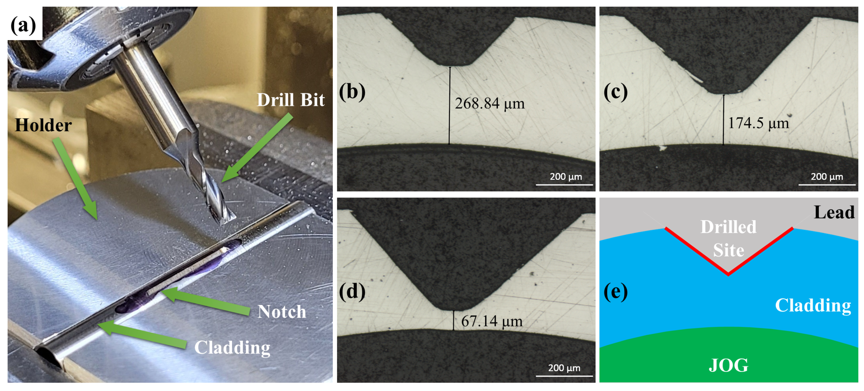
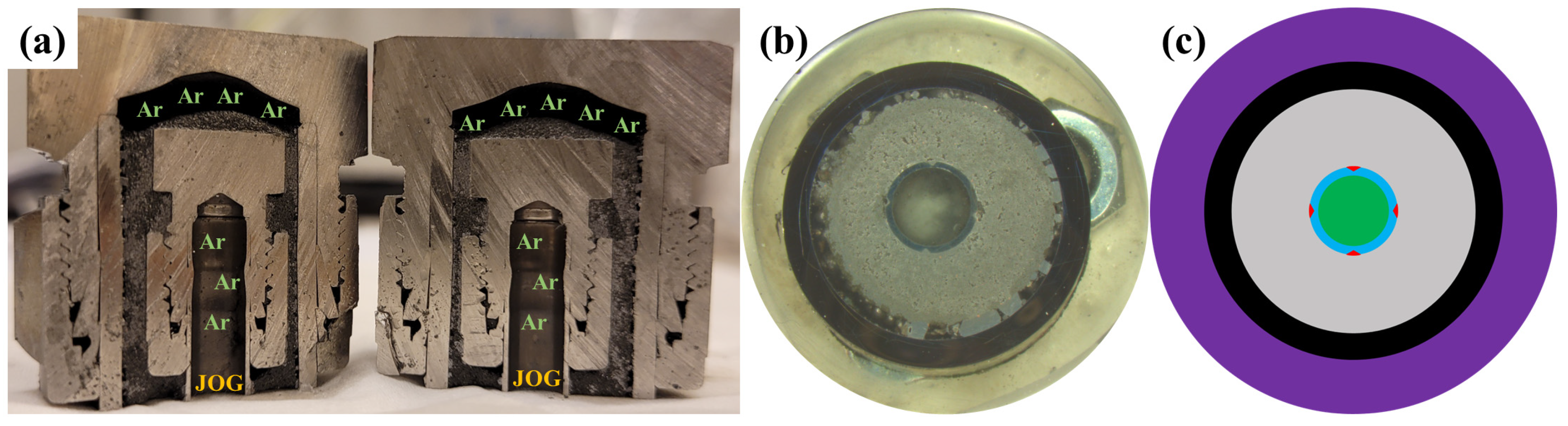
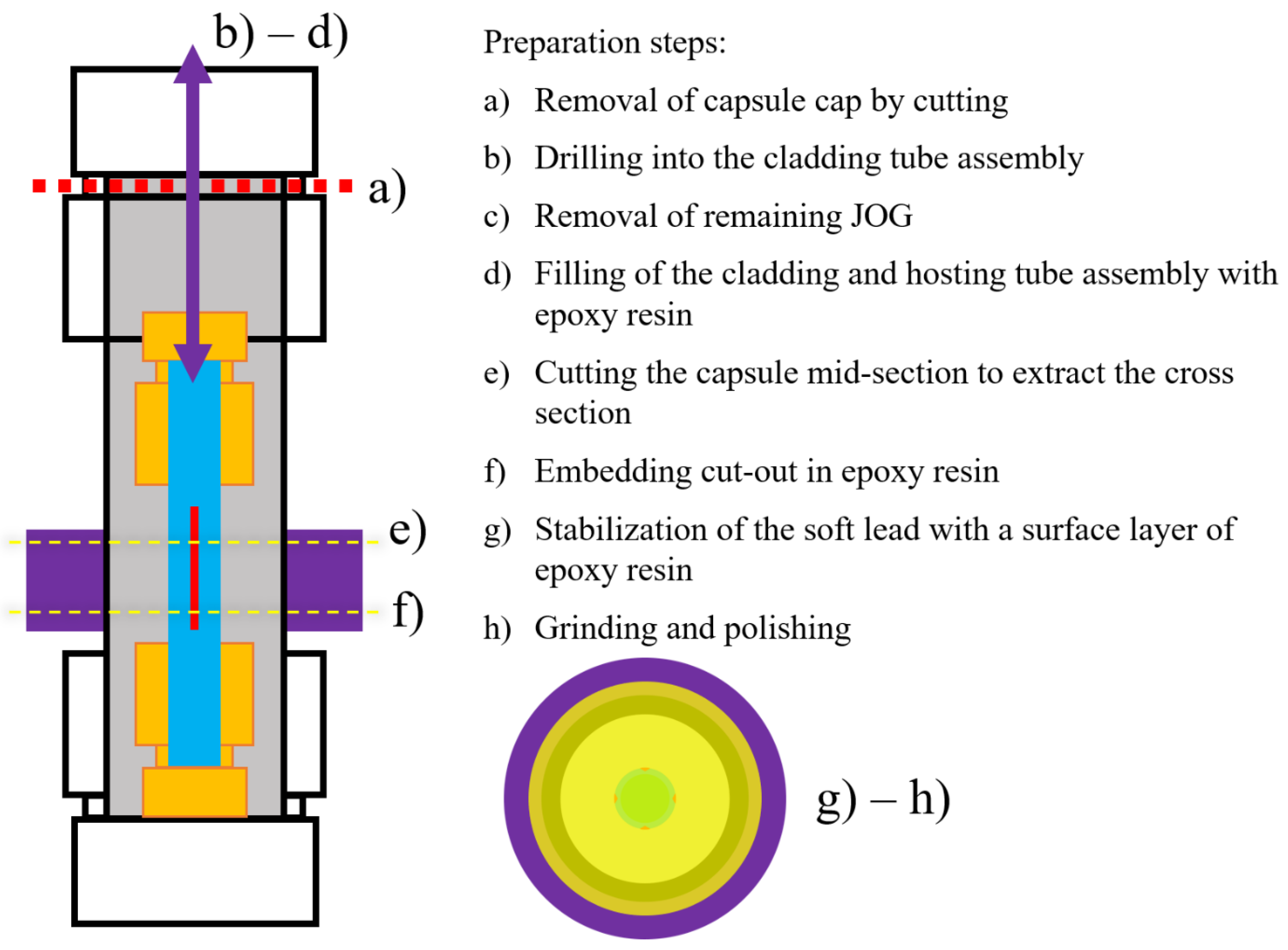
2.5. JOG Extraction and Cross-Section Preparation

After the exposures, several steps were performed to (i) extract remaining and reacted JOG from the cladding tube assembly and (ii) prepare metallographic cross-sections through the entire capsule diameter. In Figure 4, the sample preparation procedure is presented in brief.
Several considerations have been taken into account for this process: different species need to be embedded, i.e., alloys, solidified molten lead (soft), oxide scales (hard), and residue salt species at the cladding surface. Furthermore, cavities and shrinking effects are expected.
To salvage remaining JOG from the cladding interior, steps (a) and (b) were performed. After cutting off the capsule cap, a hole (Ø = 3–4 mm) was drilled through the top of the cladding tube assembly, without cooling the drill to avoid contamination. To remove the remaining JOG, the capsule was simply turned upside-down, and no additional cleaning method or chemical was used. The emptied cladding interior was then filled with epoxy resin to stabilize the surfaces for further cutting and polishing procedures. While injecting epoxy resin into the cladding tube, overflowing epoxy filled porosity and shrinkage gaps in the solidified lead between the cladding and outer capsule tube.
After embedding the capsule segment, which includes the cladding segment of interest (Figure 4e,f), the cross-section with a thickness of approximately 1.5 cm was cut via an oil-cooled high-speed saw from the lower part of the capsule. Freshly cut cross-sections were sealed once more with an epoxy resin film to fill pores and gaps between shrunken lead coolant, cladding, and capsule tube, as well air bubbles remaining after the first filling of the interior cladding tube. When the epoxy had cured again, a water-free metallographic preparation routine was performed until a 1 µm diamond polishing finish was reached. Remaining scratches and smeared areas were impossible to avoid completely due to the very soft lead smearing across the steel areas during grinding and polishing. Ethanol and acetone were used for intermittent cleaning throughout the cross-section preparation.

2.6. Characterization

For optical microscopy imaging and measurements, a Zeiss (Model: Vert.A1) optical microscope was used, as well as a Nikon SMZ800 optical microscope (coupled with “DFK NME33UX264” camera and “IC Measure” software, version 2.0.0.286, Charlotte, NC, USA). For scanning electron microscopy (SEM) and energy-dispersive X-ray spectroscopy (EDX) analysis, Phenom ProX Desktop SEM from FEI, Quanta 200 ESEM FEG from FEI, or JEOL JSM-7800F Prime were used. The images and EDX spectra were obtained using 15 kV, unless otherwise stated.

3. Results

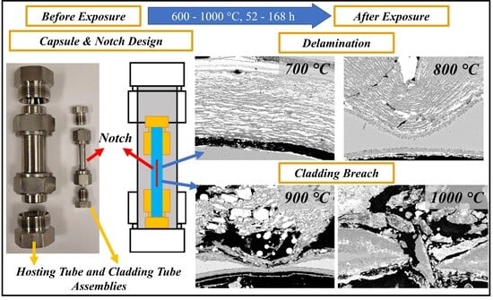
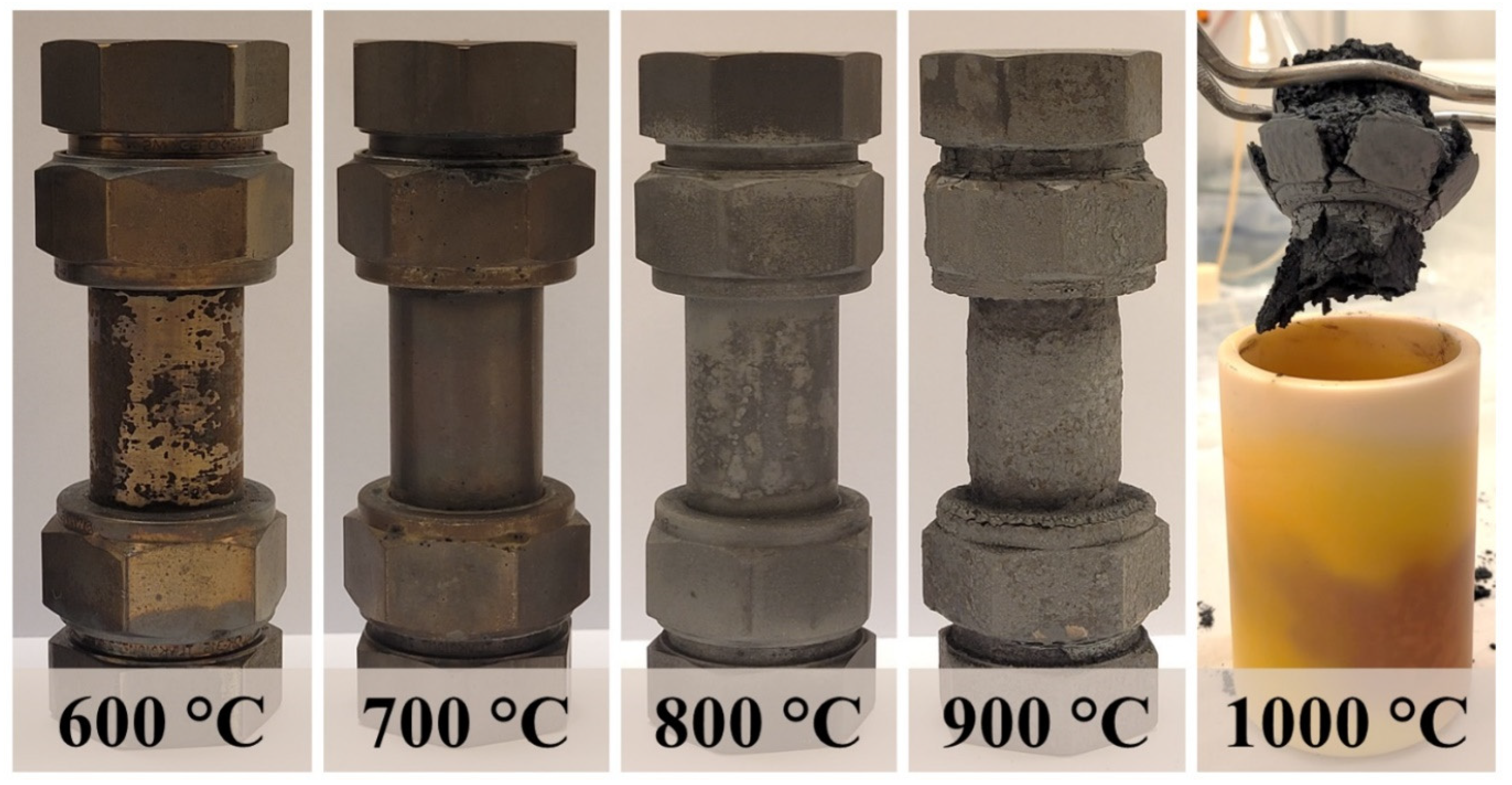
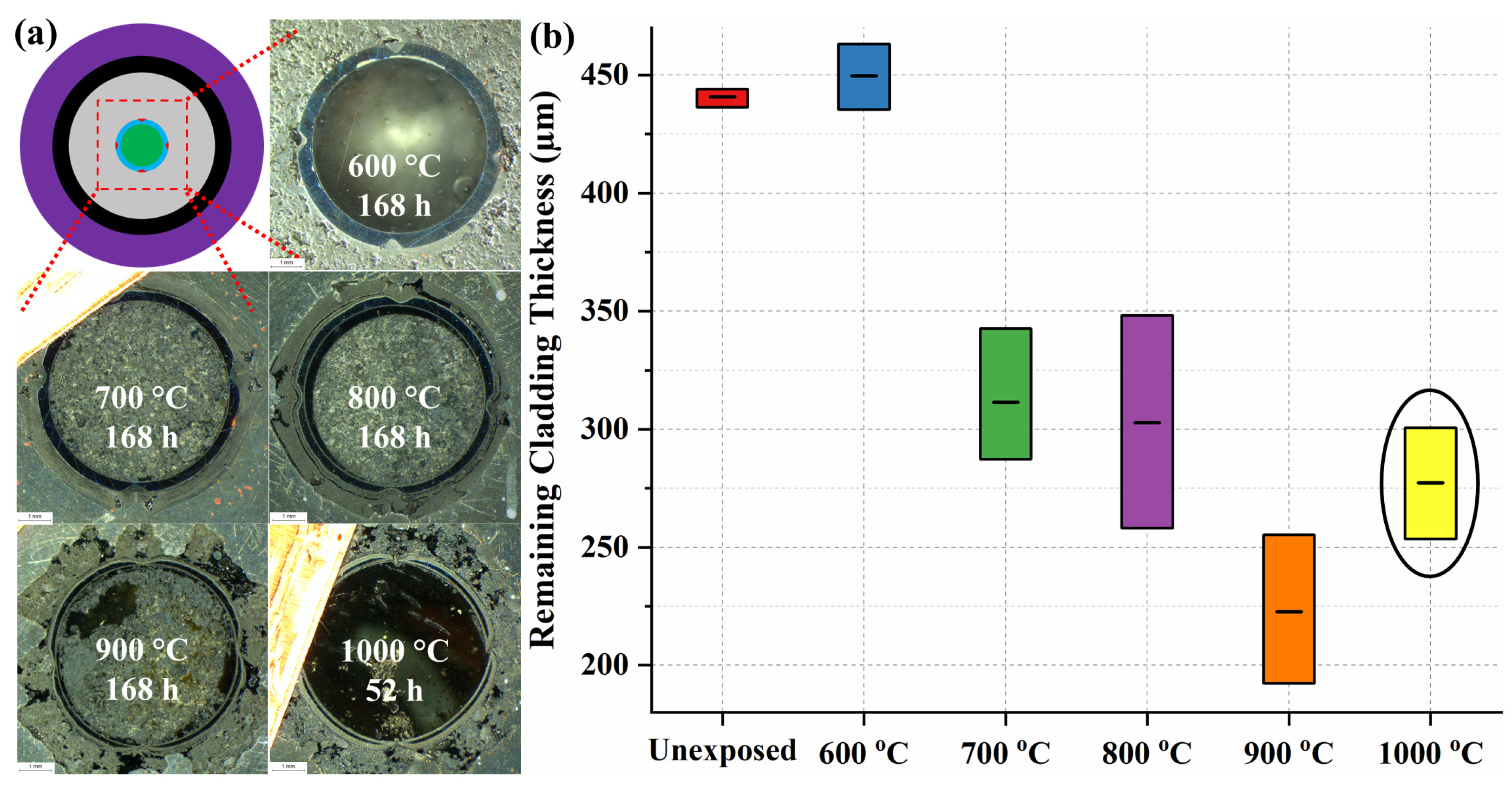
3.1. Capsule Performance

Capsules made from alloy 316 after 168 h of exposure can be seen in Figure 5. As one can easily see, the capsule changes in appearance depending on the used temperature (Figure 5). Alloy 316 oxidizes rapidly at temperatures above 800 °C [45], while 15-15Ti is optimized to reach 1000 °C. However, the hosting capsule is made from alloy 316, and suffers visually and measurably. This agrees with reported observations in the literature. Nodular oxides and thick spalling scales have been reported for these conditions [45].
The damage to the capsules increased with temperature, reaching a critical point at 1000 °C, and resulted in catastrophic failure of the capsule before 168 h had been reached; see Figure 5. The upper section of the 1000 °C exposure capsule, seen in Figure 5, was removed by hand, by applying a small amount of force. The color change around the alumina crucible indicates that it reacted with the contents of the capsule. This state of the capsule did not allow for a meaningful investigation of this experiment, and only the capsules of 600 °C to 900 °C (168 h) and 1000 °C (52 h) exposures were used for further investigation.
Cross-sections showed a decrease of the hosting tube thickness with increasing temperature, predominantly at the lead-exposed side (see Table 2). These measurements were taken by optical microscopy, taking only metallic reflective parts into account. Nonreflective oxide scales were measured separately. Measurements were taken at six individual sites, including the thickest and thinnest parts, and given as ranges.
The hosting tubes in contact with lead showed not only different scale thicknesses, but also different scale appearances with increasing temperatures. Therefore, Table 2 also presents distinguishable layers observed on the hosting tubes’ lead-exposed side. Representative figures and measurements are shown in Figure 6.

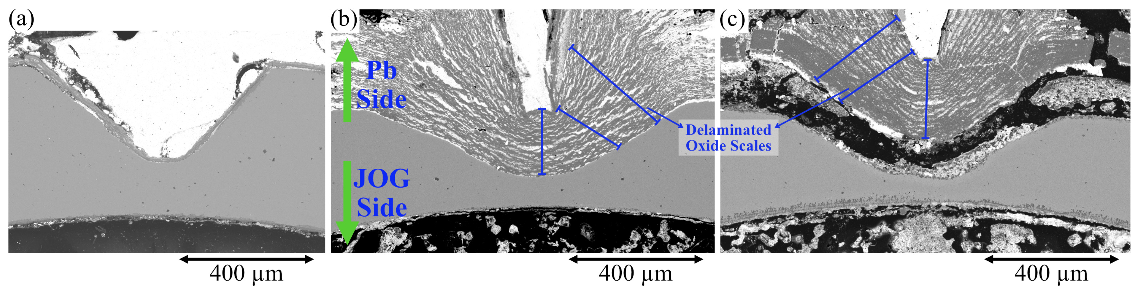
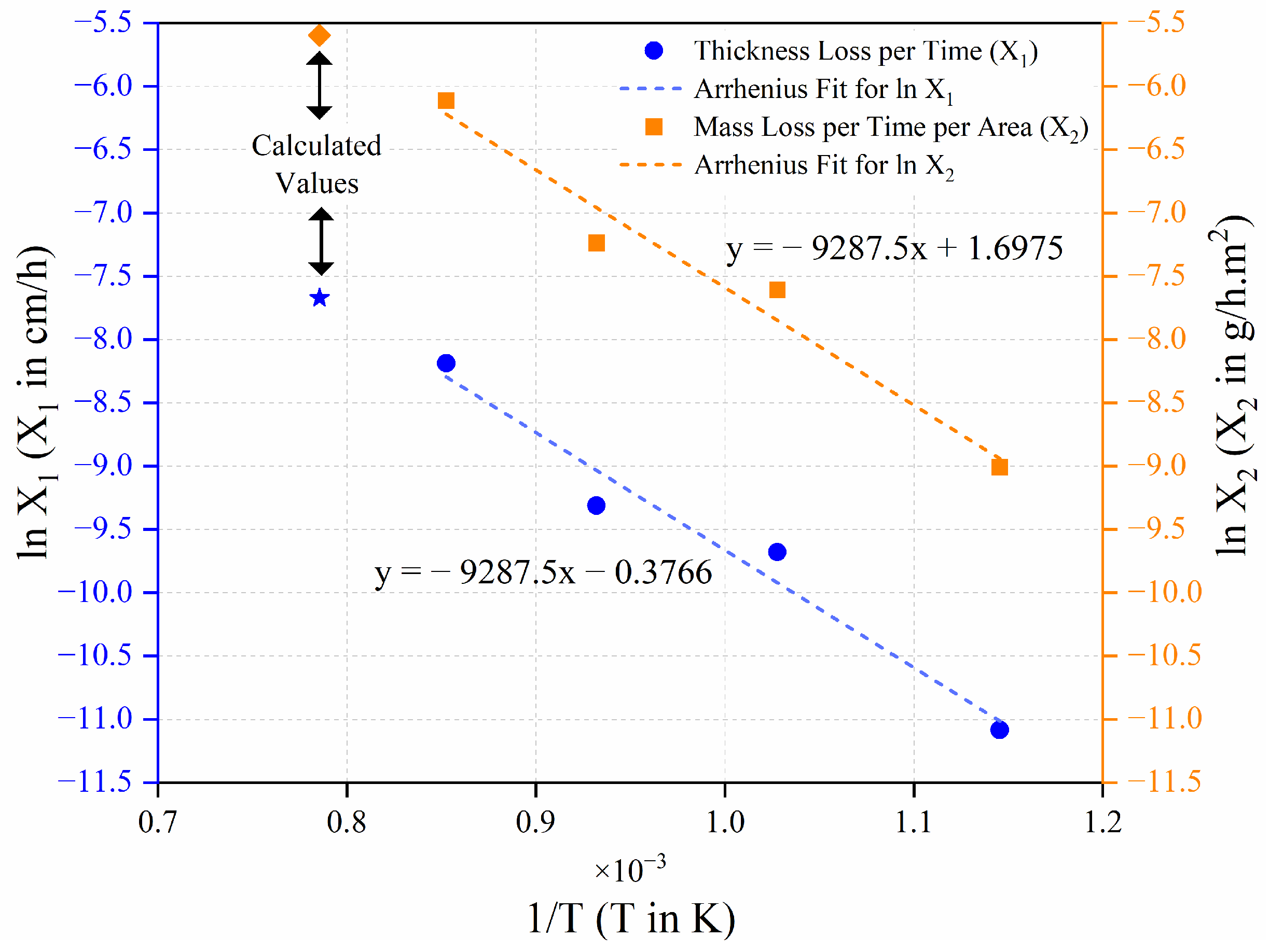
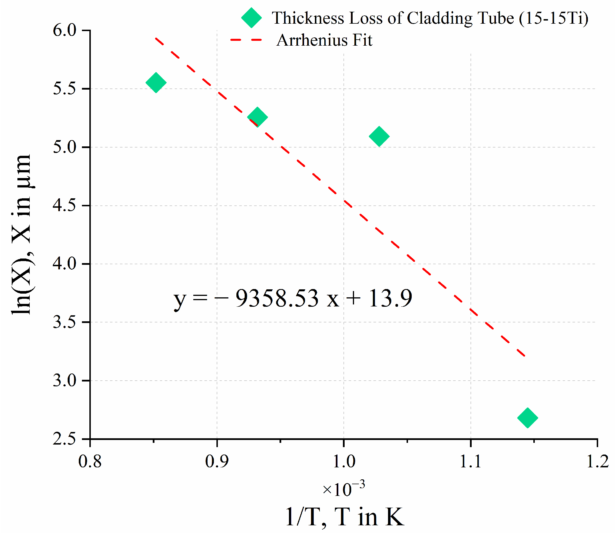
3.2. Cladding Tube Thinning Investigation

An increasing thinning of the 15-15Ti cladding tube material was observed with increasing temperature exposures of 600 °C, 700 °C, 800 °C, 900 °C (168 h), and 1000 °C (52 h). The tube thickness decreased during the exposures on both sides, one in contact with lead, the other in contact with cesium molybdate. In order to determine the extent of this thinning effect, optical microscopy images of cross-sections were taken. As the notch areas were already thinned by drilling (see Figure 2), only original tube sections were considered for wall thickness measurements. ImageJ™ open-source image (version 1.54d, USA) analysis software was used to determine the thicknesses. At least 35 thickness measurements from three different sections of the tube were used for the plot in Figure 7.
The exposure at 600 °C resulted in a small wall thickness increase. This increase might originate from the growth of corrosion layers or variations in the tube production margins. However, all other exposures resulted in significant decreases in wall thickness. At 900 °C, the remaining cladding tube wall thickness reached an average of 175 µm, less than half of the original 450 µm. Already prethinned positions, notches, were breached, which is shown later in the paper. The min/max range of thickness measurements for 800 °C and 900 °C are higher due to different local progression of corrosion fronts. A wave-like structure was observed at some of the metal–scale interfaces. The cladding material thinning at 1000 °C was reported in Figure 7 after only 52 h of exposure, since 168 h resulted in a catastrophic cladding failure (see Figure 5).

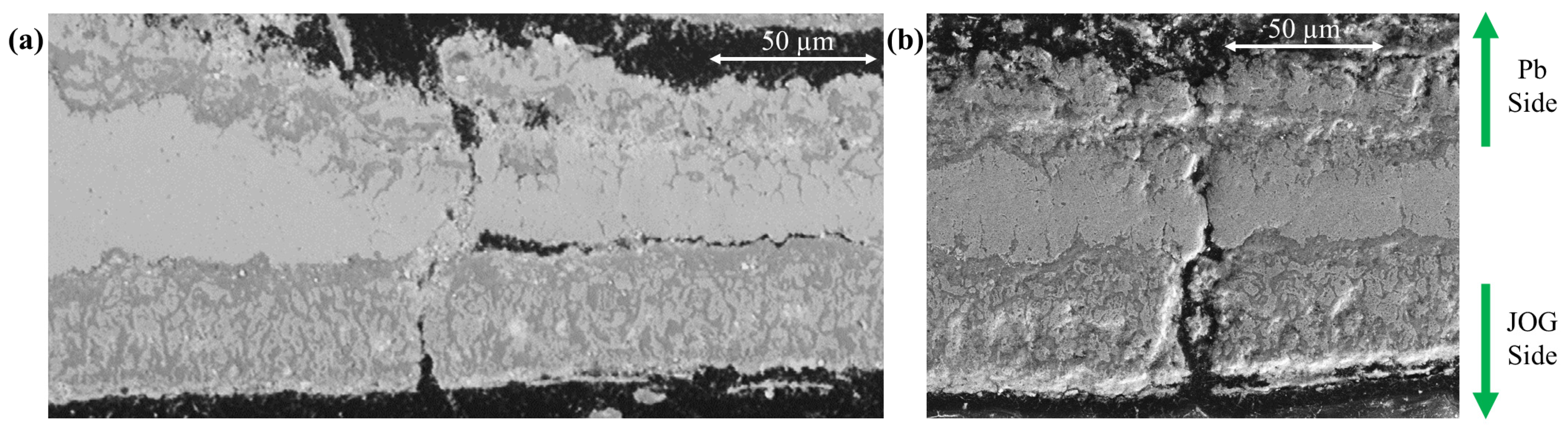
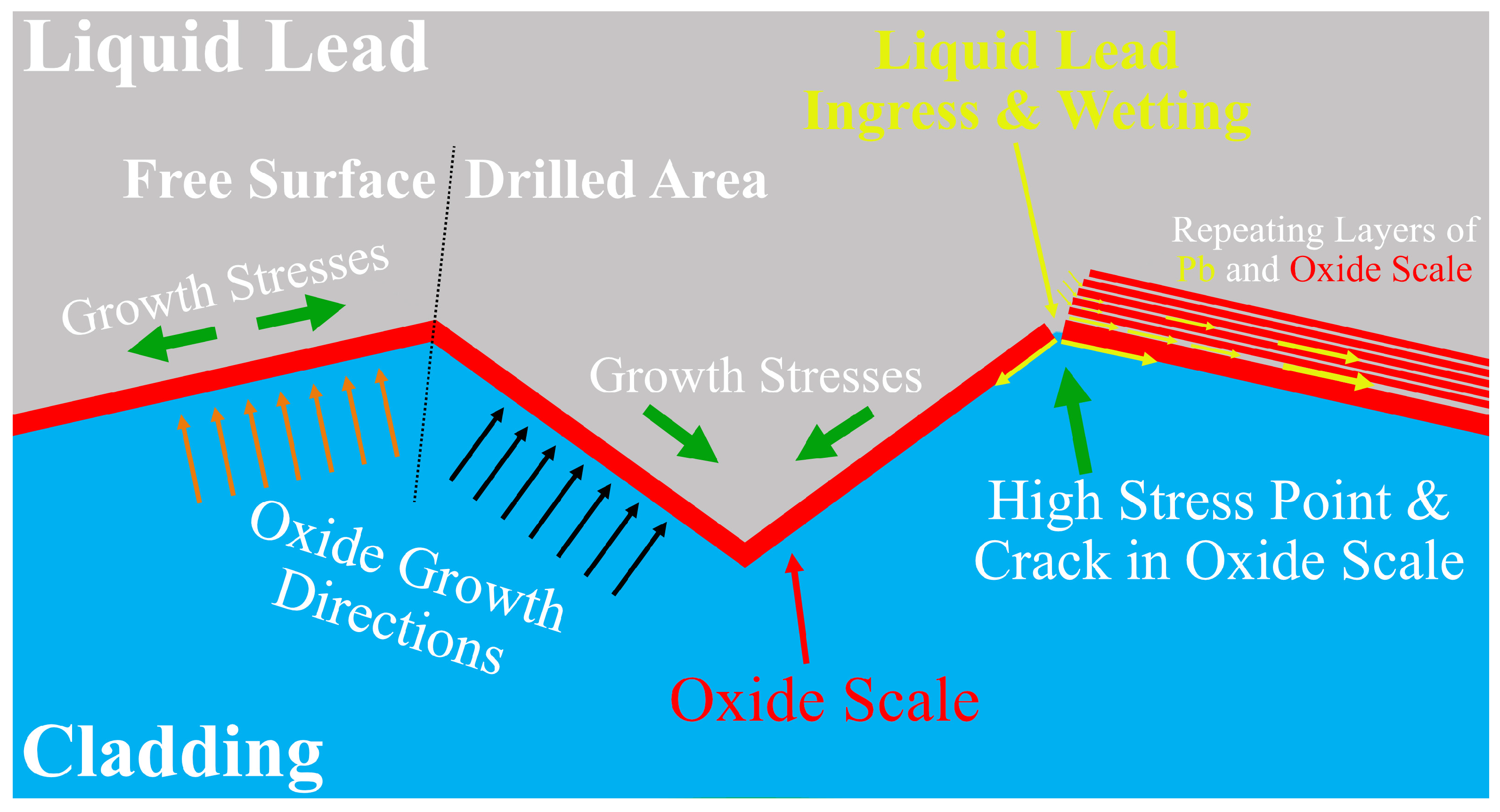
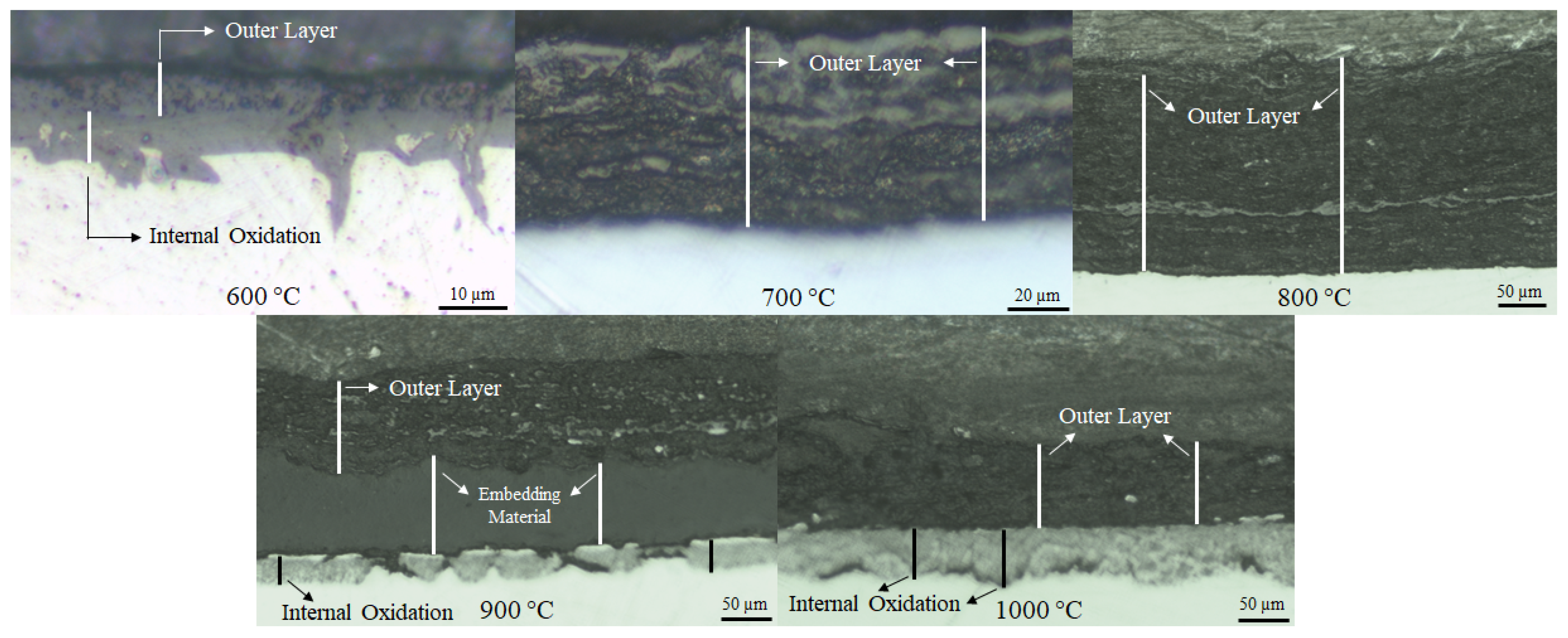
3.3. Corrosion and Breach Characteristics of the Cladding Tube

To investigate the corrosion layers and the breach characteristics in more detail, SEM analysis was performed. A cross-section segment with a notch is depicted in Figure 8 for the temperature steps of 600 °C, 700 °C, and 800 °C, after 168 h exposure. No breach was found in these cross-sections. Moreover, corrosion layers and internal oxidation from both sides had not yet reached through the material, not even in the notched areas.
While the question of Coolant–JOG interaction may not be answered by this experiment (800 °C), the evolution of corrosion processes can be observed and characterized. In the notch areas of 800 °C exposure, even though no cladding breach occurred, cesium molybdate and liquid lead came as close as 101 (±1) µm to each other. The corrosion fronts, however, were separated by only 33–45 µm intact alloy material. Here, even though JOG corrosion layers look thicker compared to the oxide scales on the Pb coolant side, detailed investigation showed that this is not the case. The corrosion layer due to JOG is homogeneous, with a consistent branch-like internal oxidation structure throughout. On the other hand, this homogeneous corrosion layer is not present on the liquid lead side of the notch. Compared to Figure 2b, the sharp edges of the notch disappear and are smoothened by the liquid lead, and oxide layers are almost absent at certain places. Elemental leaching and alloy dissolution by lead has, however, taken place and contributed to the cladding tube thinning. Moreover, a severe delamination effect was seen in 700 °C and 800 °C exposures. It should be noted that the notch area is expected to present a more heterogenous corrosion behavior compared to original tube sections. In order to correctly compare the corrosion by liquid Pb to corrosion by cesium molybdate, original tube sections (outside of notched areas) were investigated. Figure 9 shows a more detailed view of a more homogenous lead corrosion layer on an original tube section for the cladding exposed to 800 °C.
Here, the corrosion layer caused by contact of 15-15Ti with liquid lead occurs with a more homogenous thickness, unlike the predrilled area of the same exposure (Figure 8c). However, on the JOG-side, the layers are almost identical to the ones observed in Figure 8c. As the drilling was performed on the lead-side and not on the JOG-side, it is possible to describe the effect of drilling on the notches. The mechanically treated notches exhibit a more heterogeneous behavior due to microstructural deformation, chipping, and roughness, while their unaffected counterparts (original tube sections) form more continuous layers.
The investigation of original tube sections allows for a more accurate study of each corrosive reactant’s contribution to the cladding breach scenario. From the cross-section in Figure 9, the average thicknesses of lead and JOG corrosion layers were measured to be 27 µm and 32 µm, respectively. In contrary to the notch area shown in Figure 8c, at 800 °C, corrosion from both sides of the cladding tube have similar contributions to a possible cladding breach.
Increasing the temperature further, it is expected that the ratio between both environments’ contributions to scale growth and alloy dissolution changes additionally when approaching the melting temperature of cesium molybdate at ~950 °C [48].
The cladding tube exposed to 900 °C suffered multiple cladding breaches at the prethinned notch sites. The breaches were documented by optical microscopy and SEM imaging; the line fractures can be seen Figure 10. On the JOG-side, the internal corrosion species have a branch-like structure comparable to those observed after the exposure at 800 °C (Figure 9), but certainly more extensive at 900 °C. These “branches” are a crucial part of the corrosion process due to their possible role in material coherence loss and consequent cladding breach. In both images of Figure 10, JOG-side corrosion layers can be clearly observed. Within the internal corrosion layer, branches growing vertical to the metal–scale interface facilitate short-circuiting between both environments. The breach observed after 168 h at 900 °C did not cause observable mass transport between the two environments, liquid lead and JOG.
This, however, was the case after the 52 h exposure at 1000 °C, which suffered from comparatively broad cladding breaches, and even notch consumption. Optical microscopy was sufficient to confirm the cladding failure of at least three notches in the investigated cross-section. In Figure 11, the breakthroughs from the notches clearly show that lead has pressed inwards, from the outer coolant side into the cladding tube JOG environment. Interestingly, in the immediate outer side of the cladding, a discoloration of the lead can be observed. This indicates an interaction of cesium molybdate and liquid lead.
Figure 12 shows the gradual consumption of two of the notch areas where the cladding failure occurred. The center of the notches was already completely consumed, and only fragments were extruded on the JOG side in Figure 12a. Four distinct layers can be observed: (from JOG to lead side) corrosion layer caused by cesium molybdate, the remaining cladding itself, and the double oxide layer caused by oxygen transported in liquid lead. As the cladding becomes thinner closer to the breach area (or the center of notch), the inner part of the double oxide layer disappears, while the outer part of the double oxide layer becomes the dominant corrosion layer at the scale–lead interface.
Figure 12a allows for the conclusion that the stress from the liquid lead side was sufficient to push through the thin cladding remnant inwards into the tube, and thereby higher than inside the cladding tube, on the JOG side.

4. Discussion

The capsule integrity has been a crucial part of this study besides the cladding itself, since it consists of alloy 316, which is not vastly different from alloy 15-15Ti. Due to lead’s vapor pressure at the LFR accident conditions, a leak is undesirable. The temperature limit of the exposure capsule was established to be between 900 °C and 1000 °C as the capsule fully oxidized and swelled three times its size at 1000 °C, after 168 h exposure. The visual inspection of the capsules exposed at 600–900 °C does not indicate a structural failure, but the durability of exposures above 800 °C is questionable beyond 168 h. The current exposure duration is one week, which is too long of a timeframe to consider for an accident scenario. It is unlikely that this type of overheating would not be countered by emergency measures. The derived data here presents a prolonged overheating period. The nominal operational temperature of the reactor hot zones is on the order of ≈500 °C, 100 °C lower than the lowest experimental conditions of this study.
The main body of the capsule is composed of the hosting tube and its respective caps. Due to the thickness and complexity of the caps, the hosting tube stands out as the weak link in the structural integrity of the capsule. In particular, the assembly point of Swagelok™ caps with the hosting tube would be the weakest point, as it is under tension due to the assembly of the hosting tube and its respective caps. As such, additional attention was given to the investigation of the corrosion on the hosting tube, which is in contact with the same liquid lead as the cladding tube. Optical microscopy revealed that the hosting tubes suffered a loss in their thicknesses, which was brought into kinetic context. In Table 2, the remaining tube thicknesses are listed, with differences to the original 2 mm. An Arrhenius approach was used, and the rate constant “ k ” was hereby used in form of the thickness loss “X”. The original Arrhenius Equation (1), where E A is the activation energy, T is the temperature in Kelvin, R is the gas constant ( 8.314   J / m o l . K ), and A is the pre-exponential factor, was thereby used instead, as stated in Equation (2), treating the activation energy term as constant C ln X was plotted against 1 / T and trendlines were fitted to obtain fitting values ( R 2 ) in Figure 13.
ln k = E A R × 1 T + ln A
ln X = C × 1 T + ln A
Only 168 h exposures were used as data points. Left y-axis (blue) shows the logarithm of thickness loss X normalized against time; as opposed to 168 h, right y-axis (orange) instead shows the loss of material as normalized to per area, and converted to grams per volume. Here the density was taken as given in Swagelok™ catalogs [49]. The plot shows that thickness loss on the hosting tube is a good fit into the Arrhenius equation to explain the relationship between temperature and material loss. This relationship can be used as an approximation into the behavior of reactor vessels under elevated temperature conditions. Although the fittings are good, the calculated value (0.78 mm per 168 h) for 1000 °C (168 h) exposure does not explain the catastrophic failure observed in Figure 5. This inconsistency can be explained by the fact that our Arrhenius approach only accounts for the chemical reactions, and does not consider mechanical stresses on the capsule. Particularly, the assembly areas between hosting tube and its caps have been discussed before. An accelerated corrosion of this area can cause a failure earlier than the chemically predicted point, causing the whole capsule to fail catastrophically. These are in addition to the reported corrosion behavior of alloy 316 in high temperature air, which the hosting tube was subjected to from outside [45,46].
Corrosion layers shown in Figure 6 are accounted for as lost material in Arrhenius plots. For the transition from 600 °C to 700 °C, the internal oxidation disappeared, and heterogeneous lamellar outer oxide scales have been observed. Similar to the total thickness loss, higher temperature exposures show a higher range of layer thickness, meaning a more heterogeneous behavior. In the case of reactor operation; this heterogenous behavior is expected to make in-pile measurements more difficult, and possibly even unreliable in some cases. As such, the maximum and minimum values become more important. Internal oxidation increases again at temperatures ≥ 900 °C. The stability and diffusion kinetics of the oxide layers formed on the outer rim would directly affect these internal layers. The higher temperature allowed oxygen to diffuse faster; however, the information regarding leached-out metallic components requires a more detailed chemical analysis.
The cladding tube thinning is a more complicated process compared to hosting tube thinning. Cladding tubes were exposed to a dual environment corrosion process where liquid lead and cesium molybdate were acting together from opposite sides of the cladding. On the lead side, repeated delamination was observed, as seen in Figure 8. This effect occurred more severely on exposures ≥ 700 °C. Brittle oxide scales cracked on accumulated crack growth sites corresponding to concave/convex transition points present at drilled sites. Cracks allow lead to ingress and wet the surfaces underneath. Due to temperature differences, this phenomenon was much more aggressive on exposures ≥ 700 °C, where cracking and wetting happened repeatedly, causing multiple layers to form and delaminate (as observed on Figure 8). A schematic for this phenomenon can be seen in Figure 14. The delamination was identified as the main cause for cladding material loss, and occurred only on the lead side.
The corrosive nature of the reactants actually increased the thickness for 600 °C exposure at some locations. For consistency, the minimum thickness values were used instead in Table 3, and Equation (3) was formulated as a result. The exposure at 900 °C has a wide range of thickness (close to ±100 µm on some spots), bringing the corrosion process into a heterogeneous context. The severity of the thinning increased with temperature, as expected. Even though the differences between loss of thickness between 800 °C (168 h) and 1000 °C (52 h) are similar, 1000 °C has less discrepancy between its maximum and minimum value. This indicates that the heterogeneous thinning would be a result of long exposure. Using these datapoints with all their inherent insecurities, one arrives at a surprisingly well-fitting temperature at which total consumption of the cladding tube would be expected after 168 h (Table 3, with its visualization in Figure 15).
ln X = 9358.53 × 1 T + 13.9
In this set of experiments, only the exposures at 900 °C (168 h) and 1000 °C (52 h) suffered breaches. The thinning correlates with the cladding breaches, as the leftover thickness on drilled sites would have to be consumed by the corrosive species. The data from original tube sections can be used to approximate the behavior on notch sites. However, microstructural deformation from the drilling and shape of the notch crater alters the corrosion scales growing on the lead side, while the JOG side is not affected. The branch-like structure of the observed internal oxidation that can be seen after exposure at 800 °C on the lead side is also seen at higher temperatures, causing breach initiation.
The described corrosion observations become even more pronounced when discussing them in correlation to reactor operation conditions and tensile load on the fuel pins. Over a fuel pin lifetime, the harsh chemical environment would have the addition of a 100 to 150 dpa (displacement per atom) irradiation field, mainly caused by neutron irradiation [11,50]. Particularly in this study, our assumption considers a high burn-up situation where the residence time for the cladding would be long, and even nearing its end of service, thereby also reaching the highest accumulation of JOG species caused by burn-up.
Therefore, we consider the performance of the original cladding material with unaffected microstructure and a total thickness of 450 µm too optimistic for an accident situation with high JOG impact. The more conservative approximation of a highly predamaged material simulated by the loss of two thirds of its thickness, such as shown for notch locations, is a more appropriate accident approach.
Even though the irradiation effect on corrosion was not experimentally investigated here, the cladding corrosion must be discussed with relation to irradiation when a high burn-up situation is assumed. The comparison of JOG-side corrosion between Figure 9 and Figure 10, i.e., between corrosion features after exposure at 800 °C and 900 °C, shows a clear correlation of internal oxidation depth, reaching into the cladding perpendicular to the surface and temperature. Corrosion studies on irradiated austenitic materials have reported that the dislocation movement is enhanced as the dpa value increases [51]. High burn-up product concentrations as said JOG correlates with high dpa values, accelerating corrosion processes.
The details of breach progression need to be confirmed with more extensive temperature-dependent chemical analysis of the corrosion products, which is the scope of the upcoming second part of this publication.
It is gratifying at this stage of the study to confirm that operating a Gen-IV reactor at 500 °C is a reasonable temperature maximum. Furthermore, our data and derived trendlines can be utilized to acquire a risk assessment for short time overheating of the reactor coolant, lead.

5. Conclusions

A new capsule design and evaluation was completed to investigate the interaction between liquid lead, fuel cladding (Sandvik 15-15Ti steel), and JOG phases at accident conditions (T ≥ 600 °C).
The capsule integrity was evaluated between 600 °C and 900 °C, for 168 h, and at 1000 °C for 52 h.
Notches on fuel cladding were used successfully to shorten the time to failure and observe a controlled breach of fuel claddings. The notch geometry was verified by pre-exposure sample cross-sections.
A metallographic sample preparation process was drawn up to reveal and investigate the corrosion progress for the cladding and hosting tubes.
Limits of the capsule performance were rendered by observing hosting tube failure. The thinning effect showed a degradation that fits well with Arrhenius plots of temperature-dependent material consumption.
At the original tube sections of the cladding tube (non-notched surfaces), it was observed that the thickness of the cladding tube had changed during exposure. While the thickness increased 2% at 600 °C, a thinning effect was observed on the rest of the exposures. The thinning of the cladding tube wall exposed to 700 °C and 800 °C after 168 h was noticeable but not severe. However, the thinning observed after exposures at 900 °C and 1000 °C was severe enough to cause a breach on the notches.
Both liquid lead and cesium molybdate had similar contributions to cladding breaches as corrosive reactants.
Delamination by liquid lead was identified as one of the main causes of thinning. This phenomenon was more apparent in exposures ≥ 700 °C. The intersection of free surfaces and drilled areas was the most susceptible to liquid lead wetting and subsequent delamination, especially at 600 °C.
At 900 °C, internal oxidation from both lead coolant- and JOG-side caused line fractures.
At 1000 °C, after only 52 h, the most severe cladding breach occurred. Here, the Pb corrosion formed a double oxide scale on the coolant side, which progressed faster compared to JOG-induced corrosion.
Extrapolating the cladding consumption data for 600 °C to 900 °C in an Arrhenius plot forecasts a total cladding consumption (450 µm) after 168 h between 900 °C and 1000 °C, as has also been observed.
The effects of irradiation were not tested experimentally, but considered when discussing the results. As atom displacement is enhanced by irradiation, corrosion attack is likely to propagate faster. To illustrate an enhanced integrity loss, a highly predamaged material was used, simulated by the loss of two thirds of its thickness in notch locations. Creep effects were not considered or examined in this study, as the cladding sample is not under any external mechanical load.
This dataset can be used for risk assessments for short term overheated lead coolant in contact with 15-15Ti cladding.

Author Contributions

Conceptualization, D.T., T.R.V. and C.G.; methodology, D.T., T.R.V. and C.G.; formal analysis, D.T. and C.G.; investigation, D.T.; writing—original draft preparation, D.T.; writing—review and editing, D.T., T.R.V. and C.G.; visualization, D.T.; supervision, T.R.V. and C.G.; funding acquisition, T.R.V. All authors have read and agreed to the published version of the manuscript.

Funding

The authors would like to thank the European Commission and Euratom for funding the PASCAL project (Grant Agreement ID: 945341).

Data Availability Statement

The data presented in this study are available on request from the corresponding author.

Acknowledgments

The authors would like to thank Anna Louise Smith and Andries van Hattem, from Delft University of Technology, for their advice on procurement and handling of JOG compounds. This work was performed in part at the Chalmers Material Analysis Laboratory, CMAL.

Conflicts of Interest

The authors declare no financial or commercial conflict of interest.

References

  1. Kelly, J.E. Generation IV International Forum: A decade of progress through international cooperation. Prog. Nucl. Energy 2014, 77, 240–246. [Google Scholar] [CrossRef]
  2. Murty, K.L.; Charit, I. Structural materials for Gen-IV nuclear reactors: Challenges and opportunities. J. Nucl. Mater. 2008, 383, 189–195. [Google Scholar] [CrossRef]
  3. Fazio, C.; Sobolev, V.; Aerts, A.; Gavrilov, S.; Lambrinou, K.; Schuurmans, P.; Gessi, A.; Agostini, P.; Ciampichetti, A.; Martinelli, L. Handbook on Lead-Bismuth Eutectic Alloy and Lead Properties, Materials Compatibility, Thermal-Hydraulics and Technologies; Organisation for Economic Co-Operation and Development: Paris, France, 2015. [Google Scholar]
  4. Roy, M.; Martinelli, L.; Ginestar, K.; Favergeon, J.; Moulin, G. Dissolution and oxidation behaviour of various austenitic steels and Ni rich alloys in lead-bismuth eutectic at 520 °C. J. Nucl. Mater. 2016, 468, 153–163. [Google Scholar] [CrossRef]
  5. Buckthorpe, D. Introduction to Generation IV nuclear reactors. In Structural Materials for Generation IV Nuclear Reactors; Elsevier: Amsterdam, The Netherlands, 2017; pp. 1–22. [Google Scholar]
  6. Alemberti, A.; Caramello, M.; Frignani, M.; Grasso, G.; Merli, F.; Morresi, G.; Tarantino, M. ALFRED reactor coolant system design. Nucl. Eng. Des. 2020, 370, 110884. [Google Scholar] [CrossRef]
  7. Abderrahim, H.A.; Baeten, P.; De Bruyn, D.; Heyse, J.; Schuurmans, P.; Wagemans, J. MYRRHA, a Multipurpose hYbrid Research Reactor for High-end Applications. Nucl. Phys. News 2010, 20, 24–28. [Google Scholar] [CrossRef]
  8. Delville, R.; Stergar, E.; Verwerft, M. Results of a New Production of Nuclear-Grade 1.4970 ‘15-15Ti’Stainless Steel Fuel Cladding Tubes for GEN IV Reactors. In Proceedings of the International Conference on Nuclear Engineering, Prague, Czech Republic, 7–11 July 2014. [Google Scholar]
  9. Kautz, E.; Gwalani, B.; Yu, Z.; Varga, T.; Geelhood, K.; Devaraj, A.; Senor, D. Investigating zirconium alloy corrosion with advanced experimental techniques: A review. J. Nucl. Mater. 2023, 585, 154586. [Google Scholar] [CrossRef]
  10. Henry, J.; Maloy, S.A. Irradiation-resistant ferritic and martensitic steels as core materials for Generation IV nuclear reactors. In Structural Materials for Generation IV Nuclear Reactors; Elsevier: Amsterdam, The Netherlands, 2017; pp. 329–355. [Google Scholar]
  11. Séran, J.L.; Le Flem, M. Irradiation-resistant austenitic steels as core materials for Generation IV nuclear reactors. In Structural Materials for Generation IV Nuclear Reactors; Elsevier: Amsterdam, The Netherlands, 2017; pp. 285–328. [Google Scholar]
  12. Frazer, D.; Qvist, S.; Parker, S.; Krumwiede, D.L.; Caro, M.; Tesmer, J.; Maloy, S.A.; Wang, Y.Q.; Hosemann, P. Degradation of HT9 under simultaneous ion beam irradiation and liquid metal corrosion. J. Nucl. Mater. 2016, 479, 382–389. [Google Scholar] [CrossRef]
  13. Uwaba, T.; Ito, M.; Maeda, K. Diametral strain of fast reactor MOX fuel pins with austenitic stainless steel cladding irradiated to high burnup. J. Nucl. Mater. 2011, 416, 350–357. [Google Scholar] [CrossRef]
  14. Maeda, K.; Asaga, T. Change of fuel-to-cladding gap width with the burn-up in FBR MOX fuel irradiated to high burn-up. J. Nucl. Mater. 2004, 327, 1–10. [Google Scholar] [CrossRef]
  15. Barani, T.; Pizzocri, D.; Cappia, F.; Luzzi, L.; Pastore, G.; Van Uffelen, P. Modeling high burnup structure in oxide fuels for application to fuel performance codes. part I: High burnup structure formation. J. Nucl. Mater. 2020, 539, 152296. [Google Scholar] [CrossRef]
  16. Yurechko, M.; Schroer, C.; Skrypnik, A.; Wedemeyer, O.; Tsisar, V.; Konys, J. Steel T91 subjected to static stress in lead-bismuth eutectic at 450–550 °C and low oxygen concentration. J. Nucl. Mater. 2018, 512, 423–439. [Google Scholar] [CrossRef]
  17. Ejenstam, J.; Halvarsson, M.; Weidow, J.; Jönsson, B.; Szakalos, P. Oxidation studies of Fe10CrAl–RE alloys exposed to Pb at 550 °C for 10,000 h. J. Nucl. Mater. 2013, 443, 161–170. [Google Scholar] [CrossRef]
  18. Hojna, A.; Di Gabriele, F.; Klecka, J. Characteristics and Liquid Metal Embrittlement of the steel T91 in contact with Lead-Bismuth Eutectic. J. Nucl. Mater. 2016, 472, 163–170. [Google Scholar] [CrossRef]
  19. Schroer, C.; Voss, Z.; Wedemeyer, O.; Novotny, J.; Konys, J. Oxidation of steel T91 in flowing lead-bismuth eutectic (LBE) at 550 °C. J. Nucl. Mater. 2006, 356, 189–197. [Google Scholar] [CrossRef]
  20. Polekhina, N.A.; Litovchenko, I.Y.; Almaeva, K.V.; Pinzhin, Y.P.; Akkuzin, S.A.; Tyumentsev, A.N.; Chernov, V.M.; Leontyeva-Smirnova, M.V. Behavior of 12% Cr low-activation ferritic-martensitic steel EK-181 after holding in a static lead melt at 600 °C for 3000 hours. J. Nucl. Mater. 2021, 545, 152754. [Google Scholar] [CrossRef]
  21. Lambrinou, K.; Charalampopoulou, E.; Van der Donck, T.; Delville, R.; Schryvers, N. Corrigendum to “Dissolution corrosion of 316L austenitic stainless steels in contact with static liquid lead-bismuth eutectic (LBE) at 500 °C”. Nucl. Mater. 2017, 490, 9–27. J. Nucl. Mater. 2017, 490, 345. [Google Scholar] [CrossRef]
  22. Schroer, C.; Wedemeyer, O.; Novotny, J.; Skrypnik, A.; Konys, J. Selective leaching of nickel and chromium from Type 316 austenitic steel in oxygen-containing lead–bismuth eutectic (LBE). Corros. Sci. 2014, 84, 113–124. [Google Scholar] [CrossRef]
  23. Glasbrenner, H.; Konys, J.; Mueller, G.; Rusanov, A. Corrosion investigations of steels in flowing lead at 400 °C and 550 °C. J. Nucl. Mater. 2001, 296, 237–242. [Google Scholar] [CrossRef]
  24. Košek, L.; Rozumová, L.; Hojná, A.; Aparicio, C.; Vronka, M.; Vít, J. Mechanism of localized corrosion issues of austenitic steels exposed to flowing lead with 10−7 wt.% oxygen at 480 °C up to 16,000 h. J. Nucl. Mater. 2022, 572, 154045. [Google Scholar] [CrossRef]
  25. Vogt, J.-B.; Proriol Serre, I. A Review of the Surface Modifications for Corrosion Mitigation of Steels in Lead and LBE. Coatings 2021, 11, 53. [Google Scholar] [CrossRef]
  26. Cautaerts, N.; Delville, R.; Dietz, W.; Verwerft, M. Thermal creep properties of Ti-stabilized DIN 1.4970 (15-15Ti) austenitic stainless steel pressurized cladding tubes. J. Nucl. Mater. 2017, 493, 154–167. [Google Scholar] [CrossRef]
  27. Zhang, J.S.; Li, N. Review of the studies on fundamental issues in LBE corrosion. J. Nucl. Mater. 2008, 373, 351–377. [Google Scholar] [CrossRef]
  28. Bassini, S.; Antonelli, A.; Di Piazza, I.; Tarantino, M. Oxygen sensors for Heavy Liquid Metal coolants: Calibration and assessment of the minimum reading temperature. J. Nucl. Mater. 2017, 486, 197–205. [Google Scholar] [CrossRef]
  29. Rosseel, K.; Lim, J.; Marino, A.; Gladinez, K.; Gonzalez-Prieto, B.; Aerts, A. HELIOS3: A stirred bubble column for oxygen addition or reduction in lead-bismuth eutectic. Nucl. Eng. Des. 2020, 365, 110716. [Google Scholar] [CrossRef]
  30. Ni-Pb Binary Phase Diagram 0–100 at.% Pb: Datasheet from “PAULING FILE Multinaries Edition—2022”. SpringerMaterials. Available online: https://materials.springer.com/isp/phase-diagram/docs/c_0905795 (accessed on 24 April 2023).
  31. Klecka, J.; Di Gabriele, F.; Hojna, A. Mechanical properties of the steel T91 in contact with lead. Nucl. Eng. Des. 2015, 283, 131–138. [Google Scholar] [CrossRef]
  32. Cr-Pb Binary Phase Diagram 0–100 at.% Pb: Datasheet from “PAULING FILE Multinaries Edition—2022”. SpringerMaterials. Available online: https://materials.springer.com/isp/phase-diagram/docs/c_0900789 (accessed on 24 April 2023).
  33. Müller, G.; Schumacher, G.; Zimmermann, F. Investigation on oxygen controlled liquid lead corrosion of surface treated steels. J. Nucl. Mater. 2000, 278, 85–95. [Google Scholar] [CrossRef]
  34. Weisenburger, A.; Schroer, C.; Jianu, A.; Heinzel, A.; Konys, J.; Steiner, H.; Muller, G.; Fazio, C.; Gessi, A.; Babayan, S.; et al. Long term corrosion on T91 and AISI1 316L steel in flowing lead alloy and corrosion protection barrier development: Experiments and models. J. Nucl. Mater. 2011, 415, 260–269. [Google Scholar] [CrossRef]
  35. Fazio, C.; Balbaud, F. Corrosion phenomena induced by liquid metals in Generation IV reactors. In Structural Materials for Generation IV Nuclear Reactors; Elsevier: Amsterdam, The Netherlands, 2017; pp. 23–74. [Google Scholar]
  36. Maeda, K.; Tanaka, K.; Asaga, T.; Furuya, H. Distributions of volatile fission products in or near the fuel-cladding gap of the FBR MOX fuel pins irradiated to high burn-up. J. Nucl. Mater. 2005, 344, 274–280. [Google Scholar] [CrossRef]
  37. Haste, T.; Payot, F.; Bottomley, P.D.W. Transport and deposition in the Phebus FP circuit. Ann. Nucl. Energy 2013, 61, 102–121. [Google Scholar] [CrossRef]
  38. Tourasse, M.; Boidron, M.; Pasquet, B. Fission product behaviour in phenix fuel pins at high burnup. J. Nucl. Mater. 1992, 188, 49–57. [Google Scholar] [CrossRef]
  39. Imoto, S. Chemical-State of Fission-Products in Irradiated UO2. J. Nucl. Mater. 1986, 140, 19–27. [Google Scholar] [CrossRef]
  40. Wallez, G.; Raison, P.E.; Smith, A.L.; Clavier, N.; Dacheux, N. High-temperature behavior of dicesium molybdate Cs2MoO4: Implications for fast neutron reactors. J. Solid State Chem. 2014, 215, 225–230. [Google Scholar] [CrossRef]
  41. Smith, A.L.; Vlieland, J.; Pignié, M.C.; Abbink, M.; Mikaelian, G.; Benigni, P. New insights into the Cs-Mo-O system: Experimental studies of the Cs2MoO4-MoO3 pseudo-binary system. Thermochim. Acta 2021, 696, 178825. [Google Scholar] [CrossRef]
  42. Konings, R.J.; Wiss, T.; Benes, O. Predicting material release during a nuclear reactor accident. Nat. Mater. 2015, 14, 247–252. [Google Scholar] [CrossRef] [PubMed]
  43. Van Hattem, A.; Vlieland, J.; Dankelman, R.; Thijs, M.A.; Wallez, G.; Dardenne, K.; Rothe, J.; Konings, R.J.M.; Smith, A.L. Structural Studies and Thermal Analysis in the Cs2MoO4-PbMoO4 System with Elucidation of beta-Cs2Pb(MoO4)2. Inorg. Chem. 2023, 62, 6981–6992. [Google Scholar] [CrossRef] [PubMed]
  44. Vigier, J.-F.; Popa, K.; Tyrpekl, V.; Gardeur, S.; Freis, D.; Somers, J. Interaction study between MOX fuel and eutectic lead–bismuth coolant. J. Nucl. Mater. 2015, 467, 840–847. [Google Scholar] [CrossRef]
  45. Huang, X.; Xiao, K.; Fang, X.D.; Xiong, Z.C.; Wei, L.H.; Zhu, P.C.; Li, X.Y. Oxidation behavior of 316L austenitic stainless steel in high temperature air with long-term exposure. Mater. Res. Express 2020, 7, 066517. [Google Scholar] [CrossRef]
  46. Nowak, W.J. Effect of Surface Roughness on Oxidation Resistance of Stainless Steel AISI 316Ti During Exposure at High Temperature. J. Mater. Eng. Perform. 2020, 29, 8060–8069. [Google Scholar] [CrossRef]
  47. Predel, B. (Ed.) Ac-Ag … Au-Zr · Introduction. In Landolt-Börnstein—Group IV Physical Chemistry; Springer: Berlin/Heidelberg, Germany, 2006; Volume 12A: “Ac-Ag…Au-Zr”, pp. 1–23. [Google Scholar]
  48. Smith, A.L.; Thi, T.N.P.; Gueneau, C.; Dumas, J.C.; Epifano, E.; van Burik, W.; Dupin, N. Thermodynamic modelling assessment of the ternary system Cs-Mo-O. Calphad-Comput. Coupling Phase Diagr. Thermochem. 2021, 75, 102350. [Google Scholar] [CrossRef]
  49. Stainless Steel Seamless Tubing and Tube Support Systems. Available online: https://www.swagelok.com/downloads/webcatalogs/en/ms-01-181.pdf (accessed on 19 June 2023).
  50. Zinkle, S.J.; Busby, J.T. Structural materials for fission & fusion energy. Mater. Today 2009, 12, 12–19. [Google Scholar] [CrossRef]
  51. Wakai, E.; Takaya, S.; Matsui, Y.; Nagae, Y.; Kato, S.; Suzudo, T.; Yamaguchi, M.; Aoto, K.; Nogami, S.; Hasegawa, A.; et al. Irradiation damages of structural materials under different irradiation environments. J. Nucl. Mater. 2021, 543, 152503. [Google Scholar] [CrossRef]
Figure 1. (a) Hosting and cladding tube with their caps; (b) schematic of the assembly with yellow lines showing cut-out locations and red arrows showing investigation direction; and (c) schematic of sample cross-section.
Jne 05 00005 g001
Figure 2. (a) Drilling setup for notches. Optical microscopy images of cross-sections showing drilled notches on nonexposed cladding tubes, with different depths: (b) ~200 µm, (c) ~300 µm, (d) ~400 µm. (e) Schematic of notch geometry cross-section.
Jne 05 00005 g002
Figure 3. (a) Vertical cut through the upper part of a hosting tube and cladding assembly after exposure; (b) cross-section of bottom side after an exposure; and (c) corresponding schematic, labelled in Figure 1.
Jne 05 00005 g003
Figure 4. Preparation steps for postexposure examination. Grey: lead filling, bright blue: JOG in cladding capsule, red: notch on cladding, orange: fittings of the cladding tube, purple: epoxy embedding, bright yellow: epoxy film on cross-section.
Jne 05 00005 g004
Figure 5. Assembled capsules after 168 h exposure in laboratory air at different temperatures.
Jne 05 00005 g005
Figure 6. Representative optical microscopy (taken with bright field filter) images from lead-side of hosting tubes (bottom side in images); all exposures for 168 h, except for 1000 °C (52 h).
Jne 05 00005 g006
Figure 7. (a) Optical microscopy images of cladding cross-sections, with the schematic on the top left. (b) Diagram for remaining cladding tube wall thickness values after 168 h of exposure; average, minimum, and maximum values are used. The thickness values for the cladding exposed at 1000 °C are in circle due to the shorter exposure time of only 52 h. (Red: Unexposed, blue: 600 °C, green: 700 °C, purple: 800 °C, orange: 900 °C, yellow: 1000 °C).
Jne 05 00005 g007
Figure 8. Cross-section SEM images at predrilled notch sites after 168 h exposure at temperatures of (a) 600 °C, (b) 700 °C, and (c) 800 °C. Liquid lead on the upper side, JOG on the downward side, blue lines representing delaminated oxide scales.
Jne 05 00005 g008
Figure 9. Cross-section SEM image from original tube section of 800 °C at 168 h exposure. The remaining cladding tube, unaffected by corrosion layers, was omitted.
Jne 05 00005 g009
Figure 10. (a,b) Cross-section SEM images of two different notches that had cladding breaches with line fractures after 168 h exposure at 900 °C.
Jne 05 00005 g010
Figure 11. Optical microscopy image of a cross-section of the cladding tube after 52 h exposure at 1000 °C.
Jne 05 00005 g011
Figure 12. (a,b) Backscatter images of the cross-sections of two of the most severe cladding breaches observed at the notch centers, for the exposure run at 1000 °C for 52 h.
Jne 05 00005 g012
Figure 13. Thickness loss of hosting tube plotted and approximated via an Arrhenius fit. Blue star and orange diamond represent the values calculated from fitting equations.
Jne 05 00005 g013
Figure 14. Schematic of cracking due to oxide growth stresses, followed by lead ingress and wetting.
Jne 05 00005 g014
Figure 15. Visualization of Table 3. Thickness loss of cladding tube plotted and approximated with Arrhenius.
Jne 05 00005 g015
Table 1. Elemental composition of the capsule’s components in weight percentage (n.s. = not specified, n.d. = not detected, n.q. = not quantified); EDX data collected with 25 kV.
SampleCrNiMoMnSiC
Swagelok (Alloy 316)—Advertised17.08–19.0012.5–15.002.5–3.0Max 2.00Max 1.00Max 0.030
Swagelok (Alloy 316)—EDX17.9612.93.151.850.7n.q.
Cladding Tube (15-15Ti)—Ref. [8]15.0815.041.211.830.560.10
Cladding Tube (15-15Ti)—EDX15.5614.841.582.11n.q.
SampleSTiPCoBN
Swagelok (Alloy 316)—AdvertisedMax 0.015n.s.n.s.n.s.n.s.n.s.
Swagelok (Alloy 316)—EDXn.d.n.d.n.d.n.d.n.d.n.d.
Cladding Tube (15-15Ti)—Ref. [8]<0.0010.490.0130.020.00280.011
Cladding Tube (15-15Ti)—EDXn.d.0.41n.d.n.d.n.d.n.d.
SampleCuVTaCaFe
Swagelok (Alloy 316)—Advertisedn.s.n.s.n.s.n.s.Bal.
Swagelok (Alloy 316)—EDXn.d.n.d.n.d.n.d.63.3
Cladding Tube (15-15Ti)—Ref. [8]0.0260.034<0.005<0.010Bal.
Cladding Tube (15-15Ti)—EDXn.d.n.d.n.d.n.d.64.5
Table 2. Hosting tube layer thickness values.
Temperature (°C)Time (h)Remaining Hosting Tube Thickness (mm)Internal Oxidation
(µm)
Outer Inhomogeneous Layer (µm)
6001681.92–2.025–184.2–6.1
7001681.89–1.90None50–64
8001681.82–1.88None216–277
9001681.36–1.7215–3280–114
1000521.8–1.9437–6382–120
Table 3. Temperature-dependent thickness loss of the cladding tube fitted into an Arrhenius plot. Underlined values were calculated from X = 450 µm value using Equation (3).
T in °CT in K1/T X  in µm ln X
600873.150.00114514.62.681
700973.150.001028162.75.092
8001073.150.000932191.85.256
9001173.150.000852257.75.552
928.091201.240.0008334506.109
Disclaimer/Publisher’s Note: The statements, opinions and data contained in all publications are solely those of the individual author(s) and contributor(s) and not of MDPI and/or the editor(s). MDPI and/or the editor(s) disclaim responsibility for any injury to people or property resulting from any ideas, methods, instructions or products referred to in the content.

