Review

Use of Hydrogen Energy and Fuel Cells in Marine and Industrial Applications—Current Status

by
Sorin-Marcel Echim
1,2 and
Sanda Budea
2,*
1
National Research and Development Institute for Gas Turbines-COMOTI, 061126 Bucharest, Romania
2
Department of Hydraulics, Hydraulic Machines and Environmental Engineering, National University of Science and Technology Politechnica, 060042 Bucharest, Romania
*
Author to whom correspondence should be addressed.
Hydrogen 2025, 6(3), 50; https://doi.org/10.3390/hydrogen6030050
Submission received: 25 May 2025 / Revised: 15 July 2025 / Accepted: 16 July 2025 / Published: 17 July 2025

Abstract

The promising development of hydrogen and fuel cell technologies has garnered increased attention in recent years, assuming a significant role in industrial applications and the decarbonisation of the shipping industry. Given that the shipping industry generates considerable greenhouse gas emissions, it is crucial and imperative to implement integrated solutions based on clean energy sources, thereby meeting the proposed climate objectives. This study presents the standard hydrogen production, storage, and transport methods and analysis technologies that use hydrogen fuel cells in marine and industrial applications. Technologies based on hydrogen fuel cells and hybrid systems will have an increased perspective of application in industry and maritime transport under the conditions of optimising technological models, developing the hydrogen industrial chain, and updating standards and regulations in the field. However, there are still many shortcomings. The paper’s main contribution is analysing the hydrogen industrial chain, presenting the progress and obstacles associated with the technologies used in industrial and marine applications based on hydrogen energy.

1. Introduction

Over 80% of goods traded globally are transported by sea, contributing 2–3% of “global greenhouse gas (GHG) emissions”. The shipping industry has begun to take visible steps to reduce emissions, such as placing orders for over 200 dual-fuel propulsion ships. However, methanol and other zero-emission fuels are already in short supply, and the current outlook for supply projects raises concerns: over 95% of maritime fuel project plans have not yet reached the final investment decision needed for construction to begin [1].
Hydrogen is a “promising fuel for multiple fuel cell transportation applications.” Although the costs of the hydrogen industry chain are still significant, they can be reduced through targeted research and technological development investments. They will decrease with increased production and technological volume [2].
In 2018, on 13 April, the Marine Environment Protection Committee (MEPC) adopted resolution MEPC.304 (72) on the Initial International Maritime Organisation (IMO) Strategy on reduction of GHG emissions from ships. This initial strategy defines the objectives, tools, pace of work, and guiding principles to decarbonise shipping. Since its adoption in 2018, IMO Member States have agreed to keep the initial strategy under review and adopt a revised IMO strategy on reducing GHG emissions from ships in 2023. On 7 July 2023, MEPC adopted the 2023 IMO Strategy on Reduction of GHG Emissions from Ships, with enhanced targets to tackle harmful emissions. The revised IMO GHG Strategy includes an enhanced common ambition to reach net-zero GHG emissions from international shipping close to 2050, a commitment to ensure an uptake of alternative zero and near-zero GHG fuels by 2030, as well as indicative check-points for 2030 and 2040 [3]. The increase in emissions is estimated in the long term, in various economic and energy scenarios, from approximately 90% in the period 2008–2018 to 130% in the period 2018–2050, variable depending on economic growth and global reductions in greenhouse gas (GHG) emissions to limit terrestrial warming below two °C. For example, data centralised by the International Maritime Organisation (IMO) for 2018 indicate a total amount of CO2 emissions from maritime transport of 1056 million tons, representing approximately 2.89% of total global CO2 emissions [4].
Governments are steering the trajectory by incorporating hydrogen into planning and requirements. Their targets and dedicated hydrogen budgets aim to catalyse projects and advance scaling in a timely and safe manner toward 2030 and 2050 climate objectives. Concurrently, government strategies and policies increasingly focus on industrial positioning, competitive advantages, and energy security. However, the analysis of regions shows that not all areas and governments are stimulating hydrogen development comprehensively across the whole chain from production to use. Policy measures amongst pioneer countries kick-start technology cost-learning dynamics. We saw this with solar and wind power cost reductions in their early-stage development. The same will be the case for specific hydrogen technologies. Front-runner countries play a significant role in kick-starting learning and cost reductions. For example, Germany is speeding up its hydrogen transition from 2023, with EUR 7bn made available to drive the market rollout towards 2030, while the US is dedicating USD 8bn to hydrogen hubs and aims for clean hydrogen produced at USD 1 per kilogram of hydrogen within the decade [5].
From a comprehensive perspective on the evolution of the hydrogen fuel cell industry, the rise in this type of technology as a source of clean energy initially found its place in the automotive sector, starting with demonstration operations. As the fuel cell industrial chain matured and market requirements expanded to maritime applications, a gradual foundation was laid for integrating hydrogen fuel cell energy systems into ships. Of course, there are notable differences between fuel cells used in marine applications and those in the automotive environment, consisting of dimensions, power requirements, design criteria, safety requirements, and operating environments, so concerted efforts by research and development entities are needed to perfect the specifications and standards adapted for fuel cells and to complement and optimise the existing technological framework [6].
Decarbonisation is one of the most significant challenges facing the shipping industry. Following a slow start, the maritime industry has embraced decarbonisation aspirations. IMO goals have been set, notably full-scale decarbonisation by or around 2050, a 20% emissions reduction by 2030, and a 70% reduction by 2040. A considerable challenge requires the construction of new vessels and the retrofitting of existing vessels to enable them to operate on likely costly, green versions of fuels. While around 50% of new orders today are for ships with dual-fuel capability, constructing them comes at a premium, which is challenging to pass along the supply chain. Some technologies are within reach and can deliver even more reductions in emissions. Battery technology is improving, enabling vessels to charge more quickly and travel further. Advances are being made in fuel cell technology. Smaller nuclear reactors are being developed and can be used to produce synthetic green ship fuels if not used directly on merchant ships [7].
This paper summarises the current state of the art of the most important technologies used by marine applications based on hydrogen energy:
Technologies for hydrogen production, storage, and transport.
Hybrid fuel cell technologies used in industrial and marine applications.
This review overviews the progress of hydrogen production, storage, and use. It discusses the new challenges and barriers facing fuel cell technologies and hybrid systems and offers references for the decarbonisation efforts in the industrial and maritime sectors.

2. Technologies Used in Maritime Applications for the Production, Storage, and Maritime Transport of Hydrogen

There are various methods for producing hydrogen, each with different efficiencies and varying costs. Overcoming technical and economic barriers and managing electricity costs remain essential for optimising hydrogen production in a low-carbon future, necessitating continued research and development efforts. Table 1 [8] presents details of the most relevant hydrogen production methods for optimising cost-effectiveness.

2.1. Hydrogen Production Technologies

In the analysis of hydrogen production, the following technology package provides almost all types of hydrogen, depending on the source and extraction method. Thus, essential hydrogen production technologies include thermochemical, electrochemical, biological, and photocatalytic production. Thermochemical technologies involve high-temperature reactions of feedstocks to produce hydrogen and are the most widely used technologies for large-scale hydrogen production. The defining thermochemical processes include steam methane reforming (SMR), partial oxidation (POX), autothermal reforming (ATR), and biomass gasification. SMR is the most common method for large-scale hydrogen production, involving the reaction of natural gas (methane) with steam at high temperatures (700–1000 °C) in the presence of a catalyst, usually nickel-based [9].
Thermochemical processes demonstrate significant conversion efficiencies and can produce large amounts of hydrogen, which can be used as fuel in fuel cells or for direct combustion in internal combustion engines, as well as a raw material in various chemical processes. New technologies with more straightforward operation and higher efficiency are expected to draw more attention to hydrogen production through thermochemical cycles, potentially replacing current electrochemical methods. However, further research is needed to address some promising thermochemical cycles’ challenges and establish them as viable industrial hydrogen production facilities. Even though some rare metals or ceramic materials have been tested in laboratories, ongoing studies and experiments are necessary. A significant challenge is finding anti-corrosive and resistant materials capable of withstanding severely corrosive environments and temperatures over 800 K, typical in thermochemical cycle compounds. To assess efficiency and explore options, various thermochemical cycles have been studied, including the sulphur-iodine (SI) cycle—one of the few pure thermochemical cycles still under research; the iron-chlorine (Fe–Cl) cycle—with lower efficiency compared to the SI cycle and solid handling issues; the calcium-bromine cycle—with up to 50% efficiency but limited operational data; the hybrid sulphur cycle (Hys, Westinghouse)—which offers potential efficiencies above 40%, integrates into high-temperature nuclear and solar technologies, and reduces the complexity of the SI cycle; the copper-chlorine (Cu-Cl) cycle—with three-, four-, and five-step configurations and efficiencies above 45%; and the magnesium-chlorine (Mg-Cl) cycle—which is promising due to mature reactions and advanced electrolysis technology, though it faces challenges like complete dry HCl capture and electrochemical conversion of dry HCl using PEM electrolysers [10].
Biotechnologies use microorganisms or their enzymes to produce hydrogen through biological processes. Standard biological technologies for hydrogen production include fermentation in the absence of light and fermentation in the presence of light (photo-fermentation). The most effective industrial approach is shifting the paradigm from traditional hydrocarbon-based biofuels to environmentally friendly, biological, and sustainable hydrogen derived from organic waste, thereby increasing hydrogen production yields through environmentally friendly biological technology. Biohydrogen is considered a key product for achieving carbon neutrality, with a wide variety of biomass sources being utilised in its production, including organic waste, wastewater, agricultural, and forestry residues. Hydrogen production mechanisms using biological technology are still relatively early from an economic perspective, with hydrogen production from organic waste being insufficiently documented. Fermentation in the absence of light and fermentation in the presence of light (photo-fermentation) have shown promising results when using organic waste as feedstock. However, large-scale biohydrogen production needs to be studied and developed considering environmental, economic, and social aspects [11].
A topic of great interest is the research on microalgae for biohydrogen production, aiming to reduce carbon emissions. This approach has rarely been used due to energy consumption and economic feasibility constraints associated with technological factors that must be optimised to enhance biomass production. Studying and understanding the process by which biohydrogen is generated using microalgae can lead to developing efficient strategies for biohydrogen production. Microalgae can produce biofuels, including biodiesel, hydrogen, and bioethanol. Microalgae are particularly suitable for hydrogen production due to their rapid growth rate, ability to thrive in diverse habitats and resolve conflicts between fuel and food production, and ability to capture and utilise atmospheric carbon dioxide [12].
Photocatalytic hydrogen production technologies involve using photocatalysts (light-absorbing materials) to facilitate the decomposition of water into hydrogen and oxygen upon exposure to sunlight. Photocatalytic hydrogen production is one of the methods for green hydrogen production that can potentially become cost-effective. So far, photocatalytic water splitting has primarily focused on hydrogen production from pure water systems. However, studying and developing methods based on seawater systems to better utilise available natural resources is attractive. It has been demonstrated that transition metal chalcogenide/titanium dioxide (MS2/TiO2) nanocomposite photocatalysts, which have relatively low costs, could be promising candidates for achieving efficient solar energy conversion for hydrogen production by splitting seawater. These nanocomposites can be synthesised using the hydrothermal method, exhibiting different morphologies, high stability, and strong absorption of simulated light. These properties make them excellent candidates for catalytic hydrogen production from seawater [13].
There is growing interest in using nanomaterials to catalyse solar-assisted chemical processes. Hydrogen produced through photocatalytic processes can store solar energy for later use, enhancing grid stability and improving energy management. However, the current efficiency of photocatalytic hydrogen production is relatively low compared to other hydrogen production technologies, such as steam reforming (SMR) and water electrolysis [14].
Electrochemical technologies use electrical energy to drive reactions that produce hydrogen, offering a clean and sustainable approach to utilising renewable energy sources. Water electrolysis is the most widely used among electrochemical hydrogen production technologies, accounting for approximately 0.1% of global hydrogen production. Although the contribution of water electrolysis remains small, its development has become crucial for producing green hydrogen, marking a significant step towards industrial decarbonisation and, by extension, the decarbonisation of the maritime transport sector. The efficiency of electrolysis systems is 60–65%, meaning that 60–65% of the electrical energy used is converted into the chemical energy stored in hydrogen gas. Electrolysers operating at low temperatures require 55–60 kWh of electrical energy to produce one kilogram of hydrogen. High-temperature water electrolysis is more efficient, and the target is to reduce energy consumption to 40–45 kWh to produce one kilogram of hydrogen [15].
Although hydrogen presents a viable path to a low-carbon future, continued research is imperative to overcome existing drawbacks and optimise its potential.
Thus, pyrolysis is a promising method for hydrogen production, especially fast pyrolysis, which can produce up to 45% hydrogen, compared to slower pyrolysis, which produces about 28%. The costs of these methods are estimated to be between $1.25 and $2.20 per kilogram. Gasification is another method, an industrial process that takes place at temperatures above 750 °C. The costs for hydrogen production by these methods vary significantly depending on the feedstock used, capital investment, and technological progress. The most widely used method remains steam methane reforming (SMR), accounting for approximately 48% of production, with variable costs depending on the production scale. Among the alternative methods, we mention automatic thermal reforming (ATR), chemical loop of syngas, chemical loop reforming, and SE-SMR. For producing green hydrogen, technologies based on water electrolysis, such as alkaline electrolysis (AEL), proton exchange membrane (PEM), and solid oxide electrolysis cells (SOEC), are the most common, and their efficiency and costs vary. On the other hand, among the production methods under development, those based on biochemical conversion, such as dark fermentation and photobiological fermentation, present varying costs, with dark fermentation proving more cost-effective [16,17].
Table 2 briefly compares the different hydrogen production technologies, highlighting their main advantages and disadvantages, and insights into hydrogen yields and production costs.
A brief analysis of the economic and technical obstacles associated with different hydrogen production technologies and the steps required for further development are presented in Table 3.

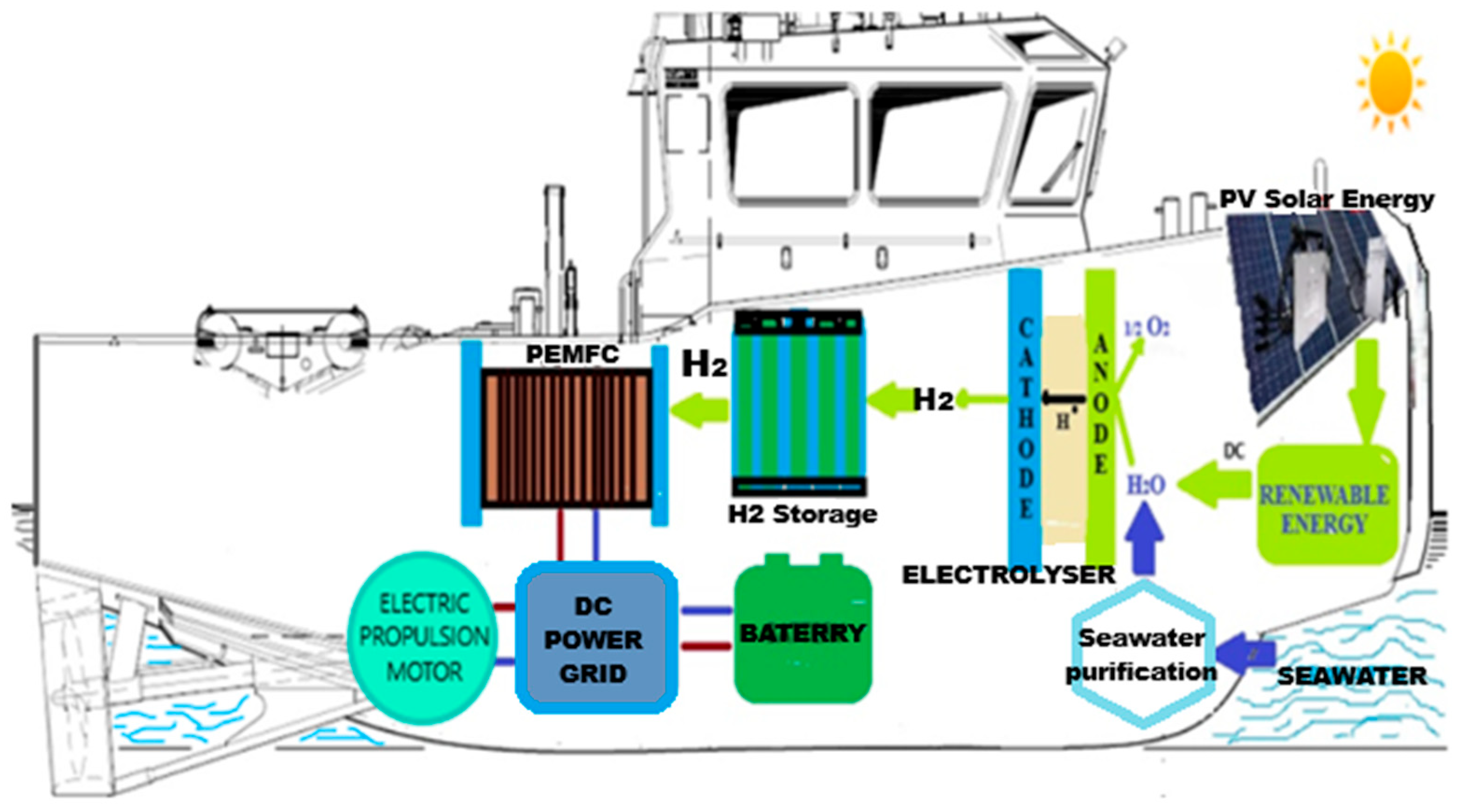
2.1.1. Hydrogen Produced via the Electrolysis of Water

Green hydrogen is produced through water electrolysis, and hydrogen production via this process is a viable option for fully utilising the surplus of renewable energy. Water electrolysis using renewable electricity is an auspicious approach among the various hydrogen production technologies. Water electrolysis based on renewable energy will enable the expansion of production by generating high-purity hydrogen (99.9%), which can also be used as a reactant in many industrial processes. Therefore, storing surplus solar and wind energy in hydrogen is quite promising. However, it should be borne in mind that renewable energy sources are intermittent and unstable, requiring a medium to store this energy. In the electrolysis process, water is the reactant dissociated into hydrogen and oxygen under the action of direct current, with the following reactions taking place:
At   the   anode :   H 2 O 1 2 O 2 + 2 H + + 2
At   the   cathode :   2 H + + 2 H 2
In   total :   H 2 O H 2 + 1 2 O 2
The water electrolysis can be achieved using four technologies: (a) Alkaline water electrolysis (AWE), (b) proton exchange membranes (PEM), (c) alkaline anion exchange membranes (AEM), and (d) solid oxide water electrolysis (SOE) [18]. A relevant community example based on a hybrid system consisting of solar energy networks and hydrogen storage systems is valuable. This study develops a solar-powered system integrated with a hydrogen storage system to meet the electricity, heating, and cooling demands of 1500 residential buildings in Southern Ontario, Canada. Hydrogen is integrated into the proposed system as an energy storage option. Hydrogen is stored in underwater balloons, which are called underwater hydrogen balloons. The heat recovery from the sewage is incorporated into the system to enhance the performance of the refrigeration cycles used in air conditioners and heat pumps, as it provides a cooler medium in the summer and a hotter medium in the winter. The electrical energy generated from solar energy through photovoltaic panels is utilised in water electrolysis to produce hydrogen. Its subsequent storage can power fuel cells to provide electricity to the community [19].
AEM (Anion Exchange Membrane) electrolysis is a type of water electrolysis technology used to produce hydrogen. Unlike proton exchange membrane (PEM) electrolysis, AEM electrolysis employs a semipermeable anion exchange membrane that conducts negatively charged ions (anions) to split water molecules into hydrogen and oxygen. One of the main advantages of AEM electrolysis is that it does not require high-cost noble metal catalysts. Instead, it can utilise low-cost transition metal catalysts. Like alkaline water electrolysis, the electrodes in AEM electrolysis operate in an alkaline environment. However, compared to PEM, the water requirements for AEM electrolysis are less strict, and a slightly alkaline solution can be used, reducing the risk of leakage and handling issues associated with highly alkaline solutions. Using this process, Enapter’s AEM electrolysers produce green hydrogen at a purity of 99.9% (up to 99.999% with a dryer) at a pressure of 35 bar, using only water and renewable electricity. Unlike PEM electrolysers, AEM electrolysers need no titanium corrosion protection or costly iridium. Our standardised production also leverages significant cost advantages. They likewise avoid the downsides of alkaline technology: most importantly, it is less able to cope with the load changes and dynamics of intermittent renewable energy [20].
Horizon has developed a new Anion Exchange Membrane (AEM) material combination that is expected to operate for over 60,000 h at an efficiency of up to 95%, creating a significant cost advantage compared to other electrolyser systems. Horizon’s new multi-layered, radical scavenging membrane achieves ion conductivity up to twice that of other products. It demonstrates superior mechanical strength and chemical stability, making it suitable for commercialising next-generation AEM electrolysers. Horizon’s innovation is at the heart of AEM electrolysers, combining proprietary anion exchange membranes and catalysts with novel electrode designs, yielding substantially increased ionic conductivity and electrocatalytic efficiency. To date, 95% efficient water electrolysis has been achieved in Horizon’s laboratories, demonstrating the feasibility of reducing the typical benchmark electrical consumption of electrolysers by 10–20% [21].
Designed to combine efficiency, safety, and versatility in a turnkey solution, Hygreen Energy’s new AEM electrolysers are customisable up to 100 Nm3/h (500 kW) of hydrogen generated and operate across a load range of 10% to 120%. The Company’s new AEM electrolyser system offers a range of unparalleled benefits: Plug-and-Play Solution designed for ease of installation and operation, the AEM electrolyser system comes as a fully integrated turnkey package, simplifying deployment and reducing time to market, Operational Safety and Stability, built with advanced safety features and highly rigorous standards, the system ensures reliable operation with minimised risk, Wide Operating Load Range, capable of adapting to varying loads, the system provides exceptional flexibility and efficiency across a broad spectrum of applications [22].
Hydrogen production on board ships is a viable solution, utilising water electrolysis powered by renewable energy sources (such as wind or photovoltaics) or excess energy from each system or waste heat. A study that evaluated potential solutions for hydrogen production that could be feasible to implement on board ships reveals that the polymer electrolyte membrane electrolyser is a promising opportunity to recover excess energy from each system or waste heat generated by the ship’s main engine. The exhaust heat of the exhaust boiler, the power turbine, and the auxiliary diesel generators are the primary sources of this excess waste energy. The study concludes that excess waste heat contributes to a reduction of approximately 0.5% of the fuel consumption for a ship, resulting in an annual savings of $42,740. This contribution varies depending on the ship’s operational profile. During anchorage and port parking, hydrogen fuel-based polymer electrolyte membranes (PEM) ensure clean and comfortable energy production while increasing energy efficiency and reducing carbon emissions. Although there are system inefficiencies and energy and exergy losses, the waste heat can be considered renewable due to its zero contribution to emissions [23].
Given the abundance of available water sources, a sustainable solution for ships is to produce hydrogen for on-board fuel cells using electrolysis units. A review of fuel cell and hydrogen technologies in marine applications shows in Figure 1 a combined fuel cell and electrolyser system based on renewable (photovoltaics) energy generation.
The system comprises a renewable energy unit, an electrolyser, proton exchange membrane fuel cells (PEMFCs), and other auxiliary units, including a seawater purifier and a hydrogen storage unit. Renewable energy captured from the sun through photovoltaic panels supplies the electrolyser with electricity to produce hydrogen, which is subsequently stored and used to power the fuel cells when operational. In this system, seawater must be purified before entering the electrolyser to prevent potential degradation of the quality of the hydrogen produced and its constituent elements. The ship’s power supply system can also extract energy from sources other than fuel cells, such as batteries or diesel generators [24].
Another study introduces a hybrid poly-generation system that utilises waste heat from fuel cells to generate electricity. The configuration comprises a solar photovoltaic system, fuel cells, and a thermoelectric device. This proposed system can provide electrical, thermal, and cooling requirements. A proton exchange membrane electrolyser (PEMWE) is used to provide the fuel and oxidant required for the fuel cells, with the electrical power needed for the electrolyser being supplied by the solar photovoltaic system. The heating and cooling demands are provided by the proton exchange membrane fuel cells (PEMFC) and a thermoelectric cooler (TEC), respectively. Figure 2 shows the schematic diagram of a hybrid system capable of generating power, hydrogen, heating, and cooling. In this system, the power produced by the photovoltaic panels is supplied to the electrolyser to produce hydrogen. The oxygen and hydrogen thus obtained feed the cathode and anode of the fuel cell, respectively, resulting in power and heat. The DC electrical power received from the PEMFC (WDC, PEM) is converted into AC electrical power (WAC, PEM) by the inverter. The heat from the fuel cell (QPEM) is also divided into two parts: one part (Q1) at temperature T is transferred to the TEG module to produce additional electrical power, and the other part (Q2) can be used for heating demands. Then, the electrical power produced by the TEG is transmitted to the TEC module, which absorbs the heat of the cooled space (QC) at temperature TC, thus providing the required cooling load. The water obtained from the PEMFC is also transferred to the water tank to feed the electrolyser [25].

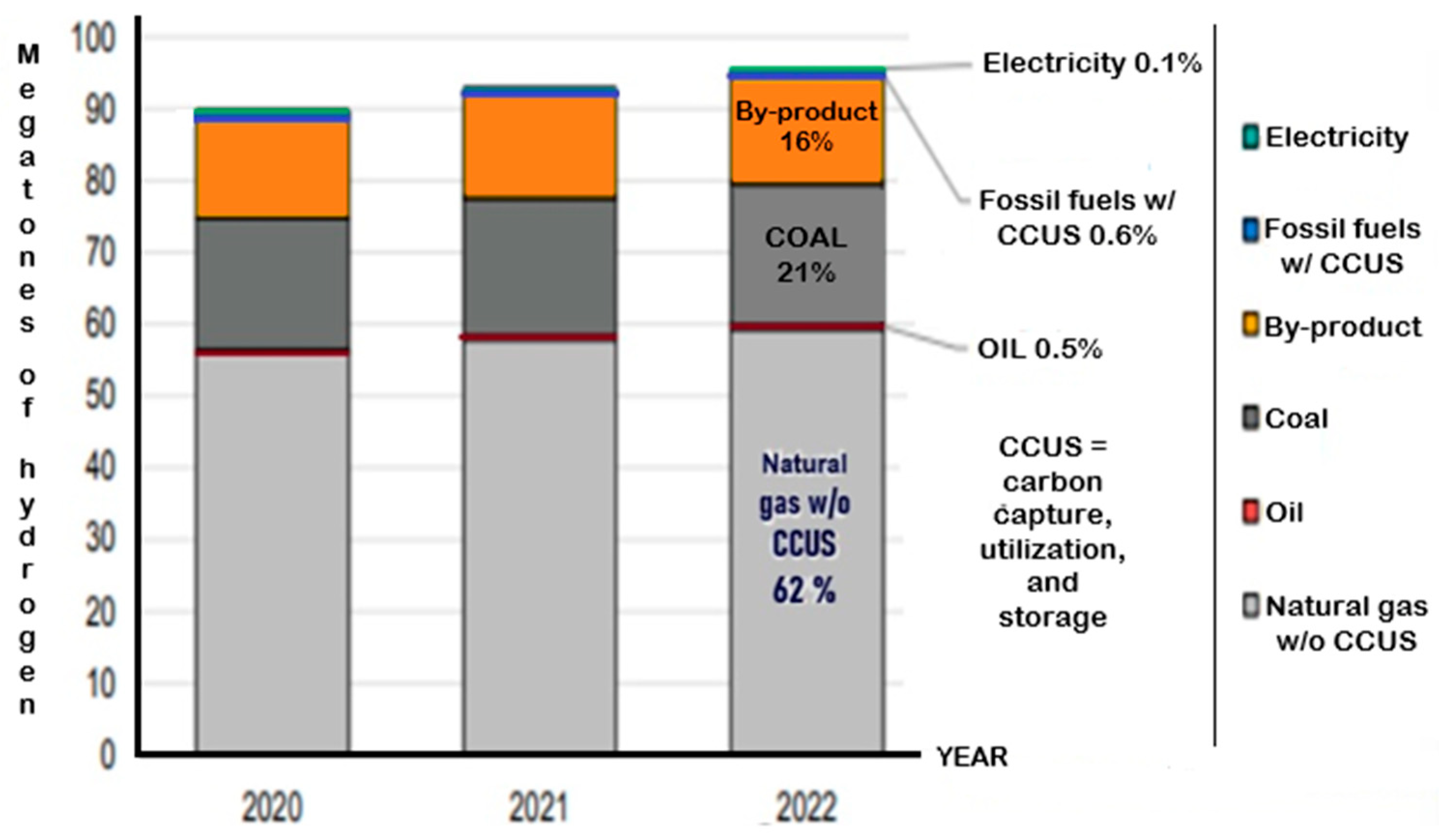
2.1.2. Hydrogen as an Industrial By-Product

Hydrogen can also be obtained as an industrial by-product. Global hydrogen production reached almost 95 Mt in 2022, an increase of about 3% compared to 2021 (Figure 3). In recent years, hydrogen as a by-product of industrial production in refineries and the petrochemical industry has consistently accounted for 16% of the hydrogen produced and is often used for other refining and conversion processes (desulfurisation, hydrocracking). Hydrogen was typically produced from fossil fuels, with carbon capture, utilisation, and storage (CCUS) from natural gas accounting for about 62% of its global production [26].
The hydrogen suitable for maritime applications is classified into various categories depending on its production methods and environmental impact. The carbon footprint of each type of hydrogen significantly influences its feasibility in decarbonising the maritime sector. Brown and black hydrogen, with a significant carbon footprint, is obtained through the uneco-friendly coal gasification method. Grey hydrogen, produced by steam methane reforming (SMR), accounts for over 95% of global production. The technology is affordable, but CO2 emissions are high. Blue hydrogen, obtained by combining natural gas reforming with carbon capture and storage (CCS), is a solution to reduce CO2 emissions. Factors such as natural gas transport distance and methane leaks influence the carbon footprint. Methane pyrolysis produces turquoise hydrogen, a low-carbon alternative with costs similar to grey hydrogen in areas with low natural gas prices. Water electrolysis using renewable energy sources remains the key solution for producing green hydrogen. Recent advances in water electrolysis technologies, including improvements in electrode materials and increased system efficiency, are driving the production of green hydrogen. However, this method’s weaknesses remain its economic viability and scalability. Integrating renewable energy sources into hydrogen production processes is essential to ensure sustainable and efficient maritime operations. Technological advances in seawater electrolysis allow the synthesis of hydrogen on board ships, stimulating the generation and storage of offshore hydrogen for maritime applications. These systems are beneficial offshore, where renewable energy can be harnessed from marine wind, wave or tidal sources. As subproducts of green hydrogen, yellow hydrogen, generated using solar energy, and pink hydrogen, used for electrolysis using nuclear energy, offer reliable alternatives with low carbon emissions without depending on weather conditions. Developing advanced nuclear reactors, such as small modular reactors, is anticipated to support the adoption of pink hydrogen. An innovative solution is aquatic hydrogen, produced from tar sands without CO2 emissions, with attractive production costs (0.23 USD/kgH2). Biohydrogen, produced through biological processes such as dark fermentation and photo fermentation, offers a sustainable alternative. If renewable raw materials and processes are applied, it can be classified as green hydrogen, making it a viable choice for maritime decarbonisation.
Table 4 provides a comparison of hydrogen production methods, highlighting their production processes, environmental impacts, which are crucial for assessing their applicability in maritime decarbonisation strategies [27].
Analysing the marine compatibility with hydrogen production methods, we find that hydrogen production for maritime applications must consider operational profiles, port infrastructure, renewable energy integration and decarbonisation objectives. The key conclusion highlights that PEM and Alkaline Electrolysis are the most operationally and environmentally suitable options for port-based hydrogen production linked to renewable energy systems, although constraints demand dependence on renewable electricity and high costs. Biohydrogen has average compatibility, but its low volumetric energy density is not recommended. Steam methane reforming, although a mature technology with low costs, is minimally compatible due to high emissions, while thermochemical and nuclear technologies are only theoretically feasible due to development and infrastructure gaps [6,7].

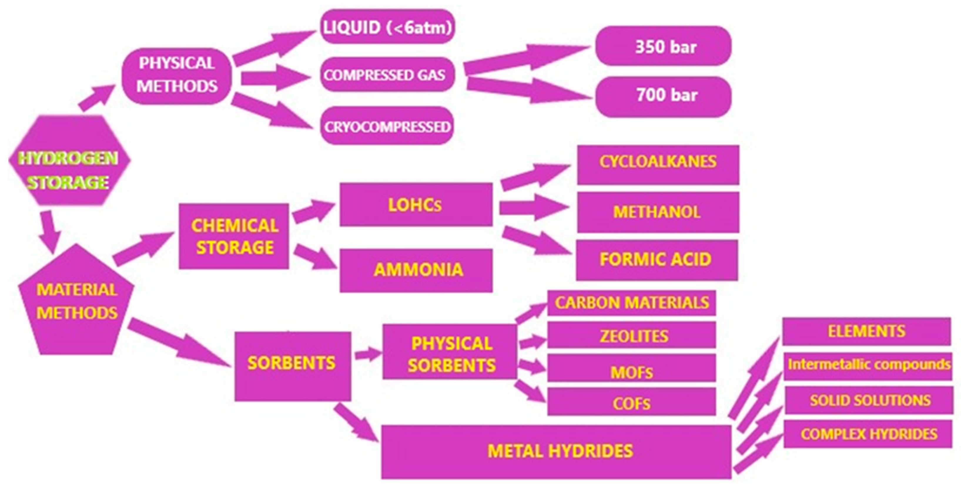
2.2. Hydrogen Storage in Marine Applications

The hydrogen storage system on board the ship is typically a complex system composed of several elements, including a tank or set of tanks (whose structure is determined by the storage method employed), valves, pipes, and, if necessary, a thermal management system. A real commercial hydrogen storage system on board the ship must have, as far as possible, large gravimetric and volumetric capacities, an operating range compatible with ambient conditions, fast charging and discharging kinetics, good cyclicity, a high and non-negligible safety level, and an affordable cost. In Figure 4, the most common and widely studied methods of hydrogen storage, including physical and chemical methods, have been illustrated: compressed gas, liquid, cryogenic compressed, chemical storage, and adsorbents [28].
Considering the storage density and cost ratio, hydrogen storage density will continue to increase as long as the compression pressure remains high, leading to increased costs. In the shipping industry, the amount of hydrogen required to be stored on board varies significantly depending on the type of ship, necessitating the identification of the most efficient ways to store hydrogen in marine applications. It is imperative to store as much hydrogen as possible in the case of large ships and marine equipment powered by hydrogen fuel cells while ensuring safety measures and controlling costs. Hydrogen storage on board ships remains the major challenge in clean maritime transport. The generally known storage methods include compressed hydrogen storage, liquid hydrogen, ammonia, FTS fuel, natural and synthetic gas, methanol, formic acid, organic aromatic liquids carrying hydrogen, and some solid-state hydrogen carriers, such as MgH2, NaAlH4, AB2-laves phase alloys, NaBH4, and NH3BH3. Compressed hydrogen requires the least amount of energy, while the most energy-intensive hydrogen storage is FTS diesel fuel, which requires almost three times as much energy. It is worth noting that, except for FTS fuels, LNG, and methanol, there is currently no bunkering infrastructure available for large ships, so this will likely be one of the significant challenges for the use of hydrogen in maritime transport, as will the development of suitable reactors for chemical hydrogen carriers (NaBH4, DBT, FA, ammonia). Liquid organic hydrogen carriers (LOHC) and solid hydrogen storage are less notable but promising, with liquid hydrogen and ammonia or methanol being essential research topics for marine hydrogen applications [29]. Hydrogen storage and accumulation technology using liquid organic hydrogen carriers (LOHC) is currently considered one of the most advanced solutions to the problems of hydrogen energy development. This thesis is supported by examples of pilot and industrial projects, particularly the SPERA Hydrogen project from Chiyoda Corporation. In that case, the technology is based on using hydrocarbon hydrogen carriers, such as methylcyclohexane/toluene or perhydrodibenzyltoluene/dibenzyltoluene pairs. These compounds were chosen due to their relatively wide availability and acceptable properties, including a relatively high hydrogen capacity (6.1 and 6.2% wt, respectively). There are several further examples of hydrocarbon LOHCs summarised in the reviews, including [biphenyl þ diphenylmethane], fluorene, diphenylmethane, 1,1,6,6-tetracyclohexylhexane and 1-(3cyclohexylpropyl)-3-ethylcyclohexane. Moreover, of interest for LOHC applications are also the nitrogen-containing heterocyclic compounds described in the literature, which are less suitable for widespread use as LOHCs due to non-optimal physical properties (for example, the high melting point of dehydrogenated decalin and bi-cyclohexyl) or limited availability (such as alkyl carbazoles) [30]. Chiyoda Corporation (Yokohoma, Japan) developed the SPERA Hydrogen system for large-scale hydrogen storage using the toluene/methylcyclohexane liquid organic hydrogen carrier (LOHC) couple. The catalyst is a partially sulfidized nanosized Pt cluster on Al2O3. The catalyst lifetime in methylcyclohexane dehydrogenation during laboratory trials was more than 10,000 h, the methylcyclohexane conversion was >95%, and the selectivity to toluene was >99%. The role of sulphur presumably consists of preventing the methylcyclohexane decomposition on the platinum cluster [31].

2.2.1. Hydrogen Storage Under Pressure

Hydrogen storage is still a major technological and scientific hurdle, with the most mature and developed of all technologies being gaseous storage technology (or compressed storage of a maximum amount of hydrogen in a given volume), presenting the best compromise in terms of mass density (the ratio of the mass of hydrogen stored to the total mass) and volumetric density (the volume of hydrogen stored to the total volume). The most important consideration when using compressed hydrogen is the material from which the hydrogen storage tanks are made, which must be able to withstand high pressures while also resisting the embrittlement caused by hydrogen. At the industrial level, progress has been made in terms of pressure, with tanks now using 350 bar, compared to 200 bar until a few years ago, and developments are moving towards tanks that can withstand pressures of 700 bar. High-pressure hydrogen storage systems must withstand extreme mechanical stresses, including impact and cyclic loading, over extended periods of operation. To achieve this, understanding their mechanical behaviour and associated damage mechanisms is essential to ensure structural integrity, safety, and storage efficiency [32]. High-pressure hydrogen storage becomes viable for an optimal volume, cost, and safety ratio. Initially, hydrogen storage tanks were made of aluminium. However, tanks are now manufactured from carbon fibre-reinforced plastic (CFRP) composite materials with high resistance and low mass but poor thermal conductivity [33]. Thomas Hafner et al. developed a test setup for the permeability of polymeric materials designed for hydrogen storage at high pressures, as polymers are essential materials for realising high-pressure hydrogen storage systems, especially type IV and V storage tanks. Extreme operating conditions, with pressures up to 875 bar and temperatures ranging from 40 °C to 85 °C, pose significant challenges for these polymeric materials; in particular, the hydrogen penetration through such materials—a key property for these applications—is strongly influenced by environmental conditions. Thus, tests performed at 400 bar and 800 bar with industrially manufactured high-density polyethene (HDPE) disc samples demonstrated effective characteristics of permeability, diffusion, and solubility coefficients in the developed test setup [34]. The pressurised hydrogen storage in PEMFC fuel systems is used sporadically and reserved for small-scale vessels operating for domestic and short-distance maritime transport or for demonstration operations on fuel cell ships. A major impediment is the need for 10–15 times more storage space for compressed hydrogen than for conventional fuel, according to [35].

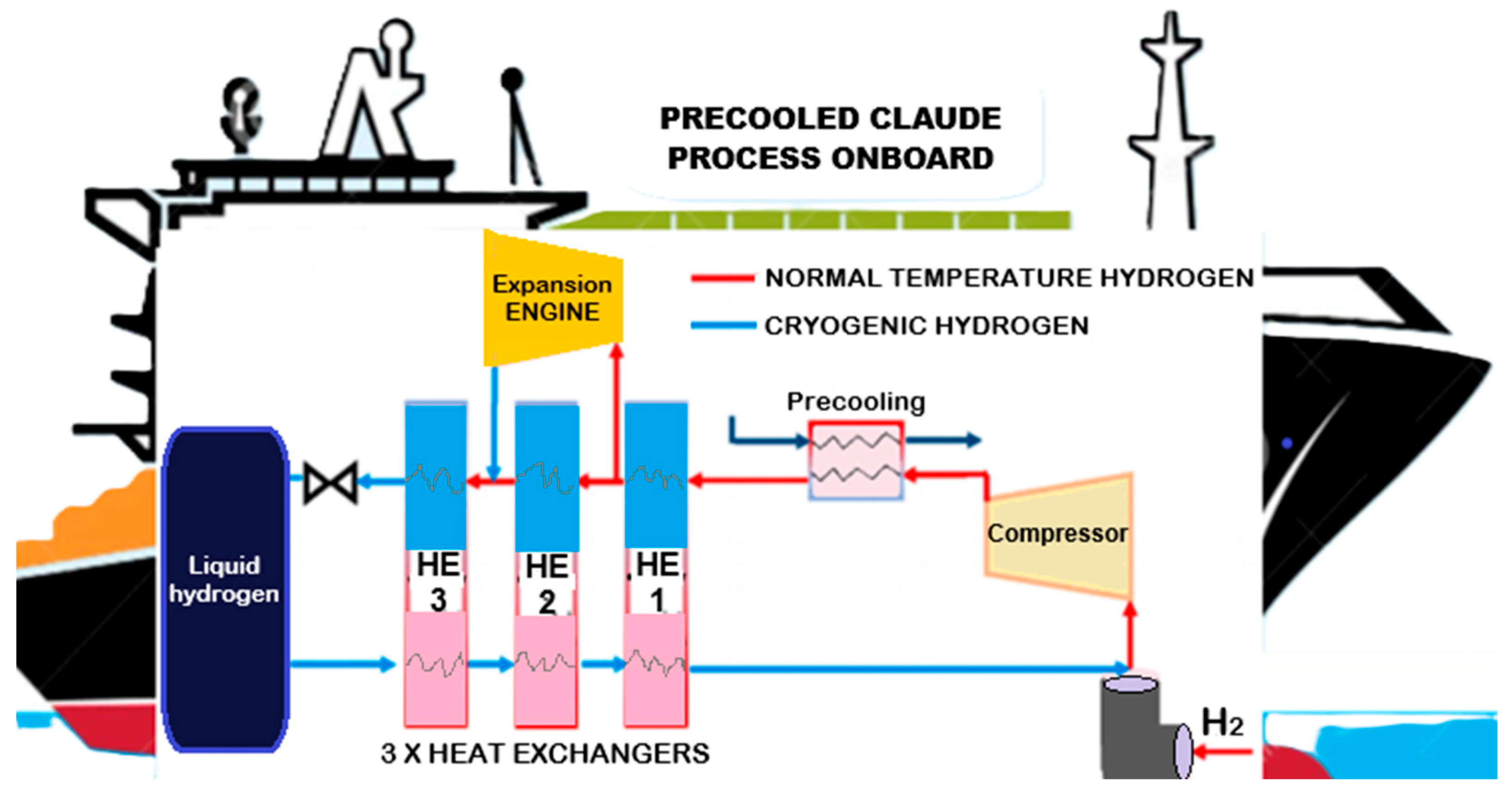
2.2.2. Liquid Hydrogen Storage

The widespread adoption of hydrogen requires a diverse range of hydrogen storage and transportation systems. Liquid hydrogen exhibits high potential for efficient storage and transport due to its high gravimetric and volumetric energy density and purity. Hydrogen liquefaction with high energy efficiency (low specific energy consumption) needs to be intensively developed to achieve a specific energy consumption of approximately 5–6 kWhel/kg-H2 shortly, thereby significantly reducing the total cost of liquid hydrogen production, storage, and transport. Storing hydrogen in liquid form is possible below 252.8 °C. Under these conditions, “the density of liquid hydrogen reaches up to 70.85 kg/m3, approximately 848 times higher than the density of hydrogen gas” [36]. There are several methods for liquefying hydrogen, including the Linde–Sankey process, the Claude process, the Collins process, and the Brayton helium cycle. According to research in the literature, in the 2010s, the Claude process for precooling hydrogen was preferred (Figure 5), a process that can be researched and developed on board ships using hydrogen energy. The Claude process involves a set of heat exchangers integrated into the system, one of which is used to precool the compressed hydrogen. This hydrogen passes through a heat exchanger, and part of the gas enters the expander, where it is expanded and cooled, contributing to the overall cooling process of the hydrogen. After three heat exchange processes, the hydrogen passes through an expansion valve and is stored as liquid hydrogen [24].
Liquid hydrogen storage is a critical issue, as above −253 °C, hydrogen vaporisation occurs, leading to pressure increases and losses in the liquid hydrogen tank. Hydrogen vaporisation can be mitigated by reducing the surface area-to-volume ratio of the tank, which can be achieved through the construction of double-walled ships and the use of a cryogenic cooler. A system combining liquid hydrogen storage with fuel cells has been proposed in a study, where the electricity generated from the recovered combustion heat is used to power the refrigerator, thereby cooling the passive insulation material and limiting heat loss. Compared to the traditional method that uses a refrigerator to recondense hydrogen directly, the proposed system enhances the refrigerator’s efficiency by utilising the cold shield cooled by the refrigerator (CRS) to increase the cooling temperature (from approximately 20 K to approximately 90 K). The heat from the difference between the hydrogen vaporisation temperature (20 K) and the hydrogen inlet temperature in the HFC (300 K) also improves the insulation efficiency [37].

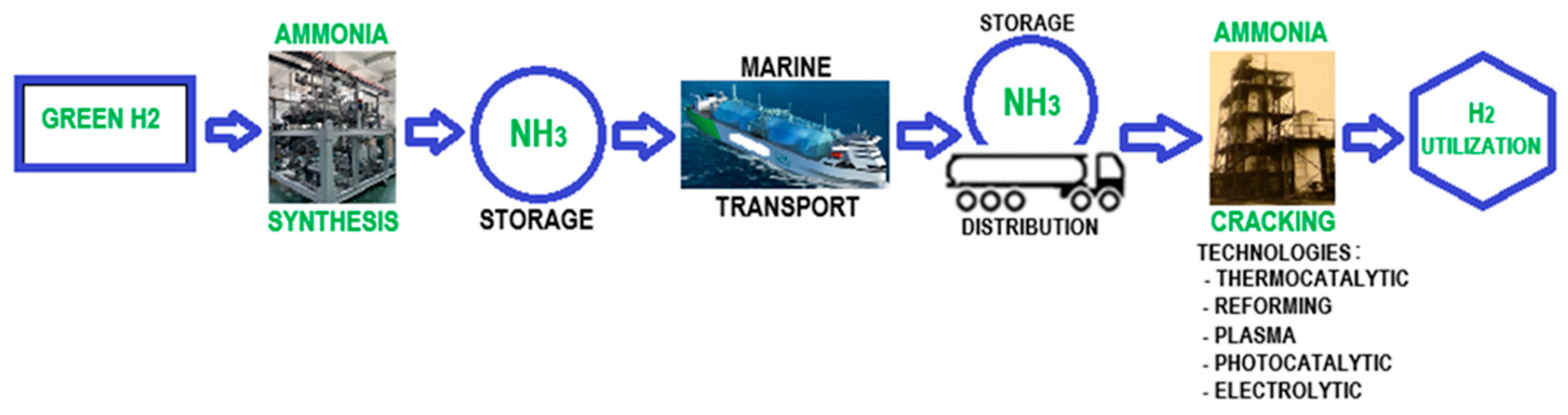
2.2.3. Hydrogen Storage Using Ammonia and Methanol

Compared to compressed hydrogen, liquid hydrogen carriers are the optimal means of hydrogen storage due to their high capacity for integration into existing chemical transport infrastructures. Challenges associated with their application include ensuring easy regeneration and high-density hydrogen storage. Currently, ammonia production is based on the Haber–Bosch process, which is described by the following reaction:
3 H 2 + N 2 2 N H 3 , Δ H = 91.8   k J / m o l
With a boiling point at atmospheric pressure of –33.5 °C, liquid ammonia storage is energy-efficient, with a hydrogen storage capacity reaching 123 kg H2/m3, compared to only 70.8 kg H2/m3 for liquid hydrogen [38]. Ammonia has attracted attention as an hydrogen carrier in the case of long-distance maritime transport; the value chain (Figure 6) includes NH3 synthesis from green hydrogen, the storage of liquid NH3 at the loading terminal, and the storage of NH3 at the unloading terminal, followed by distribution and cracking (via various technologies) to release H2 for further use [39].
Like ammonia, methanol is an interesting source of hydrogen because it has a relatively high hydrogen/carbon ratio, is liquid at ambient conditions, can be produced from biomass, and has a relatively low reforming temperature (200–300 °C) [40]. In addition, storage and transportation infrastructure for methanol already exists or can be easily adapted [41]. The catalytic reforming of methanol takes place based on an adiabatic process in a membrane catalytic reactor, defined by the following reactions:
C H 3 O H + H 2 O C O 2 + 3 H 2
C O + H 2 O C O 2 + H 2
C H 3 O H C O + 2 H 2
In the catalytic reactor, the operational parameters provide a temperature of 600 K, a pressure of 10 bar, and a steam-methanol ratio of 1.5, the Cu/ZnO/Al2O3 catalyst being optimal, due to its favourable catalytic activity, fast kinetics, as well as high selectivity and profitability, for methanol reforming reactions. A Pd-Ag membrane is also used to enhance methanol conversion efficiency and increase hydrogen purity in applications that require the highest possible hydrogen purity. The ultimate goal of using methanol and ammonia as green fuels or as hydrogen carriers is to produce electricity using fuel cell technology. The use of hydrogen carriers reveals better technical and economic performance and an exceptionally high efficiency compared to the direct use of methanol or ammonia (35–40%, compared to the direct alternatives of 15–25%). This better efficiency is reflected in a lower operating cost (approximately 600–800 e/MWh). If we consider the storage and transportation costs in both cases, using methanol or ammonia is a promising alternative with an essential role [42].

2.2.4. Solid Hydrogen Storage

Metal hydrides are formed through the metal lattice’s reversible dissociative chemisorption of hydrogen gas. The reaction of the hydrogenation–dehydrogenation mechanism is as follows:
M + x 2 H 2 M H x
M is a metal, and x is the amount of hydrogen attached to the metal. Metal hydrides are a highly effective method for storing large volumes of hydrogen safely and compactly. The metals whose hydrides have proven to be the most effective for hydrogen storage are Mg, Ni, Ti, Pd, and Sc. The life cycle of metal hydrides can be extended if the metals they contain are derived from rare earths. Recent studies have shown that materials based on carbon substitution at ambient temperatures exhibit improved chemical kinetics and enhanced hydrogen absorption and desorption. Since graphite reduces the internal resistance and increases the hydrogen storage capacity over time, materials substituted with graphene have storage capacities up to 899.4 mAh g−1. Still, for example, Mg0.8Ti0.2 also offers a reasonably high discharge capacity (535 mAh g−1), with the maximum being found under conditions using porous bituminous carbon (3485 mAh g−1). The storage capacity values of various hydrogen storage materials are presented in Table 5 [43].
In summary, Table 6 presents a comparative analysis of hydrogen storage technologies, which allows alternatives, from compressed gas and cryogenic liquid storage solutions for transportation, to solid-state, adsorption-based and ammonia-based systems, designed to meet compact and long-term storage requirements. Volumetric and gravimetric capacities, pressure and temperature prerequisites, energy density, safety characteristics, economic implications and applicability in various contexts are analysed [44].
When it comes to the storage of alternative fuels in generic fuel cell hybrid marine power plants (FCMHPPs), a breakdown of the literature shows that hydrogen, natural gas, ammonia and methanol are the four fuels in focus. The main types of ships highlighted in the reviewed literature include cruise ships (defined as ships with long sea voyages across the oceans), passenger ships (which include coastal ferries, tourist boats, ro-pax ferries, domestic ferries), container ships, cargo ships and tankers (oil tankers, chemical tankers), as well as other special purpose ships. The results of the analysis indicate that pure hydrogen is used as fuel in 56.6% of cases, LH2 in 22.2%, CH2 in 17.2%, metal hydrides in 4.1% and hydrogen in 13.1%. In addition, LNG is stored in 28.3% of cases, ammonia in 10.1% and methanol in 5%. Given the importance of ammonia and methanol as fuels in marine fuel cell hybrid power plants (FCMHPPs), they are less studied in depth than hydrogen and LNG, which highlights a possible knowledge gap [45].
Hydrogen energy storage systems (HES) represent an innovative approach to decarbonising marine operations, effectively addressing environmental and operational dilemmas. Technological advances in reducing the costs associated with electrolysis and the emergence of innovative storage solutions have significantly improved the viability of hydrogen for maritime applications. Technological advances in reducing the costs associated with electrolysis and the emergence of innovative storage solutions have significantly improved the viability of hydrogen for maritime applications. Empirical implementations, such as the hydrogen-powered ferries operating in Norway or Japan’s initiatives to develop hydrogen port infrastructure, illustrate the transformative potential of hydrogen in the maritime sector. These systems have successfully reduced greenhouse gas emissions, nitrogen oxides and particulate matter. However, despite these advances, safety concerns regarding hydrogen storage, the lack of supporting infrastructure and high production costs remain [44].

2.3. Hydrogen Transportation in Marine Applications

The efficiency, costs, and GHG emissions of hydrogen transport to an industrial user were studied by Satu Lipiäinen et al., who compared hydrogen transport using natural gas pipelines, synthetic methane transport through existing pipelines, hydrogen transport through new hydrogen pipelines, maritime transport of liquefied hydrogen, and on-site electrolysis. For moderate transport distances (500 km), the results confirm that on-site electrolysis and pipeline transport (both natural gas and new hydrogen) are the most feasible options, with maritime transport of liquefied hydrogen and synthetic methane transport through existing pipelines being less efficient due to significant conversion losses and the need for additional investments in processes. Even though the costs of transportation and infrastructure investments are high, the dominant component of the costs is given by hydrogen production; however, precise estimation of costs, efficiency, or GHG emissions is difficult at this stage of development [46]. In addition to the classic and established types of hydrogen transport, a novel solution studied by Julian David Hunt et al. involves transporting hydrogen in balloons as a gas at atmospheric pressure, utilising natural wind flow to carry the balloon to its destination. The factors on which this type of transport depends are the average wind speed, atmospheric pressure, and temperature. The ideal altitudes for hydrogen transport by balloons are between 1 and 8 km (6.2 km the most suitable). The hydrogen pressures in the balloon vary from 0.25 to 1 bar. The estimated cost for the transport of a hydrogen balloon with a volume of 1 km3 is 260 million USD, which represents a hydrogen transport cost of 0.08 USD/kg, which is approximately 12 times cheaper than the cost of transport as liquefied hydrogen, between the USA and Europe [47].

2.3.1. Transport of Hydrogen Gas

Among the most common methods of transporting gaseous hydrogen (compressed at pressures of 350–700 bar) is in specialised cylinders or tubular tanks, a viable method only for smaller volumes over short and medium distances. For long-distance transportation, the safest and most practical method for transporting significant quantities of hydrogen is through pipelines in compressed form. Reaching a maximum level of technological maturity, where the technology is in its final form and operates under the full range of operating conditions while also making production methods cost-effective, requires a share of hydrogen on the energy market of at least 10%. An opportunity and a challenge is the transition from methane (CH4) to hydrogen as an energy carrier within the existing pipeline transport infrastructure in the form of a hydrogen-rich mixture. Facilitating the transition to hydrogen through this method requires strategies regarding safety and efficiency, which involve, on the one hand, the incremental integration of hydrogen, i.e., mixing it with methane in concentrations ranging between 5 and 30%, and, on the other hand, the adaptation and conversion of large-scale methane combustion systems for the use of hydrogen, capitalising on existing infrastructure and technologies in this regard [48]. The benefits of transporting hydrogen in a gaseous state are a simple equipment structure, relatively low costs, and high hydrogen loading/unloading speed. At the same time, the disadvantages include the low mass density, low hydrogen storage efficiency, and ensuring safety conditions, given that hydrogen tends to induce the embrittlement of metals [49].

2.3.2. Liquid Hydrogen Transportation

One of the challenges of liquid hydrogen transport is hydrogen evaporation, a process that can be turned into a utility. According to a study, a liquefied hydrogen transport ship (LH2) with a capacity of 50,000 m3 and a hydrogen evaporation rate (BOR) of 0.4% per day, with a hybrid power system composed of a fuel cell (FC) and a lithium-ion battery (LIB), can increase economic efficiency, minimising the cost over the life cycle of the ship with the help of optimisation tools to determine the financial distribution of power between FC and LIB. Thus, the evaporated hydrogen (BOH) fuels the FC on the move (approximately 45.2%). When the ship is in port, the surplus evaporated hydrogen (BOH) is used to generate electricity, which can be transferred to the shore grid. At the same time, the LIB (Lithium-Ion Battery) can effectively manage load fluctuations and mitigate the deterioration of the FC performance. The results reveal that the maritime transport of LH2 will play an essential role globally in the decarbonisation chain [50].
In line with various carbon neutrality policies worldwide, the market for carbon-neutral technologies, such as renewable energy, hydrogen, CCUS (Carbon Capture, Utilisation, and Storage), and carbon removal technologies, continues to expand domestically and internationally. Kawasaki Heavy Industries’ shipbuilding division has a proven track record in building liquefied gas carriers of various sizes (1 × 1250 m3 ship, 4 × 10,000 m3 ships, and 4 × 40,000 m3 ships). Since the construction of the world’s first liquefied hydrogen carrier, SUISO FRONTIER, KHI has contributed to commercialising large liquefied hydrogen carriers by completing their basic design. In 2022, KHI demonstrated maritime transportation and cargo handling between Japan and Australia using SUISO FRONTIER, the world’s first liquefied hydrogen carrier we built, demonstrating the feasibility of an international liquefied hydrogen supply chain. In the medium to long term, liquefied hydrogen is expected to be the most cost-effective and promising energy carrier [51]. Maritime liquid hydrogen transport (LH2) is carried out efficiently using specialised tankers with transport capacities exceeding 10,000 m3, typically for intercontinental routes.
On the other hand, land transport of LH2 has many options of methods and sizes of tanks/tanks, usually the size of these tanks being 30–60 m3, which means approximately 2100–4200 kg, while, for rail transport, specialised tank wagons with a capacity of up to 115 m3 (approximately 8000 kg) are used. Given the safety conditions imposed by thermal expansion, the filling is limited to approximately 85% of the tank’s total volume. The transfer of liquid hydrogen from transport tanks to storage tanks has an efficiency of 0.3–0.6% per day, while additional hydrogen evaporates. Therefore, storing liquid hydrogen at a lower pressure means a smaller volume of hydrogen is stored, and vaporisation occurs during the transfer of liquid hydrogen from the transport tank to the storage tank due to the temperature difference between the liquid hydrogen, the pipelines, and the storage tank. To minimise losses, liquid hydrogen transfer must be carried out in an isolated system [36]. Recent research has focused on identifying technical solutions for the development of alternative propulsion systems based on hydrogen, as well as a hydrogen distribution infrastructure suitable for maritime transport. A recent study analysed an offshore wind farm’s energy and economic performance integrated with a liquid hydrogen production system to refuel ships at sea. The study developed optimisation techniques dedicated to identifying optimal technical solutions in terms of component sizes and management strategies that ensure the minimum levelized cost of hydrogen (LCOH). Results revealed that an innovative configuration proposed for a liquid hydrogen production plant is capable of producing 317 tons of green hydrogen per year, with a levelized cost of hydrogen (LCOH) of €16.77/kg, by supplying 19 MW of electricity produced by an offshore wind farm to a 5 MW proton exchange membrane (PEM) electrolyser. At this stage of research, the calculated LCOH can be considered quite high; its reduction can be achieved by increasing the production capacity of liquid hydrogen, generating income from the sale of surplus electricity, as well as lowering the costs of offshore platforms (reuse of obsolete infrastructures), resulting in an LCOH decrease of approximately 10 €/kg [52]. A solution under development for hydrogen storage and transport is liquid organic hydrogen carriers (LOHCs). The hydrogen storage technique in LOHCs is based on the hydrogenation of liquid and semi-liquid organic compounds in LOHCs.
Then, the hydrogenated molecules are stored and transported, and finally, through dehydrogenation, hydrogen is released to power the systems. Hydrogenation and dehydrogenation are carried out catalytically for several cycles. Thus, LOHCs are a defining, cheap, and simple hydrogen storage and transport solution, as the molecules can be easily dehydrogenated and used as energy sources. LOHC molecules have been analysed based on stability, storage capacity, catalysts used, and reuse. The stability of LOHCs can be improved by decreasing the dehydrogenation enthalpy of these molecules. Using catalysts decreases the activation energy of the dehydrogenation of LOHC molecules, thereby requiring a lower dehydrogenation temperature. Future research should focus on developing efficient catalysts for dehydrogenating LOHC molecules at low temperatures, making the system economically viable. The similarity of LOHCs to crude oil suggests the potential for utilising existing systems for energy production, with dibenzyl toluene and toluene being LOHC candidates with significant prospects for large-scale production [53].
Within the port infrastructure level analysis, a case study presents the ability of hydrogen to complement broader energy transition efforts and its ability to align port operations with long-term sustainability and fuel diversification goals. The pathways to reduce emissions in port operations due to the potential alternative of hydrogen technology are the result of the analysis within the case study on the Port Authority of New York and New Jersey (PANYNJ). The analysis also highlights the potential of hydrogen to negate the CO2 emissions of CHE, HDV and OGV, while addressing operational and regulatory challenges. Adopting hydrogen in port operations offers co-benefits that extend beyond emissions reduction. These include improvements in air quality, improved public health outcomes, and increased energy resilience. Achieving these outcomes requires an integrated approach that includes life cycle assessments, renewable energy-based hydrogen production, and the development of localised supply chains [54].
The Clean Hydrogen Partnership is a unique public–private partnership supporting European research and innovation (R&I) in hydrogen technologies. During 2023, this organisation conducted studies and research on hydrogen in ports and coastal industrial areas, providing comprehensive analyses, summarised in three reports, on the following main topics:
o
Report no. 1 (March 2023), which addresses the demand and potential of the hydrogen market, hydrogen supply, storage and distribution and hydrogen business models in ports,
o
Report no. 2 (September 2023), which in addition to gap analyses and recommendations on priority areas for research and innovation projects, safety-related regulations, codes and standards and non-technical provisions (policy, regulatory, strategic, governance, investment, etc.) addresses the governance of hydrogen-related activities and infrastructure and hydrogen carriers in port areas, hydrogen and hydrogen carriers in ports, in the vicinity of ports and in the broader context of the port area,
o
Report no. 3 (December 2023) presenting case studies on hydrogen production, port equipment for hydrogen consumption, maritime transport for hydrogen consumption and hydrogen import.
When comparing fuel options for international shipping, methanol and ammonia are the most promising, and the main conclusions of the Clean Hydrogen Partnership’s analysis on this topic state:
Green hydrogen fuels, in the medium and long term, will be the foundation for the decarbonization of the international maritime sector.
Ethanol and ammonia are the most promising (ammonia is more attractive due to its zero carbon content).
Hydrogen could be an option for short distances, but for longer distances, its role is quite limited due to the ample space required.
The production costs of renewable fuels are currently high, but will become competitive in the coming decades.
The choice of fuel depends largely on fuel price and availability, supply chain, costs of adapting ship and port infrastructure, technological maturity, sustainability issues, net environmental performance and economic viability. The adoption of climate-neutral sources could come sooner with government intervention.
The energy density of different fuels and the implications for onboard storage are elements that require further analysis (ample storage space means less cargo capacity and lower revenues).
For domestic shipping, batteries could also be an option [55].

3. Fuel Cell Technologies for Marine Applications

Currently, fuel cell efficiencies range from 40 to 60% in actual operation, which exceeds the efficiency of conventional internal combustion engines. Fuel cells have advantages in marine applications, such as environmental benefits, energy security, quiet operation, improved reliability, support for sustainable development, and safety.
The advantages of using Hydrogen Fuel Cells in Marine Applications are: environmental benefits, energy security, efficiency, improved safety, reduced weight and space requirements, improved reliability, regulatory incentives, supporting sustainable development, and safety concerns. On the other side, the disadvantages of using the Hydrogen Fuel Cells in Marine Applications are: lack of infrastructure, cost, safety, technical challenges, limited availability of suitable fuel cell systems, environmental impact, regulatory and policy challenges, public perception and acceptance, and infrastructure development [56].

3.1. Fuel Cells for Marine Applications

An overview of recent research shows that fuel cells have potential for use in hydrogen-based maritime transport. The most promising options are proton exchange membrane fuel cells (PEMFCs), molten carbonate fuel cells (MCFCs), and solid oxide fuel cells (SOFCs) [35].
Proton exchange membrane fuel cells (PEMFCs) result from meticulous research and understanding of the complex electrochemical and physical phenomena. These include polarisation curves, reactant and product species profiles, species velocities, and temperature distribution, all described by coupling reaction kinetics with mass, momentum, energy, and charge transport processes. This depth of understanding reassures us of the reliability of this technology in our quest to decarbonise the transportation sector [57]. As an advantage, PEMFCs have a fast start-up time, making them suitable for meeting the mobility requirements of various equipment. PEMFCs also have a high energy density, which allows them to occupy a small installation space (excluding auxiliary equipment) while meeting power requirements. The efficiency of high-temperature PEMFC technology was demonstrated with three 30 kW stacks in a project carried out on board the MS Mariella and another Norwegian project, which integrated a 12 kW HT-PEM system in a small-class ferry [58].
The molten carbonate fuel cell (MCFC) is a high-temperature fuel cell capable of operating at 700 °C, using hydrocarbons like methane and natural gas as fuel sources [59]. The EMSA study mentions that the Viking Lady, a fuel cell ship, is equipped with a 320 kW MCFC system powered by LNG and an “internal reformer unit.” The electrical efficiency of the FC system is 52%, corresponding to a net power of 44.1–100% load [58].
Solid oxide fuel cells (SOFCs) can operate at higher temperatures than MCFCs, up to 1000 °C. The solid electrolyte in this type of fuel cell has better structural stability than the electrolyte in MCFCs. Based on their characteristics, SOFCs are considered to have great application potential for medium—and long-range ships, especially for electricity generation in hybrid energy systems with heat recovery units [60].
Despite some positive results and subsequent research, “PEMFC, MCFC, and SOFC fuel cells” are usually used as auxiliary resources for ship power supply systems in marine applications.
Regarding fuel cell technologies marketed as solutions for marine applications, we exemplify the Rubri company, which provides R&D services and customised solutions for hydrogen fuel cell ships. The power system of the island wave energy ship consists of a fuel cell system, a power system, a propulsion system, an energy management system, an inerting system, and a marine load. It features a modular design for both the drive and power platforms. The power of a single power module is 200 kW, which can be quickly expanded to cover mass production scenarios, such as speedboats up to 12 m in length, yachts between 12 and 30 m, cruise ships with less than 500 passengers, ferries, and official ships for lakes and inland rivers, among others. Remarkably, the vessel can achieve a strong and efficient linear torque output while producing zero carbon emissions and low consumption, making it environmentally friendly. It also reduces noise by over 90% and maintenance costs by over 50% [61].
The MV Sea Change is the world’s first zero-emission, 100% hydrogen fuel cell-powered commercial ferry. The project to develop the Sea Change was unique in that it captured and documented lessons learned throughout as a requirement of its government funding. These project learnings include the vessel design, construction, testing, fuelling, and entry into the public ferry fleet in San Francisco. The performance date indicates an overall fuel cell efficiency of 45.7%. An emissions analysis showed a 90% reduction in GHG emissions (using renewable hydrogen) compared to a fossil-fuelled diesel equivalent. Regardless of how hydrogen is produced, the MV Sea Change dramatically reduces lifecycle criteria pollutant emissions [62].
In an approach to the use of fuel cells in marine applications, for achieving an energy-efficient design of ships, the following types of fuel cells are to be considered and analysed as potential energy sources:
i. Low-temperature proton exchange membrane fuel cells (LT-PEMFC)
ii. Direct methanol fuel cells (DMFC).
iii. Alkaline fuel cells (AFC).
iv. Molten carbonate fuel cells (MCFC).
v. Phosphoric acid fuel cells (PAFC).
vi. Solid oxide fuel cells (SOFC).
vii. Liquefied natural gas fuel cells (LNGFC).
viii. High-temperature proton exchange membrane fuel cells (HT-PEMFC).
ix. Biomass fuel cells (BFC).
Table 7 presents the potential naval applications of various types of fuel cells and their key parameters, demonstrating their viability in maritime contexts [63].
Fuel cells have developed significantly and are widely used in land-based vehicles or energy systems, but their integration into the maritime industry is still in its early stages. The distinctive requirements and challenges that ships present for fuel cell systems, compared to land-based vehicles. Thus, the operational environment of ships is characterised by high corrosion due to salt water, unpredictable weather conditions, requiring continuous operation for long periods, that is, energy sources that offer high energy density and exceptional durability. Another specific characteristic is the size of ships, which requires robust and highly efficient power supply systems. Ship emissions are high, implying a more pronounced environmental impact, which requires adopting cleaner energy sources. Not least, economic considerations are distinct in the case of ships, with a longer lifespan benefiting from operational models that influence initial investments and operational costs over the entire lifespan, highlighting the uniqueness of maritime transport [63].
Hydrogen fuel cells convert chemical energy directly into electrical energy through electrochemical reactions. Their selection for marine applications depends on the type of ship, the operating cycle and space constraints. Research results confirm that compact PEMFC systems, with fast response to load tracking, are the most suitable for propulsion and auxiliary power on ferries and offshore vessels, even though they are sensitive to impurities and have high costs. Due to high operating temperatures and slow start-up, SOFC systems are moderately suitable for marine use, offering prospects for larger ships requiring cogeneration. PAFC/AFC/MCFC are less suitable for marine use due to their large volume, high costs and difficulty in thermal management [64].
In analysing the most suitable fuel cells for marine applications (PEMFC), it is very useful to address their degradation under the action of the marine environment, because ships usually operate in isolated areas and require reliable and durable energy and propulsion systems.
Degradation mechanisms such as: radical degradation of PFSA (Perfluorosulfonic acid membrane component), carbon corrosion, catalyst inactivation, or reactant blocking, are used to link the causes of degradation (contamination, load-based stress and motion) to various deterioration indicators (impedance measurements, exhaust gas analysis and imaging techniques).
Degradation studies based on contamination, load, vibration and tilt provide a factual basis for analysing PEMFC degradation in marine applications.
In analysing marine PEMFC degradation, A. Broer et al. They also identified various areas for further research, including degradation due to the interconnected effects of marine driving cycles, marine air salinity, hydrogen carriers and their residues, long-term marine vibrations, and dynamic tilting [65].

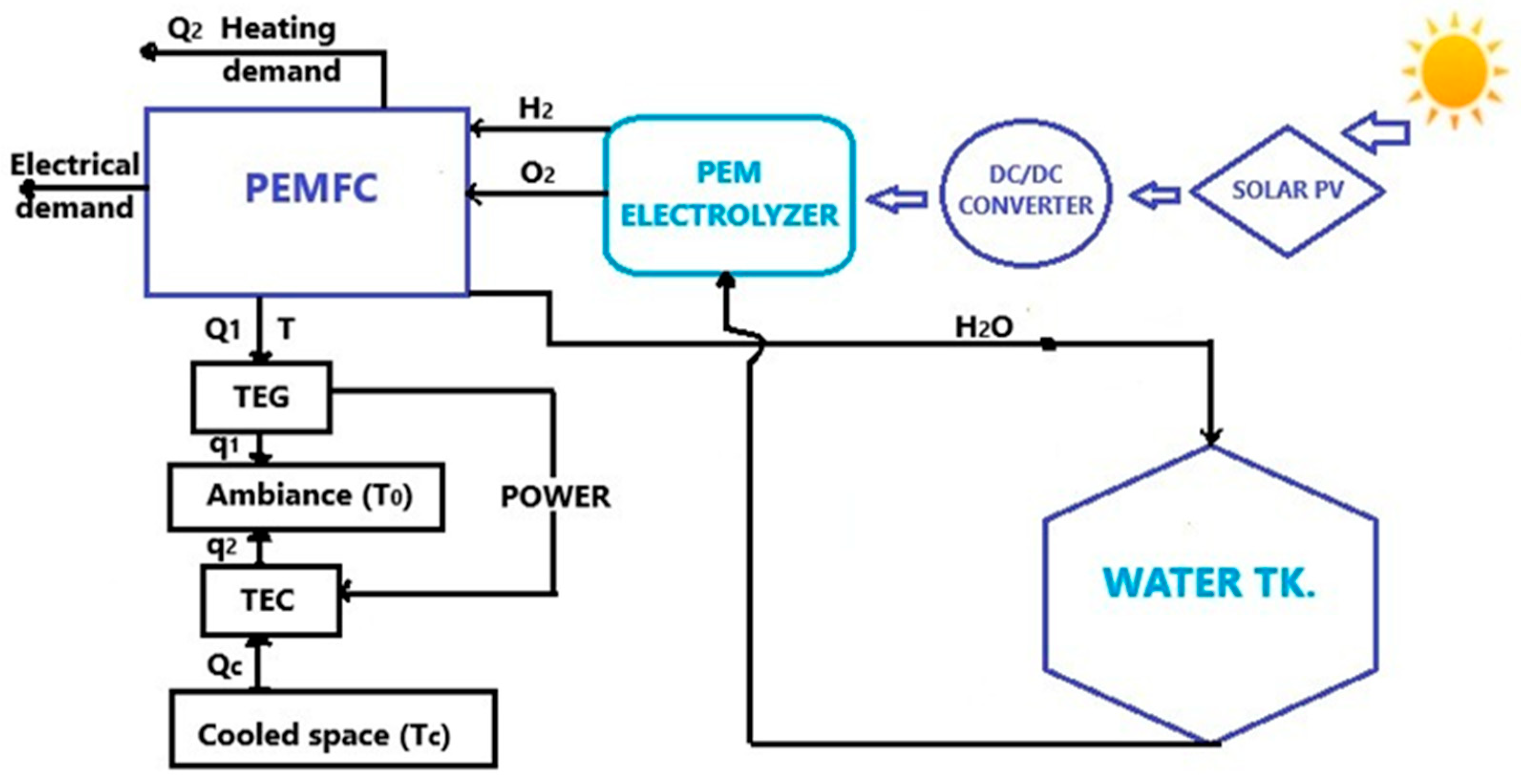
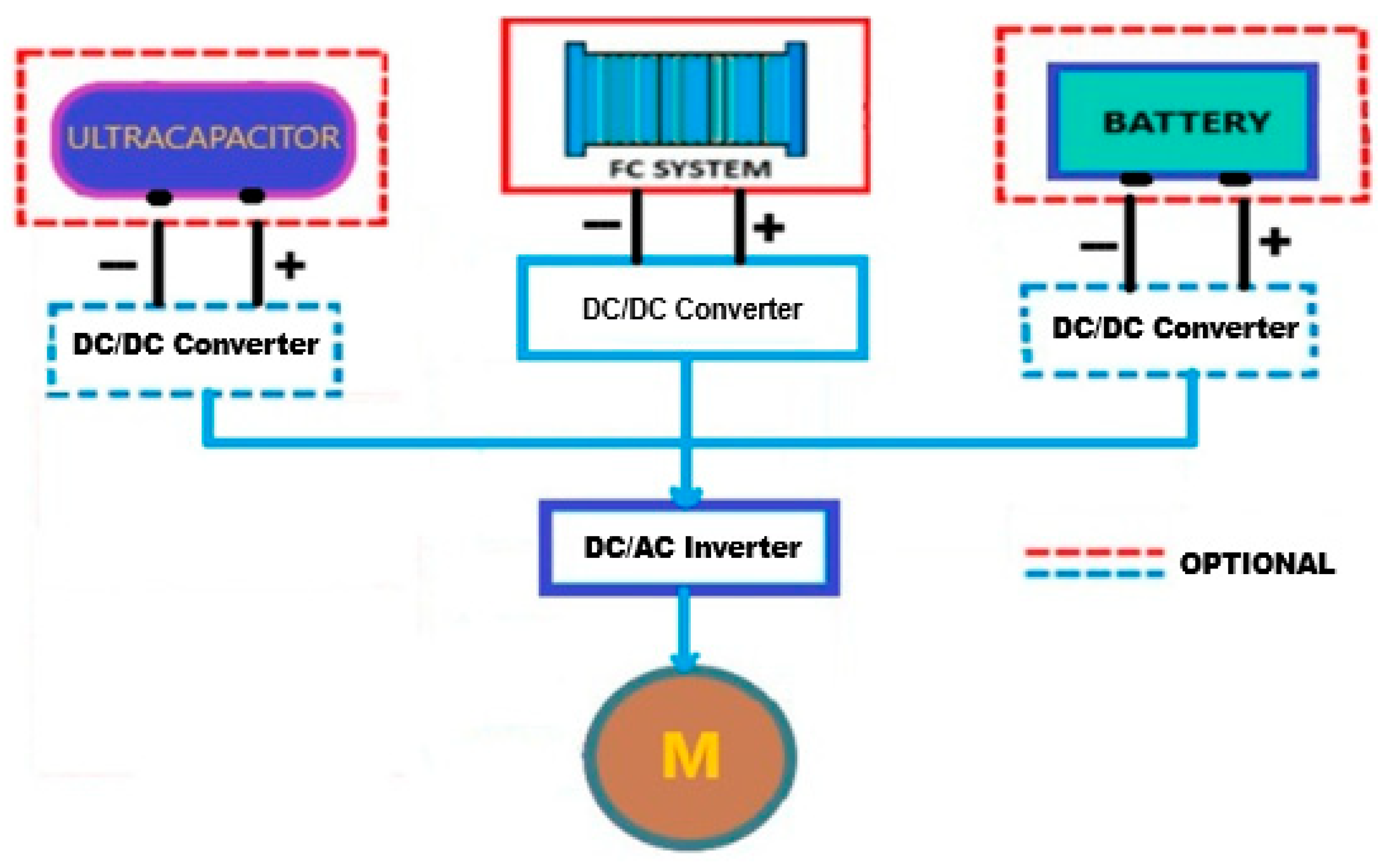
3.2. Hybrid Fuel Cell Power Systems. Energy Storage

Figure 7 provides a block diagram of a modular hybrid fuel cell–energy storage power supply system. It contains a fuel cell subsystem, energy storage equipment, a DC/DC converter, an inverter, and an electric motor. Low-temperature fuel cells and high-temperature fuel cells can serve as the primary power source for small ships or as auxiliary power for larger ship types. The storage equipment can be a battery or a supercapacitor, aiming to balance load variations and cover peak power. Obtaining alternating current is achieved using a DC/AC inverter, which converts the current from the DC/DC converters of the fuel cells and the energy storage equipment. Increasingly, the composition of such hybrid systems has been applied to more maritime ships, contributing to reduced fuel consumption and extended fuel cell life [66]. A hybrid diesel generator (DG)–high-temperature fuel cell (HT-PEMFC)–battery (BAT) system was implemented within the RiverCell river vessel. Projects such as RiverCell by the German consortium “e4ships” include feasibility studies and the future role of fuel cells (main or auxiliary power supply) [67].

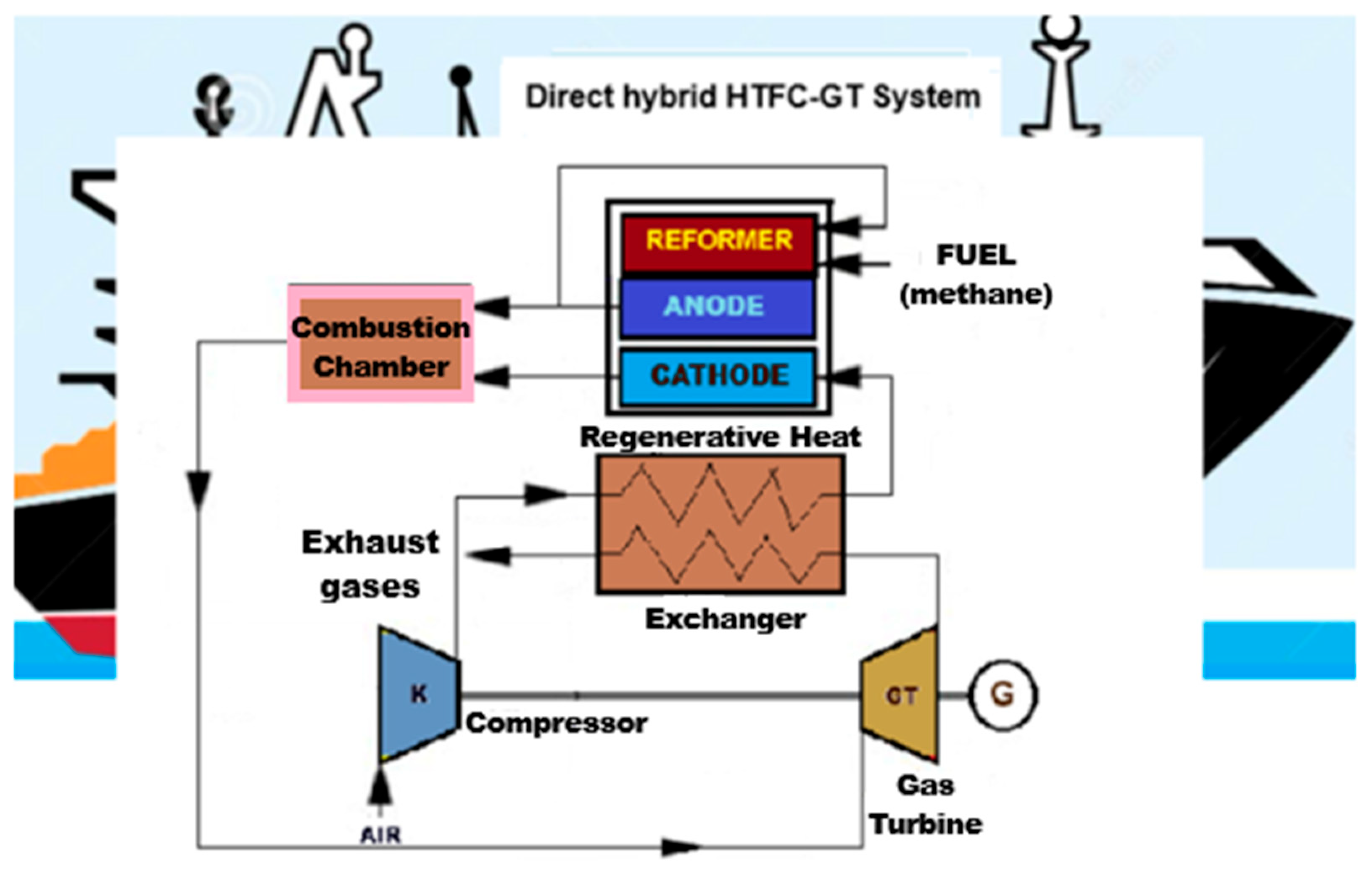
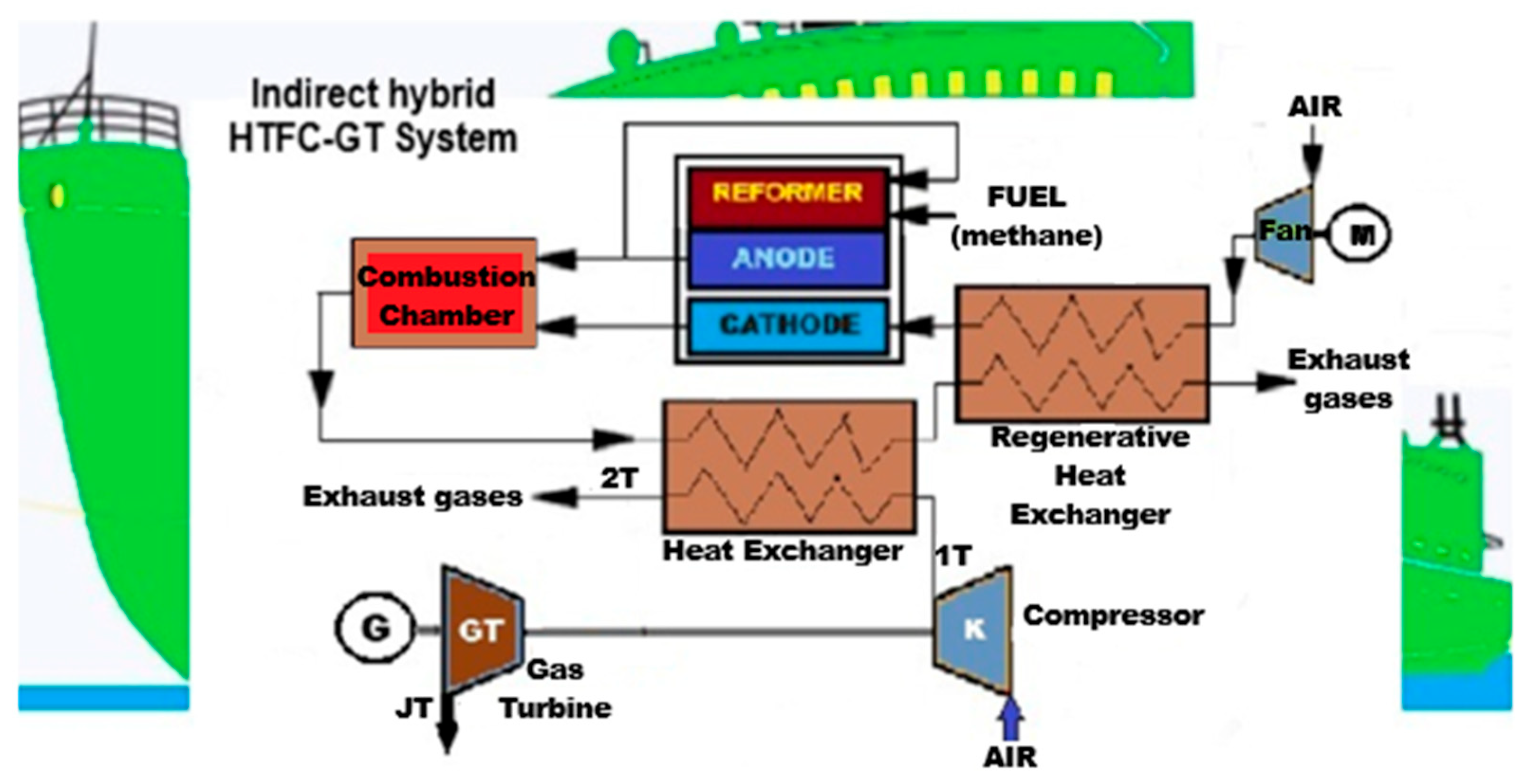
3.3. Hybrid Energy Supply Systems with Fuel Cells and Gas Turbines

It is evident from the presentation of the types of fuel cells that MCFC and SOFC produce significant amounts of heat during operation, which can be utilised to enhance the efficiency of systems incorporating this type of fuel cell. In recent years, efficient hybrid systems consisting of gas turbines (GTs) and fuel cells (FCs) have been increasingly used for ship propulsion and for generating electricity on board ships. Such a hybrid system is practical; the thermodynamic connection of the gas turbine (GT) system with the fuel cell stack (FC), the additional heat source for the turbine assembly. The connection methods of these two systems separate them into direct and indirect systems. Several studies have been conducted on hybrid systems combining MCFC and SOFC, with the first attempt dating back to 2000 when Siemens Westinghouse developed a system featuring a 200 kW SOFC with an efficiency of 50%. The Japanese experimented with a 200kW system with an efficiency of 50.2%, subjecting it to 4000 h of continuous operation [68]. Among the most widely used fuel cells in marine applications are solid oxide fuel cells (SOFCs), and hybrid SOFC-GT system configurations can operate at both atmospheric and high pressures. Pressurised SOFC-GT systems, as designed and used, are compact and efficient and can generate higher powers at high GT pressures due to the increased SOFC voltage. However, system complexity, pressure differences at the anode and cathode, and the alignment of the SOFC and GT remain ongoing challenges. Ambient pressure SOFC-GT systems offer a wide range of GT options, as the GT pressure is independent of the SOFC pressure, and the GT pressure ratio does not impact the cell voltage. The results indicate that the pressurised system is more efficient than the ambient system, and the integration of SOFC with GT can be achieved through direct or indirect methods [66]. A hybrid cogeneration and power production (CHP) system is relevant because, overall, it outperforms the two systems that compose it: fuel cells (HT-PEM) and gas turbine (GT); in addition, the GT produces more auxiliary power than is necessary, further increasing the dynamic performance of the system, the power at the GT shaft can be used in the start-up phase to heat the HT-PEM, with the fuel mixture processor operating with a higher excess air to increase the amount of heat and electricity further. The best-performing commercial hybrid cogeneration systems based on SOFC have an electrical efficiency of 53–55%, with a thermodynamic efficiency of approximately 87% [69].
Direct hybrid gas turbine–fuel cell systems (Figure 8) were developed based on the Brayton cycle and mainly comprise HT-FCs, GT systems, (regenerative) heat exchangers, and some auxiliary equipment. Due to the costs of storage and transportation, high-temperature fuel cells such as SOFCs and MCFCs generally do not use pure hydrogen as a fuel for shipboard applications but rather a gaseous mixture containing hydrogen, resulting from the reforming of hydrocarbons (e.g., methane). As a working principle, the air is compressed in a compressor, preheated in a regenerative heat exchanger, and supplied to the fuel cell’s cathode. The fuel is reformed and fed to the anode for the electrochemical reaction. The unreacted fuel at the anode and the exhaust gases from the cathode are burned in the combustion chamber, with the heat generated driving the turbine shaft, compressor, and electric generator. Meanwhile, the exhaust gases from the turbine can be used to preheat the air (in some configurations, even the fuel) [67].
The direct system is limited by the GT’s mechanical characteristics, which restrict the operating range, whereas the indirect system can adjust the range by utilising a heat exchanger [68].
The indirect FC-GT system is a hybrid system in which the exhaust gas of the FC does not directly drive the GT. Figure 9 shows that the turbine is driven by the air heated by the combustion of the gases resulting from the anode and cathode. The compressed air drives the turbine before entering the fuel cell’s cathode, allowing “the fuel cell and gas turbine to operate independently, safely, and reliably”. However, for large-scale implementation of applications, the direct hybrid system is more attractive because the temperature at the turbine inlet is higher in the direct system. In contrast, the indirect system requires an additional combustion chamber before the turbine inlet [24,64]. On the other hand, the indirect integration of SOFC with GT allows the SOFC to operate at atmospheric pressure, which reduces the sealing requirements. Nevertheless, this configuration requires high temperatures and differential pressures for the heat exchanger to efficiently transfer heat between the fuel cell and the GT cycle [69].

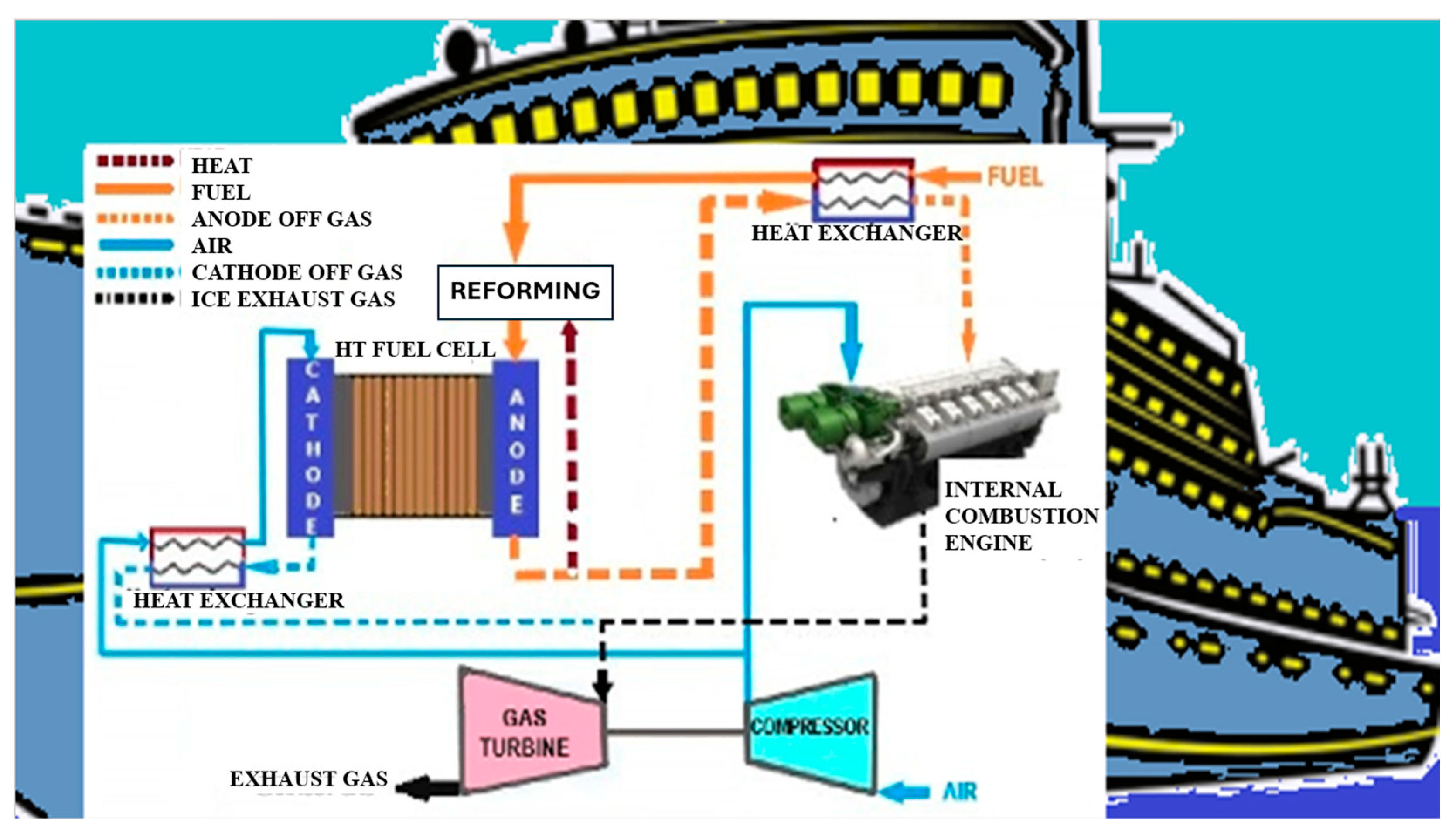
3.4. Hybrid Power Systems with Fuel Cells (FCs) and Internal Combustion Engine (ICE)

An interesting study used simulations and experiments to confirm that the use of a hybrid system comprising solid oxide fuel cells (SOFCs) combined with an internal combustion engine (ICE) can provide highly efficient electricity generation, increasing fuel utilisation (FU) and anode recycle percentage (ARP), leading to improved system performance [70]. The experiment and modelling of an SOFC-FC hybrid system concluded that the system with mixed gases (AOG-NG) was 3.55% more efficient at 70% fuel consumption. The most significant efficiency improvement of approximately 8%, concomitant with UHC/NOx emission reductions of roughly 43%/60%, was achieved at a SOFC-ICE power distribution of 67 ÷ 33% [71].
FC-ICE hybrid power systems can run on various fuels and respond quickly, making them potentially effective in reducing emissions in marine transport. Figure 10 shows the hybrid power system structure of a fuel cell–internal combustion engine. The “internal combustion engine is located downstream of the fuel cell” [24,70,71]. This system combines high-temperature fuel cells (HT-FCs) and gas turbines (GTs) to improve thermal efficiency and fuel consumption.
As a working principle, high-temperature fuel cells (HT-FC) are the first equipment to provide energy, and the waste gas from the anode and cathode contains a significant amount of heat. The anode exhaust gas is used to preheat the fuel entering the anode and to support fuel reforming. Then, the anode exhaust gas, rich in hydrogen, enters the combustion chamber of the internal combustion engine (ICE). At the same time, the cathode exhaust gas, after being preheated by the compressed air entering the cathode, together with the exhaust gas from the internal combustion engine, drives the gas turbine (GT) to produce compressed air. The gas turbine supplies the air required for the cathode of the fuel cells and the internal combustion engine. Unlike the previous two systems, the system is significantly more complex than it appears, as it involves multiple components and thermodynamic processes. Changes in the characteristics of an element or operating conditions can affect the system’s feasibility. The gas turbine is a component that must be closely matched to the system, and the correctness of its design parameters must be guaranteed. Otherwise, the system may not function properly, or its efficiency may not reach the ideal level. The SOFC-ORC hybrid system’s performance was rigorously evaluated through energy and economic analyses, which found a power generation efficiency of about 62% for the hybrid system, in which the SOFC has 73.5% of the power output share, according to [72]. The above considerations may indicate that hybrid FC-ICE systems are suitable for small- and medium-sized ships. Systems containing gas turbines are more appropriate for large vessels.
A. Benet et al. mention in their analysis that to achieve an appreciable level of flexibility regarding load demand, fuel cells need to be integrated with other energy sources installed on board ships, such as internal combustion engines, gas turbines, batteries, or capacitors, in generic hybrid marine fuel cell power plants (FCMHPPs). The study of specialised publications reveals that LNG has a higher rate of occurrence in large cruise ships than in passenger ships, with hydrogen attracting the most attention, and this is evidenced by the fact that PEMFCs tend to be studied in applications with lower installed power ranges, while SOFCs are chosen for higher power ranges. Also, PEMFCs require higher hydrogen purity, while SOFCs work very well with LNG. PEMFCs are most often hybridised with batteries [45].
To highlight hydrogen’s essential role in decarbonising the maritime industry, Table 8 analyses the use of hydrogen in maritime operations, including propulsion mechanisms, hybrid systems, and port infrastructure. It defines critical characteristics such as operational efficiency, emission reduction potential, associated challenges, and case studies, thus edifying the essential function of hydrogen in decarbonising the maritime industry [44].

4. Challenges of Maritime Safety Regulations

The IMO has published interim guidelines for the safety of ships using fuel cell power installations, marking a significant step towards global harmonisation of safety standards for hydrogen-fuelled vessels. These guidelines cover various aspects of vessel design, including fuel storage, fuel cell systems, electrical equipment, and emergency response. As a zero-emission fuel, hydrogen plays a crucial role in aligning the shipping sector with the IMO’s greenhouse gas reduction strategy, particularly its goal of reducing emissions by 50% by 2050. Regulatory frameworks such as the IMO’s GHG reduction strategy, the MARPOL Convention, regional policies, and the EU’s Emissions Trading System provide essential guidance and incentives for adopting hydrogen technologies. These regulations drive the integration of hydrogen fuel cells, the optimisation of ship designs for energy efficiency, and the development of hydrogen infrastructure, fostering a low-carbon transition in maritime transport. Ongoing regulatory advancements from the IMO and classification societies further enhance safety, technical feasibility, and operational reliability. Pioneering case studies, such as the “Viking Lady” and “Energy Observer” demonstrate the viability and potential of hydrogen as a clean energy source for maritime propulsion [73].
Regarding the safety of storage procedures, standards have been established for the industrial adoption of hydrogen, both for gaseous and liquid hydrogen. The International Organisation for Standardisation (ISO) has issued several guidelines related to the use of hydrogen, with ISO/TR 15916:2015 [74] being developed for the use of hydrogen in both gaseous and liquid forms. ISO 13984:1999 [75] and ISO 13985:2006 [76] are issued to guide the distribution of liquid hydrogen to vehicles and specify the requirements for liquid hydrogen tanks. In turn, Technical Committee (TC) 197 is involved in developing standards related to systems and devices used for hydrogen production, storage, transport, and measurement. As a safety tool, the separation distance (also known as safety distance) has been defined as the minimum separation distance between the source of danger and the object (including people) at which any effect of a probable and/or foreseeable incident can be avoided and prevent the spread of minor incidents [36]. Both hydrogen and ammonia have properties that introduce new safety risks, triggering the need for increased focus on safety in ship design, construction, and operation. However, the lack of specific mandatory international regulations for ships running on these fuels hinders their widespread adoption. With its latest white paper, DNV aims to support customers in implementing these fuels by providing increased predictability through classification rules and early dialogue with Flag Administrations. The paper also outlines the relevant safety challenges and considers the industry’s efforts to ensure safe adoption and operation of these fuels at sea. DNV is leading several initiatives to support the development and adoption of ammonia and hydrogen as marine fuels. These include the Nordic Roadmap for Future Fuels project, the Green Shipping Program, and the MarHySafe joint development project [77]. A gap analysis conducted by the study revealed that some current requirements of the IGF Code are unsuitable for hydrogen, and the structure itself needs to be revised to account for the specific characteristics of this fuel and related technologies. Furthermore, it emerged that transferring general technical requirements to the maritime sector is not straightforward, as implementing hydrogen systems on board ships requires identifying hazards that can be highly specific to different types of ships [78].
The Maritime Safety Committee has approved Interim Guidelines for the Safety of Ships Providing Fuel Cell Power Plants to ensure they are as safe and reliable as traditional oil-fuelled systems. These guidelines address multiple aspects, including the configuration, installation and maintenance of fuel cell power plants. Several feasibility studies have identified the hazards encountered on board ships with hydrogen propulsion systems and suggest various safety measures to address these risks [79]. Table 9 summarises some of the main hazards and safety measures involved.
The maritime industry is highly regulated, with all construction, maintenance, equipment and operations subject to strict rules and regulations developed by international bodies such as the International Maritime Organisation (IMO). These rules, which set global standards that all ships must comply with, are adopted into the national legislation of UN member states and enforced by classification societies through their own rules and regulations that ships must comply with. Some IACS classification societies have issued requirements for the storage and use of hydrogen as a fuel, which are mainly based on the IGF code. Although not directly related to the maritime industry, other international bodies and organisations, such as the International Organisation for Standardisation, the Compressed Gas Association, European Standards, etc., have also issued standards for equipment safety in hydrogen systems. These include safety rules, hydrogen storage rules, fuel system rules, and plant balance rules. Table 10 presents a list of these standards. However, the existing maritime regulatory framework, which is intended to cover all aspects of design, lacks cohesion. Hydrogen-related rules are incomplete, as they do not address important considerations and sometimes contain inaccuracies [80].

5. Conclusions

The present study reviews and analyses the literature on fuel cells with hydrogen. This review highlights the positive qualities and shortcomings of hydrogen production, storage, transportation, and utilisation in hybrid systems for marine and industrial applications.
Using comparative analyses, we highlighted the compatibility of hydrogen production and storage methods, as well as various types of fuel cells with marine applications, identifying cost and infrastructure constraints in the hydrogen value chain.
Extensive analysis of the use of hydrogen for maritime operations, including propulsion mechanisms, hybrid systems and port equipment, has highlighted the need for improved maritime safety regulations and standards.
Hydrogen could be produced in the future using relatively cheap hydrogen by-products from coastal industrial areas for use in marine applications. Producing hydrogen on board ships is a possible solution, as is using water electrolysis under the action of a form of renewable energy (wind or photovoltaic) or using excess energy from each system or residual thermal energy. Storage and transportation of hydrogen at sea are carried out by transport ships, generally in the case of liquid hydrogen, or by pipelines to transport compressed hydrogen. Since hydrogen is a zero-emission fuel and can be used with various propulsion technologies, it is a promising option for the maritime transport sector, meeting global decarbonisation goals.
The results of using proton exchange membrane fuel cell (PEMFC) technology in marine transport are not as satisfactory as the good results achieved in land transport. The problems encountered are related to the hydrogen supply chain and the challenging management of water and heat resulting from the low-temperature operating characteristics of PEMFC. The development of high-temperature proton exchange membrane fuel cell (HT-PEMFC) technology has made it more suitable for ships, as it is more tolerant to CO2 and simplifies the water management system. Moreover, the high-temperature characteristic enables heat recovery, making it a viable option for fuel cell ships. The other two types of high-temperature fuel cells (SOFC and MCFC) are suitable for fuel cell ships in development and experimentation, as they can utilise a higher volumetric density and fuels such as LNG and methanol, which have lower costs.
Currently, the primary types of hybrid marine hydrogen fuel cell systems are primarily used in on-board power systems, with less emphasis on propulsion systems. These systems combine energy storage with fuel cells, gas turbines with fuel cells, or internal combustion engines with fuel cells. The gas turbine can be utilised as a heat recovery device. A hybrid system combining high-temperature fuel cells and a gas turbine can significantly enhance the system’s efficiency if the energy management system is optimised. Research into hydrogen production from renewable sources, utilising excess energy from systems or residual thermal energy on board ships, is essential as a future direction. Additionally, developing technologies for storing, transporting, and utilising liquid hydrogen is crucial to support marine fuel cell applications.
Another research direction to investigate is the development of methods for modelling and simulating fuel cell systems (including hybrid systems) and optimising their control systems.

Author Contributions

Conceptualisation, writing—original draft preparation, S.-M.E.; writing—review and editing, S.B. All authors have read and agreed to the published version of the manuscript.

Funding

This research received no external funding.

Conflicts of Interest

The authors declare no conflicts of interest.

Abbreviations

The following abbreviations are used in this manuscript:
AEMAlkaline Anion Exchange Membrane
ARPAnode Recycle Percentage
ATRAutothermal Reforming
AWEAlkaline Water Electrolysis
CCS Carbon Capture and Storage
CCUSCarbon Capture, Utilisation, and Storage
CFRPCarbon Fibre-Reinforced Plastic
CGH2Compressed Gaseous Hydrogen
CHECargo Handling Equipment
FCFuel Cell
FCMHPPsHybrid Marine Fuel Cell Power Plants
GHGGlobal Greenhouse Gas
GTGas Turbine
HDVHeavy-Duty Vehicle
HESHydrogen Energy Storage
HTHigh Temperature
ICEInternal Combustion Engine
LIBLithium-Ion Battery
LNGLiquefied natural gas
LOHCLiquid Organic Hydrogen Carrier
LTLow Temperature
MCFCMolten Carbonate Fuel Cell
OGVOcean-Going Vessel
PEMProton Exchange Membrane
PEMFCProton Exchange Membrane Fuel Cell
POXPartial Oxidation
SMRSteam Methane Reforming
SOESolid Oxide Water Electrolysis
SOFCSolid Oxide Fuel Cell

References

  1. Reducing Barriers to Maritime Fuel Projects Is Key to Decarbonising Shipping. 2024. Available online: https://www.weforum.org/stories/2024/04/why-reducing-barriers-for-maritime-fuel-projects-is-key-to-progressing-on-decarbonization (accessed on 15 June 2025).
  2. Echim, S.; Budea, S. Applications of hydrogen energy in the field of transport. Int. Multidiscip. Sci. GeoConference SGEM 2024, 24, 39–46. [Google Scholar] [CrossRef]
  3. International Maritime Organisation (IMO). IMO Strategy on Reduction of GHG Emissions from Ships. 2023. Available online: https://www.imo.org/en/ourwork/environment/pages/2023-imo-strategy-on-reduction-of-ghg-emissions-from-ships.aspx (accessed on 15 June 2025).
  4. Fourth IMO Greenhouse Gas Study. International Maritime Organisation 2020. Published in 2021 by the IMO, London SE1 7SR. Available online: www.imo.org (accessed on 13 December 2024).
  5. Li, J.; Xu, H.; Zhou, K.; Li, J.-Q. A review on the research progress and application of compressed hydrogen in the marine hydrogen fuel cell power system. Helion 2024, 10, e25304. [Google Scholar] [CrossRef] [PubMed]
  6. DNV Hydrogen Forecast to 2050, Energy Transition Outlook 2022. Available online: https://aben.com.br/wpcontent/uploads/2022/06/DNV_Hydrogen_Report_2022_Highres_single1.pdf (accessed on 15 May 2025).
  7. Decarbonising Maritime: Overcoming Challenges with Innovation and Ingenuity, DNV Maritime Impact. 2024. Available online: https://www.dnv.com/expert-story/maritime-impact/decarbonizing-maritime-overcoming-challenges-with-innovation-and-ingenuity/ (accessed on 15 June 2025).
  8. Hora, C.; Dan, F.C.; Rancov, N.; Badea, G.E.; Secui, C. Main Trends and Research Directions in Hydrogen Generation Using Low Temperature Electrolysis: A Systematic Literature Review. Energies 2022, 15, 6076. [Google Scholar] [CrossRef]
  9. Boretti, A.; Banik, B.K. Advances in Hydrogen Production from Natural Gas Reforming. Adv. Energy Sustain. Res. 2021, 2, 2100097. [Google Scholar] [CrossRef]
  10. Ozcan, H.; El-Emam, R.S.; Horri, B.A. Thermochemical looping technologies for clean hydrogen production –Current status and recent advances. J. Clean. Prod. 2023, 362, 135295. [Google Scholar] [CrossRef]
  11. Badawi, E.Y.; Elkharsa, R.A.; Abdelfattah, E.A. Value proposition of bio-hydrogen production from different biomass sources. Energy Nexus 2023, 10, 100194. [Google Scholar] [CrossRef]
  12. Jiao, H.; Tsigkou, K.; Elsamahy, T.; Pispas, K.; Sun, J.; Manthos, G.; Schagerl, M.; Sventzouri, E.; Al-Tohamy, R.; Kornaros, M.; et al. Recent advances in sustainable hydrogen production from microalgae: Mechanisms, challenges, and future perspectives. Ecotoxicol. Environ. Saf. 2024, 270, 115908. [Google Scholar] [CrossRef] [PubMed]
  13. Shanmugaratnam, S.; Ravirajan, P.; Shivatharsiny, Y.; Velauthapillai, D. Green hydrogen production through photocatalytic seawater splitting on MS2/TiO2 nanocomposites over simulated solar irradiation. Int. J. Hydrogen Energy 2024, 91, 673–682. [Google Scholar] [CrossRef]
  14. Oh, V.B.Y.; Ng, S.F.; Ong, W.J. Is photocatalytic hydrogen production sustainable? Assessing the potential environmental enhancement of photocatalytic technology against steam methane reforming and electrocatalysis. J. Clean Prod. 2022, 379, 134673. [Google Scholar] [CrossRef]
  15. Franco, A.; Giovannini, C. Recent and Future Advances in Water Electrolysis for Green Hydrogen Generation: Critical Analysis and Perspectives. Sustainability 2023, 15, 16917. [Google Scholar] [CrossRef]
  16. Nemitallah, M.A.; Alnazha, A.A.; Ahmed, U.; El-Adawy, M.; Habib, M.A. Review on techno-economics of hydrogen production using current and emerging processes: Status and perspectives. Result Eng. 2024, 21, 101890. [Google Scholar] [CrossRef]
  17. IEA. Electrolysers. 2023. Available online: https://www.iea.org/energy-system/low-emission-fuels/electrolysers#overview (accessed on 10 July 2025).
  18. Chi, J.; Yu, H.M. Water electrolysis based on renewable energy for hydrogen production. Chin. J. Catal. 2018, 39, 390–394. [Google Scholar] [CrossRef]
  19. Erdemir, D.; Dincer, I. A new solar energy-based system integrated with hydrogen storage and heat recovery for sustainable community. Sustain. Energy Technol Assess 2022, 52, 102355. [Google Scholar] [CrossRef]
  20. About AEM Electrolysis. 2025. Available online: https://www.enapter.com/aem-electrolysis/ (accessed on 18 June 2025).
  21. Horizon’s New AEM Electrolyser Technology Brings the World Closer to $1/kg Green Hydrogen. Available online: https://www.einnews.com/pr_news/691547793/horizon-s-new-aem-electrolyser-technology-brings-the-world-closer-to-1-kg-green-hydrogen (accessed on 18 June 2025).
  22. Hygreen Energy Launches New AEM Electrolyser Systems. Available online: https://www.hygreenenergy.com/hygreen-energy-launches-new-aem-electrolyzer-systems/2024 (accessed on 18 June 2025).
  23. Dere, C.; Inal, O.B.; Zincir, B. Utilisation of waste heat for on-board hydrogen production in ships. Int. J. Hydrogen Energy 2024, 75, 271–283. [Google Scholar] [CrossRef]
  24. Fu, Z.; Lu, L.; Zhang, C.; Xu, Q.; Zhang, X.; Gao, Z.; Li, J. Fuel cell and hydrogen in maritime application: A review on aspects of technology, cost and regulations. Sustain. Energy Technol. Assess. 2023, 57, 103181. [Google Scholar] [CrossRef]
  25. Marefati, M.; Mehrpooya, M. Introducing a Hybrid Photovoltaic Solar, Proton Exchange Membrane Fuel Cell and Thermoelectric Device System. Sustain. Energy Technol Assess 2019, 36, 100550. [Google Scholar] [CrossRef]
  26. International Energy Agency. Global Hydrogen Review 2023. Available online: https://www.iea.org/reports/global-hydrogen-review-2023 (accessed on 15 May 2025).
  27. Alavi-Borazjani, A.S.; Adeel, S.; Chkoniya, V. Hydrogen as a Sustainable Fuel: Transforming Maritime Logistics. Energies 2024, 18, 1231. [Google Scholar] [CrossRef]
  28. Scarpati, G.; Frasci, E.; Ilio, G.D.; Jannelli, E. A comprehensive review on metal hydrides-based hydrogen storage systems for mobile applications. J. Energy Storage 2024, 102, 113934. [Google Scholar] [CrossRef]
  29. Van Hoecke, L.; Laffineur, L.; Campe, R.; Perreault, P.; Verbruggen, S.W.; Lenaerts, S. Challenges in the use of hydrogen for maritime applications. Energy Environ. Sci. 2021, 14, 815–843. [Google Scholar] [CrossRef]
  30. Samoilov, V.; Sultanova, M.; Borisov, R.; Lavrent’EV, V.; Ramazanov, D.; Egazar’YAnts, S.; Maximov, A. The production of a liquid organic hydrogen carrier (LOHC) and jet fuel fractions by hydroprocessing of pyrolysis fuel oil (PFO). Int. J. Hydrogen Energy 2024, 49, 1386–1400. [Google Scholar] [CrossRef]
  31. Makaryan, I.A.; Sedov, I.V.; Maksimov, A.L. Hydrogen Storage Using Liquid Organic Carriers. Russ. J. Appl. Chem. 2020, 93, 1815–1830. [Google Scholar] [CrossRef]
  32. Feki, I.; Shirinbayan, M.; Nouira, S.; Bi, R.T.; Maeso, J.-B.; Thomas, C.; Fitoussi, J. Composites in high-pressure hydrogen storage: A review of multiscale characterisation and mechanical behaviour. J. Pre-Proof 2024, 16, 100555. [Google Scholar] [CrossRef]
  33. Durbin, D.J.; Malardier-Jugroot, C. Review of hydrogen storage techniques for on-board vehicle applications. Int. J. Hydrogen Energy 2013, 38, 14595–14617. [Google Scholar] [CrossRef]
  34. Hafner, T.; Macher, J.; Brandstätter, S.; Trattner, A. Advancing hydrogen storage: Development and verification of a high-pressure permeation test setup for polymeric barrier materials. Int. J. Hydrogen Energy 2024, 96, 882–891. [Google Scholar] [CrossRef]
  35. Xing, H.; Stuart, C.; Spence, S.; Chen, H. Fuel Cell Power Systems for Maritime Applications: Progress and Perspectives. Sustainability 2021, 13, 1213. [Google Scholar] [CrossRef]
  36. Aziz, M. Liquid Hydrogen: A Review on Liquefaction, Storage, Transportation, and Safety. Energies 2021, 14, 5917. [Google Scholar] [CrossRef]
  37. Xu, X.; Xu, H.; Zheng, J.; Chen, L.; Wang, J. A high-efficiency liquid hydrogen storage system cooled by a fuel-cell-driven refrigerator for hydrogen combustion heat recovery. Energy Convers. Manag. 2020, 226, 113496. [Google Scholar] [CrossRef]
  38. Makepeace, J.W.; He, T.; Weidenthaler, C.; Jensen, T.R.; Chang, F.; Vegge, T.; Ngene, P.; Kojima, Y.; de Jongh, P.E.; Chen, P.; et al. Reversible ammonia-based and liquid organic hydrogen carriers for high-density hydrogen storage: Recent progress. Int. J. Hydrogen Energy 2019, 44, 7746–7767. [Google Scholar] [CrossRef]
  39. Spatolisano, E.; Pellegrini, L.A.; de Angelis, A.R.; Cattaneo, S.; Roccaro, E. Ammonia as a Carbon-Free Energy Carrier: NH3 Cracking to H2. Ind. Eng. Chem. Res. 2023, 62, 10813–10827. [Google Scholar] [CrossRef]
  40. Iulianelli, A.; Ribeirinha, P.; Mendes, A.; Basile, A. Methanol steam reforming for hydrogen generation via conventional and membrane reactors: A review. Renew Sustain. Energy Rev. 2014, 29, 355–368. [Google Scholar] [CrossRef]
  41. Svanberg, M.; Ellis, J.; Lundgren, J.; Landalv, I. Renewable methanol as a fuel for the shipping industry. Ren. Sust. Energy Rev. 2018, 94, 1217–1228. [Google Scholar] [CrossRef]
  42. Sánchez, A.; Blanco, E.C.; Martín, M. Comparative assessment of methanol and ammonia: Green fuels vs. hydrogen carriers in fuel cell power generation. Appl. Energy 2024, 374, 124009. [Google Scholar] [CrossRef]
  43. Nivedhitha, K.S.; Beena, T.; Banapurmath, N.R.; Umarfarooq, M.A.; Ramasamy, V.; Elahi, M.; Soudagar, M.; Agbulut, Ü. Advances in hydrogen storage with metal hydrides: Mechanisms, materials, and challenges. Int. J. Hydrogen Energy 2024, 61, 1259–1273. [Google Scholar] [CrossRef]
  44. Jayabal, R. Hydrogen energy storage in maritime operations: A pathway to decarbonization and sustainability. Int. J. Hydrogen Energy 2025, 109, 1133–1144. [Google Scholar] [CrossRef]
  45. Benet, Á.; Villalba-Herreros, A.; D’aMore-Domenech, R.; Leo, T.J. Knowledge gaps in fuel cell-based maritime hybrid power plants and alternative fuels. J. Power Sources 2022, 548, 232066. [Google Scholar] [CrossRef]
  46. Lipiäinen, S.; Sillman, J.; Vakkilainen, E.; Soukka, R.; Tuomaala, M. Hydrogen transport options for a large industrial user: Analysis on costs, efficiency, and GHG emissions in steel mills. Sustain. Prod. Consum. 2024, 44, 1–13. [Google Scholar] [CrossRef]
  47. Hunt, J.D.; Zakeri, B.; Nascimento, A.; Vasconcelos de Freitas, M.A.; Amorim Fdo, C.; Guo, F.; Witkamp, G.-J.; van Ruijven, B.; Wada, Y. Hydrogen balloon transportation: A cheap and efficient mode to transport hydrogen. Int. J. Hydrogen Energy 2023, 53, 875–884. [Google Scholar] [CrossRef]
  48. Hora, C.; Dan, F.C.; Secui, D.-C.; Hora, H.N. Systematic Literature Review on Pipeline Transport Losses of Hydrogen, Methane, and Their Mixture, Hythane. Energies 2024, 17, 4709. [Google Scholar] [CrossRef]
  49. Wang, Z. An Overview of the Key Technology of Renewable Energy Multi-Energy Complementary Hydrogen-Storage-Transport. Appl. Comput. Eng. 2025, 128, 53–58. [Google Scholar] [CrossRef]
  50. Kim, K.; Roh, G.; Kwag, K.; Hwang, P.-I. Economic study of hybrid power system using boil-off hydrogen for liquid hydrogen carriers. Int. J. Hydrogen Energy 2024, 61, 1107–1119. [Google Scholar] [CrossRef]
  51. Kawasaki Heavy Industries—2024 Report—On the Front Lines of Value Creation. Available online: https://global.kawasaki.com/en/corp/sustainability/report/2024/pdf/24_houkokusyo.pdf (accessed on 1 May 2025).
  52. Lanni, D.; Di Cicco, G.; Minutillo, M.; Cigolotti, V.; Perna, A. Techno-economic assessment of a green liquid hydrogen supply chain for ship refuelling. Int. J. Hydrogen Energy 2025, 97, 104–116. [Google Scholar] [CrossRef]
  53. Le, T.-H.; Tran, N.; Lee, H.-J. Development of Liquid Organic Hydrogen Carriers for Hydrogen Storage and Transport. Int. J. Mol. Sci. 2024, 25, 1359. [Google Scholar] [CrossRef] [PubMed]
  54. Semchukova, V.; Topolski, K.; Abdin, Z. Hydrogen technology for maritime applications: A review of challenges, opportunities, and lessons from the port authority of New York and New Jersey. Renew. Sustain. Energy Rev. 2025, 216, 115641. [Google Scholar] [CrossRef]
  55. Clean Hydrogen Partnership. Study on Hydrogen in Ports and Industrial Coastal Areas—Reports. 2023. Available online: https://www.clean-hydrogen.europa.eu/media/publications/study-hydrogen-ports-and-industrial-coastal-areas-reports_en (accessed on 1 May 2025).
  56. Elammas, T. Hydrogen fuel cells for marine applications: Challenges and opportunities. Int. J. Res. Adv. Eng. Technol. 2023, 9, 38–43. Available online: www.allengineeringjournal.in (accessed on 1 March 2025).
  57. Xing, L.; Xuan, J.; Das, P.K. Fuel Cell Fundamentals. In Fuel Cells for Transportation: Fundamental Principles and Applications; Elsevier: Amsterdam, The Netherlands, 2023. [Google Scholar] [CrossRef]
  58. Tronstad, T.; Åstrand, H.H.; Haugom, G.P.; Langfeldt, L. Study on the Use of Fuel Cells in Shipping. EMSA 2017. Available online: https://www.emsa.europa.eu/publications/item/2921-emsa-study-on-the-use-of-fuel-cells-in-shipping.html (accessed on 1 January 2025).
  59. FCW. Technologies Molten Carbonate Fuel Cell. Available online: https://fuelcellsworks.com/knowledge/technologies/mcfc (accessed on 13 September 2024).
  60. Baldi, F.; Moret, S.; Tammi, K.; Marechal, F. The role of solid oxide fuel cells in future ship energy systems. Energy 2020, 194, 116811. [Google Scholar] [CrossRef]
  61. Rubri-Hydrogen Fuel Cell Ship. 2024. Available online: https://www.hfsinopower.com/hydrogen-fuel-cell-ship-1?_gl=1*965899*_up*MQ..*_gs*MQ..&gclid=CjwKCAjwx8nCBhAwEiwA_z__02Gq7rGEvmqQqBcdRuX4LvRJoXlI2TJgdCzLoc8gW1qDf20K5deg5RoCNx0QAvD_BwE&gbraid=0AAAAA9l8QxnbRYsxJlYdUwBlBLVpnsnTg (accessed on 15 June 2025).
  62. Van Sickle, E.; Ralli, P.; Pratt, J.W.; Klebanoff, L.E. MV Sea Change: The first commercial 100% hydrogen fuel cell passenger ferry in the world. Int. J. Hydrogen Energy 2025, 105, 389–404. [Google Scholar] [CrossRef]
  63. Wang, Z.; Dong, B.; Wang, Y.; Li, M.; Liu, H.; Han, F. Analysis and evaluation of fuel cell technologies for sustainable ship power: Energy efficiency and environmental impact. Energy Convers. Manag. 2024, 21, 100482. [Google Scholar] [CrossRef]
  64. Fuel Cell Power Systems for Marine and Offshore Applications © 2023; American Bureau of Shipping: Spring, TX, USA, 2023.
  65. Broer, A.; Polinder, H.; van Biert, L. Polymer electrolyte membrane fuel cell degradation in ships—Review of degradation mechanisms and research gaps. J. Power Sources 2025, 640, 236678. [Google Scholar] [CrossRef]
  66. Sorlei, I.-S.; Bizon, N.; Thounthong, P.; Varlam, M.; Carcadea, E.; Culcer, M.; Iliescu, M.; Raceanu, M. Fuel Cell Electric Vehicles—A Brief Review of Current Topologies and Energy Management Strategies. Energies 2021, 14, 252. [Google Scholar] [CrossRef]
  67. RiverCell3, R&D Project Gets Underway. Available online: https://www.now-gmbh.de/en/news/pressreleases/rivercell3-rd-project-gets-underway/2024 (accessed on 21 March 2025).
  68. Kwaśniewski, T.; Piwowarski, M. Design analysis of hybrid Gas Turbine-Fuel Cell power plant in stationary and marine applications. Pol. Marit. Res. 2020, 27, 107–119. [Google Scholar] [CrossRef]
  69. Loreti, G.; Facci, A.L.; Ubertini, S. High-Efficiency Combined Heat and Power through a High-Temperature Polymer Electrolyte Membrane Fuel Cell and Gas Turbine Hybrid System. Sustainability 2021, 13, 12515. [Google Scholar] [CrossRef]
  70. Chuahy, F.D.F.; Kokjohn, S.L. Solid oxide fuel cell and advanced combustion engine combined cycle: A pathway to 70% electrical efficiency. Appl. Energy 2019, 235, 391–408. [Google Scholar] [CrossRef]
  71. Sapra, H.; Stam, J.; Reurings, J.; van Biert, L.; van Sluijs, W.; de Vos, P.; Visser, K.; Vellayani, A.P.; Hopman, H. Integration of solid oxide fuel cell and internal combustion engine for maritime applications. Appl. Energy 2021, 281, 115854. [Google Scholar] [CrossRef]
  72. Li, C.; Wang, Z.; Liu, H.; Guo, F.; Li, C.; Xiu, X.; Wang, C.; Qin, J.; Wei, L. Exergetic and exergoeconomic evaluation of an SOFC-Engine-ORC hybrid power generation system with methanol for ship application. Fuel 2024, 357, 129944. [Google Scholar] [CrossRef]
  73. Zhou, Z.; Tao, J. Hydrogen-powered vessels in green maritime decarbonisation: Policy drivers, technological frontiers and challenges. Front. Mar. Sci. 2025, 12, 1601617. [Google Scholar] [CrossRef]
  74. ISO/TR 15916:2015; Basic Considerations for the Safety of Hydrogen Systems. International Organization for Standardization: Geneva, Switzerland, 2015. Available online: www.iso.org/standard/56546.html (accessed on 19 June 2025).
  75. ISO 13984:1999; Liquid Hydrogen—Land Vehicle Fuelling System Interface. International Organization for Standardization: Geneva, Switzerland, 1999. Available online: www.iso.org/standard/23570.html (accessed on 19 June 2025).
  76. ISO 13985:2006; Liquid Hydrogen—Land Vehicle Fuel Tanks. International Organization for Standardization: Geneva, Switzerland, 2006. Available online: www.iso.org/standard/39892.html (accessed on 19 June 2025).
  77. DNV White Paper Guides Shipowners on Safe and Scalable Adoption of Ammonia and Hydrogen Fuels. 2025. Available online: https://www.dnv.com/news/dnv-white-paper-guides-shipowners-on-scalable-adoption-of-ammonia-and-hydrogen-fuels/ (accessed on 19 June 2025).
  78. Georgopoulou, C.; Di Maria, C.; Di Ilio, G.; Cigolotti, V.; Minutillo, M.; Rossi, M.; Sullivan, B.P.; Bionda, A.; Rautanen, M.; Ponzini, R.; et al. On the identification of regulatory gaps for hydrogen as maritime fuel. Sustain. Energy Technol. Assess. 2025, 75, 104224. [Google Scholar] [CrossRef]
  79. Zhaka, V.; Samuelsson, B. Hydrogen as fuel in the maritime sector: From production to propulsion. Energy Rep. 2024, 12, 5249–5267. [Google Scholar] [CrossRef]
  80. Brouzas, S.; Zadeh, M.; Lagemann, B. Essentials of hydrogen storage and power systems for green shipping. Int. J. Hydrogen Energy 2025, 100, 1543–1560. [Google Scholar] [CrossRef]
Figure 1. An on-board system for hydrogen production with water electrolysis [24].
Hydrogen 06 00050 g001
Figure 2. The diagram for the hybrid poly-generation system [25].
Hydrogen 06 00050 g002
Figure 3. Hydrogen production by technology, 2020–2022.
Hydrogen 06 00050 g003
Figure 4. Principal hydrogen storage methods [28].
Hydrogen 06 00050 g004
Figure 5. Schematic of the precooled Claude process.
Hydrogen 06 00050 g005
Figure 6. NH3 value chain as a hydrogen carrier [39].
Hydrogen 06 00050 g006
Figure 7. Block diagram of a modular FC hybrid power supply system.
Hydrogen 06 00050 g007
Figure 8. Direct hybrid HTFC-GT system [67].
Hydrogen 06 00050 g008
Figure 9. Indirect hybrid HTFC-GT system [69].
Hydrogen 06 00050 g009
Figure 10. Schematic diagram of the FC-ICE system.
Hydrogen 06 00050 g010
Table 1. Hydrogen production efficiency and costs.
Source Method Process Efficiency (%)Cost ($/kg)
Fossil fuel useHydrocarbon reformingSteam reforming74–852.27
Partial oxidation60–751.48
Autothermal reforming60–751.48
Use of renewable sourcesBiological Bio-photolysis of biomass10–112.13
Anaerobic fermentation of biomass60–802.57
Photofermentation of biomass0.12.83
ThermochemistryBiomass gasification30–402.05
Biomass pyrolysis35–501.7
Water decomposition Water thermolysis20–458.4
Water photolysis0.0610
Proton exchange membrane (PEM) water electrolysis65–804.96–8.12
Alkaline electrolyte (AE) water electrolysis70–804.8
Solid oxide electrolyte (SOE) water electrolysis903.63
Table 2. Comparison of the different technologies for hydrogen production in terms of strengths, constraints, prices, and technology readiness level (TRL).
TechnologyStrengthsConstraintsH2 Yield (g/kg Feedstock)ProductionCost
($/kg H2)
TRL
GasificationReusing industrial leftovers and forest waste efficiently converts a lot of plant material
without needing expensive oxygen for steam
gasification.
CO2 release, tar and char formation deactivate catalysts, and H2 is varied due to diverse biomass, high temperatures, catalyst regeneration needed, and costly reactors.40–1901.7–2.29
Steam
Methane
Reforming
Current industrial design does not need costly oxygen sources.CO2 release, high temperatures, and catalyst regeneration are required.40–1300.89
ElectrolysisElectrolysis yields pure hydrogen from water using electricity, typically from renewables, ensuring a clean energy output. Its scalability allows diverse applications, while adaptability to intermittent renewables supports grid stability. Moreover, on-site production minimises transportation needs, promising for decentralised energy solutions.
AWE and PEM technologies are commercially available. SOEC and AEM technologies are maturing.
Electrolysis demands substantial energy input, potentially impacting its overall carbon footprint, especially when renewable electricity is not readily available. High initial equipment costs, less-than-optimal efficiencies, and maintenance requirements may hinder cost-effectiveness. Scaling up electrolysis for large-scale hydrogen production might pose engineering and logistical challenges, affecting its widespread adoption.-3.5–107–9
Photo FermentationRecycling organic and biological waste thoroughly, with almost complete conversion of materials, at low temperature and pressure levels.Limited production and slow rate of H2, demanding a large surface area, requiring bacterial control, high energy needed for enzymes, and inefficient solar energy conversion.9–493.54
Dark
Fermentation
Recycling organic and biological waste, utilising fast-growing algal biomass, operating at low temperatures and pressures, and accommodating appropriate carbon sources.Limited production and slow rate of H2, high generation of by-products, requiring pre-treatment.4–442.35
PyrolysisCurrent industrial setup recycles forest residue and industrial waste, converting biomass into gas, bio-oil, and biochar in a versatile and straightforward process.CO2 release, tar and char formation, H2 variability from complex biomass, catalyst regeneration needed, and a costly reactor.25–652.1–3.17
Table 3. Comparison of the different technologies for hydrogen production in terms of technical and economic obstacles.
TechnologyEconomic
Obstacles
Technical
Obstacles
Way Forward
GasificationDue to the elevated temperature required, a large investment and operating cost are required.Corrosion, plugging, and catalyst deactivation. Inadequate commercialisation and product standardisationMembrane reactors need to integrate H2 production methods to increase the efficiency.
Steam
Methane
Reforming
Expenses incurred during the process of the Catalyst companies-The lower consumption cost and the catalyst’s lifetime offset the higher unit catalyst cost.
ElectrolysisThe charge of electricity accounts for up to 40–57% of the levelized cost of hydrogen.Combining the energy system and business operations is a significant barrier to large-scale technology deployment.To achieve minimal CO2 emissions, consider the electricity source’s carbon footprint. Various geographic areas and clever operation tactics can also cut costs.
Photo FermentationIncreased yield at a high energy cost-Metabolic engineering has the potential to compensate for the breakthrough in the biohydrogen process. The effects of nutrient limitation and substrate utilisation were studied to identify the chromosomal genes in microalgae responsible for increased hydrogen production. Photobioreactor development requires optimal design.
Dark
Fermentation
The cost of the substrate is the primary factor influencing the cost of biohydrogen.Proper bioreactor development, construction, operation, and regulationThe combination of dark and photo fermentation reduces feedback inhibition.
Table 4. Comparison of hydrogen production methods.
Production MethodHydrogen TypeKey Implications
Gasification of brown coal (lignite) or black coal (bituminous)Brown and Black HydrogenCarbon-intensive processes with high CO2 emissions.
Steam methane reforming (SMR)Grey
Hydrogen
High CO2 emissions; widely used but environmentally harmful.
Natural gas reforming with Carbon Capture and Storage (CCS)Blue
Hydrogen
Reduces CO2 emissions but still has pre-chain emissions; a transitional solution.
Methane pyrolysisTurquoise HydrogenLow-carbon, produces solid carbon; significant CO2 reduction compared to grey hydrogen.
Water electrolysis by renewable energyGreen
Hydrogen
Minimal CO2 emissions, sustainable; key solution for decarbonization.
Solar-powered electrolysis Yellow HydrogenRelies exclusively on sunlight; minimal emissions.
Nuclear-powered electrolysisPink
Hydrogen
Low-carbon alternative without weather dependency; with nuclear waste concerns.
Oil sands and water–gas shift reactionAqua
Hydrogen
Emission-free, avoids CO2 release; low-cost.
Biological processes (dark and photo-fermentation)BiohydrogenLow emissions; renewable when feedstock is sustainable.
Table 5. Hydrogen storage capacity of various metals.
MaterialsHydrogen Storage Capacity
MgH2 7.7 wt%
MgV 4.4 wt%
MgCo 3.9 wt%
TiCr1.2V0.86.7 wt%
MgNb2O56.9 wt%
MgCr2O35.9 wt%
MgFe3O42.5 wt%
MgPd3.0 wt%
0.65MgH2/0.35ScH24.2 wt%
Mg5Ni3La 5.50 wt%
Mg10Ni3La 5.16 wt%
Mg15Ni3La 4.60 wt%
Mg20Ni3La 4.51 wt%
Ag/TiO2/CNT 10.94 wt%
MgF2+SrH2 5.30 wt%
(MgF2+SrH2)/Gr 6.1 wt%
FeCoNi/GS 6.24 wt%
Zr0.6Y0.4Fe2 1.77 wt%
Mg0.55Ti0.20Si0.25 234 mAhg−1
Mg45Zr5Co5 425 mAhg−1
Mg50CO50 372 mAhg−1
Mg45Pd5CO50 379 mAhg−1
Mg2Ni 450 mAhg−1
Mg67Ni27Nb4 273 mAhg−1
Mg0.8Al0.2Ni 350 mAhg−1
Mg67Ni27Nb1Al5 339 mAhg−1
Mg1.75Nb0.25Ni 600 mAhg−1
Table 6. Comparative analysis of hydrogen storage technologies.
Storage TechnologyCompressed Gas StorageCryogenic Liquid StorageSolid-State StorageAdsorption-Based StorageAmmonia-Based Storage
Volumetric Capacity (g/L)10–15 g/L~8 MJ/L100–130 g/L20–50 g/L50–60 g/L
Gravimetric Capacity (wt%)1–2%2–3%1–1.5%0.5–1.5%10–12%
Pressure/Temperature RequirementsUp to 700 bar−253 °C0.1–5 MPa, ambient temperatureLow pressure, cryogenic temperaturesAmbient pressure, mild temperatures
Energy DensityLow (~10 MJ/m3)HighMediumMediumMedium
Safety FeaturesHigh-pressure vessel neededAdvanced cryogenic insulationChemically stable materialsSpecial adsorbent materialsRequires controlled ammonia handling
Approximate Cost$500–$1000/kg H2$1500–$3000/kg H2$2000–$5000/kg H2$1000–$2000/kg H2$700–$1500/ kg H2
Application SuitabilityShort-distance transportLong-distance transportCompact storage for vehiclesPortable energy systemsEnergy carriers for transport and storage
Table 7. Parameters of various fuel cells and possibilities applications in ships.
Type of FCFuelsElectrodeTemperature (°C)Life Span (h)Power Density (W/cm2)Specific Power (W/kg)Fuel Economy ($/nm)Possibilities Applications
AFCH2Pt/Ag Pt/Ni60–20010,0000.5–1.035–1053.04Employ potassium hydroxide as the electrolyte to facilitate the conversion of hydrogen and oxygen into electrical energy and water, historically used in space applications
LT-PEMFCH2Pt/C Pt/C50–10060001.0–2.0300–10003.71Utilising hydrogen and oxygen to generate electrical energy and water
PAFCH2, LNG, MeOHPt/C Pt/C140–20010,0000.1–0.5100–2203.30Employ phosphoric acid electrolyte to convert hydrogen and oxygen into electrical energy and water, commonly found in stationary power generation setups
DMFCMeOHPt/C Pt-Ru/C 75–12060000.5–1.010–306.35Efficiently convert methanol fuel and oxygen into electricity and water without requiring hydrogen gas, commonly used in portable electronic devices
MCFCH2, MeOH, HydroxideLi/NiO Ni/Cr650–70015,0000.2–0.430–405.03Utilise molten carbonate electrolyte to transform hydrogen and carbon dioxide into electrical energy and water, suited for high-temperature applications such as large-scale power generation
SOFCH2, MeOH, Oxicarbide Sr/LaMnO3 Ni/YSZ 500–100020,0000.3–1.015–204.37Utilise a solid oxide electrolyte, functioning at temperatures above 600 ◦C to convert hydrogen and oxygen into electricity and water, noted for their efficiency and versatility
LNGFCLNGPt/C Pt 160–20010,0000.3–0615–203.97Harness liquefied natural gas as a fuel source, converting LNG and oxygen into electricity and water, with potential applications in clean transportation and power generation
HT-PEMFCH2Pt/C Pt/C150–20060000.9–1.8200–10004.10Employ proton exchange membrane and operate between 150 ◦C and 200 ◦C, effectively converting hydrogen and oxidant into electrical energy and water, offering specific advantages
BFCBiomassPt/Pd PB 80–100015,0000.5–1.010–304.66Utilise biomass-derived organic materials as fuel, converting biomass and oxidant into electricity and water, holding potential in renewable energy systems
Table 8. Marine hydrogen applications.
ApplicationHydrogen Fuel CellsHybrid Energy SystemsPort OperationsAuxiliary Power UnitsCargo Handling EquipmentHydrogen-Powered Tugboats
Efficiency (%)Up to 60%50–80%N/A40–70%N/AUp to 55%
Emissions Reduction (%)90% (GHGs)35% (efficiency gain)Up to 70%30–50%Up to 70%85%
Key ChallengesFuel supply and storageSystem complexityLimited infrastructureIntegration with existing systemsHigh initial investmentLimited refuelling facilities
ExampleMF hydra ferry, NorwayOffshore wind platformsHydrogen-powered cranesHydrogen backup power for cruise shipsHydrogen forklifts in portsHydrogen-powered harbour tugboats
Operational FeasibilityHigh for short-haul vesselsModerate, requires renewable integrationHigh but infrastructure-dependentModerate, dependent on ship typeHigh for large portsModerate for pilot-scale projects
Table 9. The potential hazards onboard a powered hydrogen vessel and potential safety measures.
Hazards OnboardSafety Measures
Potential hydrogen leaks in the Fuel Cell RoomDesignate Fuel Cell Room as a hazardous area. Install hydrogen detectors in areas prone to hydrogen leaks to trigger emergency shutdown systems. Implement air locks for access to the Fuel Cell Room. Implement continuous ventilation systems to prevent hydrogen accumulation in closed spaces. Ensure independent air ventilation for the Fuel Cell Room and fuel cells within it. Equip with hydrogen detectors for leak detection. Implement emergency shutdown (ESD) systems for automatic shutdown hydrogen supply. Validate hazardous area modifications through gas dispersion analyses. Adhere to the International Code of Safety for Ships (IGF Code) requirements. Incorporate additional structural fire protection fire detection and alarm capabilities.
Collision risks due to hydrogen storage tanksLocate hydrogen storage tanks at a safe distance from vessel sides as per IGF Code requirements. Consider special requirements for cryogenic LH2 storage.
Lack of specific and comprehensive rules governing hydrogenMeticulously design hazardous areas to avoid impacting critical vessel areas. Monitor regulatory updates and adapt installation practices and safety measures accordingly.
Installation of various electrical equipment on shipsAdhere to strict safety protocols for electrical equipment installations in hazardous zones. Ensure continuous validation of safety measures. Monitor regulatory updates and adapt safety measures accordingly.
Risk of spontaneous ignition from hydrogen release from the high-pressure manifold (CH2)Install protective steel plates between the hydrogen manifold and composite tanks.
Potential over-pressurisation of hydrogen tanks (CH2)Utilise pressure relief devices to prevent over-pressurisation in case of fire.
Risks associated with bunkering operationsImplement safety measures during bunkering operations, including pressure testing of the bunkering system. Follow best practices and guidelines for the safe transfer of hydrogen fuel during bunkering operations.
Table 10. Standards for equipment safety in hydrogen systems.
Standard NameStandard CodeIssued by
International Code of Safety for Ship Using Gases or Other Low-flashpointFuelsIGF CodeInternational Maritime Organisation
Hydrogen-fuelled shipsBV NR678Bureau Verittas
ABS Requirements for Liquefied Hydrogen Carriers-American Bureau of Shipping
ABS Requirements for Hydrogen Fuelled Vessels-American Bureau of Shipping
RINA Rules of Safety For Ships Using Hydrogen as a Fuel-RINA
LR Classification of Ships using Gases or other Low-flashpoint Fuels-Lloyd’s Register
Basic Considerations for the Safety of Hydrogen SystemsISO/TR 15916International Standardisation Organisation
Fuel cell road vehicles, Safety specifications, Protection against hydrogenhazards for vehicles fuelled with compressed hydrogenISO 23273International Standardisation Organisation
Road vehicles, Compressed gaseous hydrogen (CGH2) and hydrogen/naturalgas blends fuel system componentsISO 12619International Standardisation Organisation
Gaseous Hydrogen, Fuelling StationISO 19880International Standardisation Organisation
Hydrogen fuel qualityISO 14687International Standardisation Organisation
Hydrogen detection apparatusISO 26142International Standardisation Organisation
Fuel Cell TechnologiesISO IEC/TC 105International Standardisation Organisation
Safety Standard For Hydrogen And Hydrogen Systems Guidelines for HydrogenSystem Design, Materials, Selection, Operations, Storage and Transportation NASA
Standard for Cryogenic Hydrogen StorageCGA H-3Compressed Gas Association
Hydrogen Pipeline SystemsCGA G-5.6Compressed Gas Association/European IndustrialGases Association
Hydrogen Vent SystemsCGA G-5.5Compressed Gas Association
Hydrogen Piping and PipelinesASME B31.12American Society of Mechanical Engineers
Gaseous Hydrogen–Fuelling Stations—ValvesCSA HGV4.4CSA Group
Fuelling System GuidelineCSA HGV4.9CSA Group
Fuel cell technologiesBS EN 62282British Standards/European Standards
Proton Exchange Membrane Fuel CellSAC GB/T 20042Standardisation Administration of China
Proton exchange membrane fuel cell module for road vehiclesGB/T 33978China Fuel Cell Standards
Stationary fuel cell power systemsJIS C 62282Japanese Industrial Standards
Compressed Gases and Cryogenic Fluids CodeNFPA 55National Fire Protection Association
Disclaimer/Publisher’s Note: The statements, opinions and data contained in all publications are solely those of the individual author(s) and contributor(s) and not of MDPI and/or the editor(s). MDPI and/or the editor(s) disclaim responsibility for any injury to people or property resulting from any ideas, methods, instructions or products referred to in the content.

