Abstract
The International Maritime Organization (IMO) sets ambitious greenhouse gas reduction targets for the maritime industry. From a long-term net zero emission perspective, ammonia fuel is expected to play a significant role in the marine decarbonization journey compared to LNG as a transition fuel. Also, in addition to internal combustion engine applications, solid oxide fuel cells (SOFCs) have gained more attention in marine propulsion applications due to their high efficiency. This study was performed to investigate the technical feasibility of utilizing a closed-loop SOFC thermal energy release for ammonia decomposition, leading to hydrogen fuel generation and subsequently feed back into SOFCs. The result proves that the integrated system of ammonia cracking SOFCs can maintain a self-balanced condition, ensuring adequate SOFC heat supply for the ammonia cracking process to produce hydrogen while supporting normal SOFC operation and generating heat. This paper concludes that an integrated system represents a novel and feasible solution and emphasizes its potential as an adaptable solution for future marine applications.
1. Introduction
In 2018, the IMO initiated a greenhouse gas strategy that aims to reduce GHG emissions from international shipping and phase them out as soon as possible. In 2023, the strategy was revised and adopted with the goal of achieving net-zero emissions by 2050. Liquefied natural gas (LNG) has been determined to be the transitional fuel to aid in the decarbonization journey and decrease the usage of traditional marine fossil fuels [1]. Ammonia and hydrogen are the only viable fuels for achieving zero tank-to-wake emissions. In addition, ammonia has higher volumetric density compared to liquid hydrogen, resulting in reduced storage space requirements. For these reasons, ammonia is a promising marine fuel that will perform an important role as part of the long-term solution to achieve the decarbonization goal in the marine industry [2,3,4].
It is undeniable that the internal combustion engine has continued to be innovated over the past 100 years, and it is expected that the world’s first ammonia dual-fuel engine will be commercially available by as early as 2024 [5]. However, the internal combustion engine has reached its limits of energy efficiency. As a potential alternative option, the fuel cell system is gaining more attention for marine applications due to its vast potential [6,7]. Nonetheless, the poor reactivity of ammonia renders its direct use as a fuel in fuel cells inefficient, constituting a significant challenge that has impeded the advancement of ammonia-fueled fuel cell technology [8]. Ammonia cracking is well known as the best economical method to generate on-the-spot hydrogen gas for industrial applications [9]. Ammonia is decomposed in the ammonia cracker, which dissociates hydrogen and nitrogen. The hydrogen gas perfectly suits most of the fuel cell systems. However, the integrated process has not been explored in any research feasibility study. During the literature review of fuel cell technical feasibility studies, it was observed that the research mainly involved short sea-going vessels and coastal supply vessels [10,11,12,13], yachts [12], general cargo vessels [12], ROPAX vessels [7,12,14], small passenger ships [10,11,12,15], and tug-boats [12,13], and most of these research and projects used hydrogen as the preferable fuel for fuel cell system [16,17]. Due to its low volumetric density [18], it cannot be used for deep-sea operations as it would occupy a large space for bunker tanks [19].
Currently, many various fuel cell propulsion systems have been explored in the marine industry, mainly including Proton Exchange Membrane Fuel Cells (PEMFCs), molten carbonate fuel cells (MCFCs), and solid oxide fuel cells (SOFC) [20,21,22]. PEMFC technology is relatively mature and widely used in marine applications with moderate efficiency (42–50%) [23] and low operating temperatures (65–85 °C) [24]. However, it requires highly pure hydrogen [25], which will face challenges in the fuel supply chain when moving toward mass production [26]. Between SOFCs and MCFCs, SOFCs have an edge over MCFCs in being the more attractive option because of advancements in their technology, which have reduced manufacturing costs and improved reliability [27]. SOFCs have demonstrated exceptional efficiency, availability, noiselessness, less maintenance effort, and dependability, as well as relatively long-term durability, with great potential to be applied to merchant vessels in the future [28,29,30,31,32]. Although both ammonia and hydrogen can be utilized as fuel for SOFCs, hydrogen-fed SOFCs demonstrate higher efficiency than ammonia-fed ones [33].
Among current research papers that explore the application of SOFCs in marine applications, there is a notable gap in the literature regarding the integration of ammonia cracking and SOFC systems. Investigating the possibility of integrating ammonia cracking with SOFC systems in the marine industry could lead to a revolutionary propulsion solution, potentially transforming the field and disrupting the dominance of internal combustion engines in the merchant fleet. Along with the electricity generated by SOFCs, excess heat is also produced through chemical reactions. This surplus heat can be efficiently redirected to the ammonia cracker, where it aids in generating hydrogen fuel for the SOFCs, creating a closed-loop system through the endothermic process [34,35,36]. Therefore, the aim of this paper is to explore an innovative integration of ammonia cracking with SOFCs for marine propulsion, emphasizing its technical feasibility.
In this paper, a novel research gap in the integration of ammonia cracking and SOFC systems is first identified in the introduction. Secondly, the methodology of overall system integration is elaborated. Subsequently, the modeled system is validated by comparing it with available experimental data. Lastly, the result of the simulation is discussed prior to the conclusion.
2. Methodology
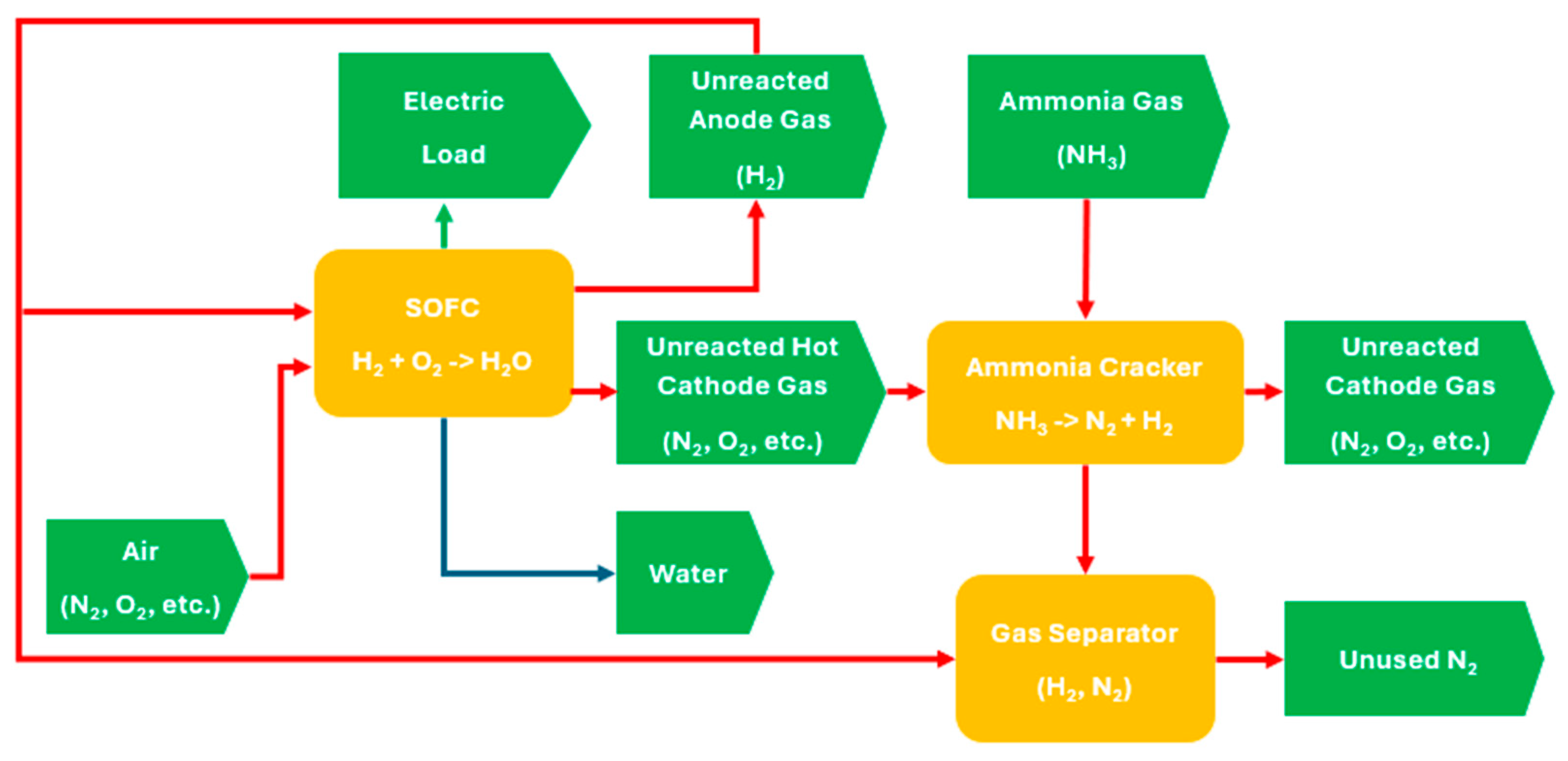
Figure 1 presents the overall working principle for an integrated ammonia cracker and SOFC system, where each red line represents a gas stream with input/output relationships; the green line represents an electrical stream, the blue line represents a liquid stream, rectangles symbolize individual components, and arrow pentagons denote specific inputs and outputs from/to components. Firstly, the ammonia gas (input) is supplied to a cracker for decomposition. To initiate the process, external heat, such as from a burner, is required to heat up the cracker. After the decomposition process, nitrogen and hydrogen (varied outputs) are produced through a catalytic reaction. After that, nitrogen is assumed to be filtered through a simplified membrane separator, with hydrogen retained and supplied to the anode inlet of SOFCs. Concurrently, air containing oxygen (input) is supplied to cathode inlet of SOFCs. Subsequently, the electrochemical reaction within the SOFCs generates various streams (varied outputs), including electricity, unreacted hydrogen, unreacted nitrogen, oxygen, and other gases with heat (varied outputs). The burner will cease heating the supply until sufficient heat is generated and equilibrium is reached under a static condition.
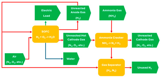
Figure 1.
Integrated system between ammonia cracking and fuel cell.
Under static conditions, the ammonia cracker and SOFCs can be considered two primary components of the integrated system. Here, the input parameters feeding the cracker include the flow rate of ammonia gas and heat derived from the SOFCs. The outputs, which include generated hydrogen gas from the cracker, unreacted hydrogen gas from the SOFCs, and air containing oxygen, are supplied to the SOFCs to produce both heat and electrical outputs. Details of the input and output of individual components are shown in Table 1.

Table 1.
Input and out of individual components.
In this study, ammonia cracking was simulated using the built-in model in gPROMS PROCESS. The ammonia cracking reaction formula is presented as NH3 → 3H2 + N2. The cracking of ammonia gas involves an endothermic process, with 92.44 kJ for each mol reaction. After the ammonia was heated, the ammonia molecules adsorbed on the active catalyst surface underwent gradual dehydrogenation. Subsequently, two adsorbed nitrogen atoms and two adsorbed hydrogen atoms combined to yield N2 and H2. The rate of the ammonia gas decomposition reaction can be expressed through the power law model, presented as follows.
Reaction rate of NH3:
RNH3 = k PNH3a PH2b PN2c
Kinetics constant calculation:
The porous catalytic bed of the ammonia cracker uses CoNi-Mgo as the reaction bed substrate, and the pre-exponential factor K0 is 9 × 10⁷ mol/m3s with a reaction activation energy Ea of 84 kJ/mol [37].
Heat transfer from SOFCs to ammonia cracker:
In addition to the ammonia cracker, a custom mathematical model of the SOFCs was developed using gPROMS Model Builder. This tailored single-cell SOFC model simulates the conversion of hydrogen and oxygen into electricity through a solid oxide electrolyte. The SOFC model depicted was comprised of multiple layers of materials, including anode, cathode, and electrolyte, positioned between two electrodes.
The model incorporated various parameters, such as electrochemical reactions and heat and mass transfer. The electrochemical reaction formula is presented as H2 + O2 → H2O.
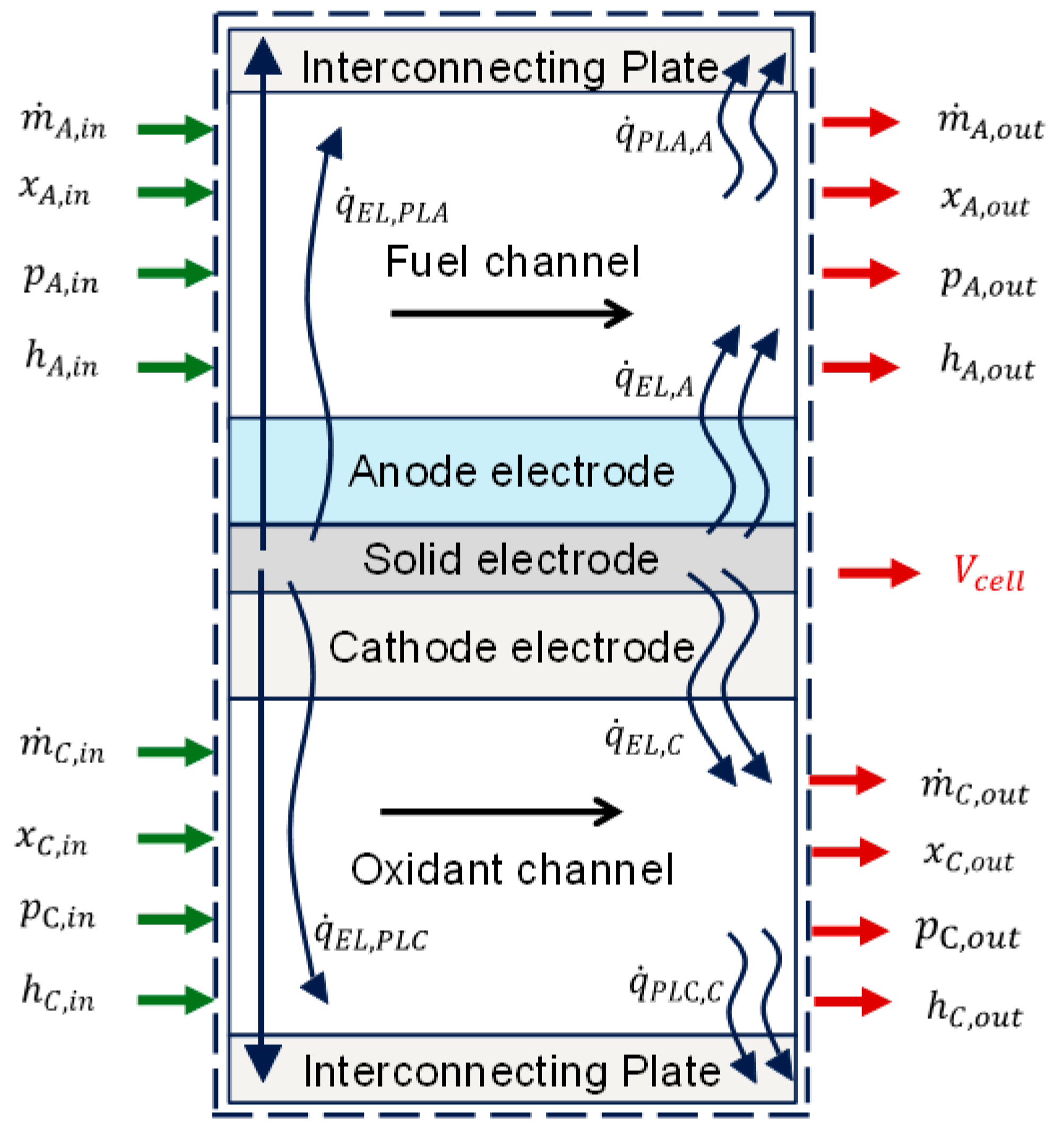
Figure 2 presents the reaction flow diagram adopted [38], with green arrows indicating inputs and red arrows representing outputs for developing model equations : is the mass flow rate in kg/s, P is the pressure in Pa, h is the specific enthalpy, x is the vector of the mole fraction of the species in the gas mixture, is the heat transfer rate within the fuel cell in kJ/s, and is the single-cell potential in V. The green arrows indicate inputs or specified variables, while the red arrows indicate outputs or calculated variables. A set of reaction equations are written below.
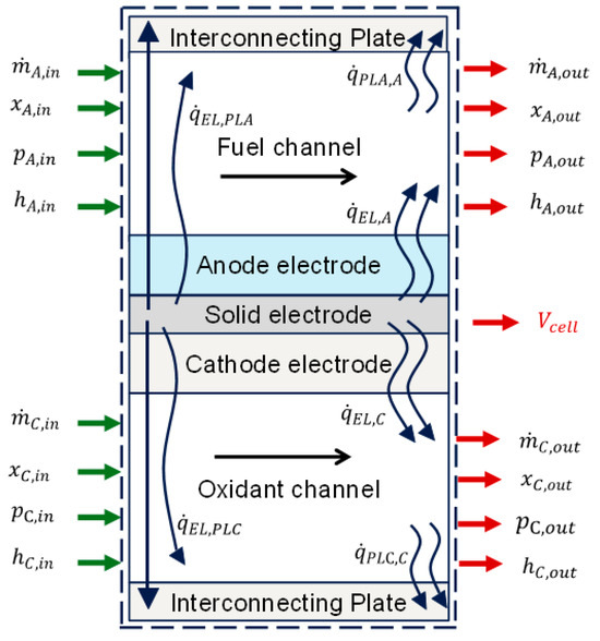
Figure 2.
Single-cell process diagram.
2.1. Electrochemical Reaction
Nernst’s potential, also referred to as the reversible potential, is the highest voltage that an ideal cell can achieve under specific operational circumstances. However, when an electric load is applied, there are numerous sources of irreversibility that diminish the ideal potential of the actual cell voltage. The voltage production expression includes open circuit term (ocv), ohmic overpotential (ohm), activation overpotential (act), and losses due to mass transport (conc), which can be calculated as follows.
The Gibbs’ free energy of the reaction determines the reversible cell potential (also known as open circuit voltage—ocv); the open circuit voltage is as follows:
The ohmic overpotential occurs as a result of the resistance to the conduction of electrons (via the electrodes) and ions (via the electrolyte). The ohmic overpotential is as follows.
Concentration overpotential occurs as a result of mass transport phenomena impacting the electrode reactions. This happens when the speed of the reaction and the rate of diffusion of reactants and products through the porous reaction site are comparable. The concentration overpotential is as follows.
The current density related to the activation overpotential is represented using the Butler–Volmer equation, as shown below.
The exchange current density j_0 is expressed below.
2.2. Mass and Heat Transfer Equation
The conservation equation for the chemical species is written in terms of the mass fraction of each species in the mixture. As for the mass conservation equation, the mass flux of oxygen is considered positive at the anode channel and negative at the cathode channel. A set of mass balance equations can be written as follows.
Mass conservation at anode and cathode:
The flow through the solid electrolyte is non-zero only for oxygen:
The anode channel experiences a positive mass flux of oxygen, while the cathode channel experiences a negative mass flux of oxygen as a result of the transfer of ions through the solid electrolyte.
Utilizing Faraday’s law, which establishes a connection between the reactant flux and the electric current generated within the fuel cell, allows us to determine the rate of the electrochemical reaction of hydrogen as r1.
In the energy conservation equation, the mass-specific enthalpy of the gas mixtures was employed, considering the enthalpy of formation of each component. The enthalpy of the hydrogen electrochemical oxidation reaction is deducted in the anode channel, as it is deemed to be released within the fuel cell.
At both anode, cathode, and solid electrolyte, the energy conservation equation can be written as follows.
Energy conservation at the anode:
Energy conservation at the cathode:
Energy conservation at the solid electrolyte:
Energy conservation at the fuel cell interconnecting plate:
2.3. Evaluation Metric
The performance of the system is evaluated in terms of fuel utilization, cell efficiency, air excess ratio, and electric power production, which are given as follows.
Fuel utilization:
Cell efficiency:
Air excess ratio:
Electric power production:
In the above-integrated system, the following assumptions are adopted:
- The 0D model is applied to ammonia cracking and SOFC systems.
- Only the static condition is evaluated and discussed.
- Assuming that all cells behave the same in the stack, a single-cell modular SOFC is used to represent the stack by considering the number of cells either in series and/or parallel arrangement. This would help simplify the assessment of the SOFC’s performance and capacity.
- The temperature difference within the electrolyte structure (anode and cathode electrolyte) is negligible.
- The transfer of heat between the electrolyte structure, the external surroundings, and between the SOFCs and ammonia crackers is not considered.
3. Validation
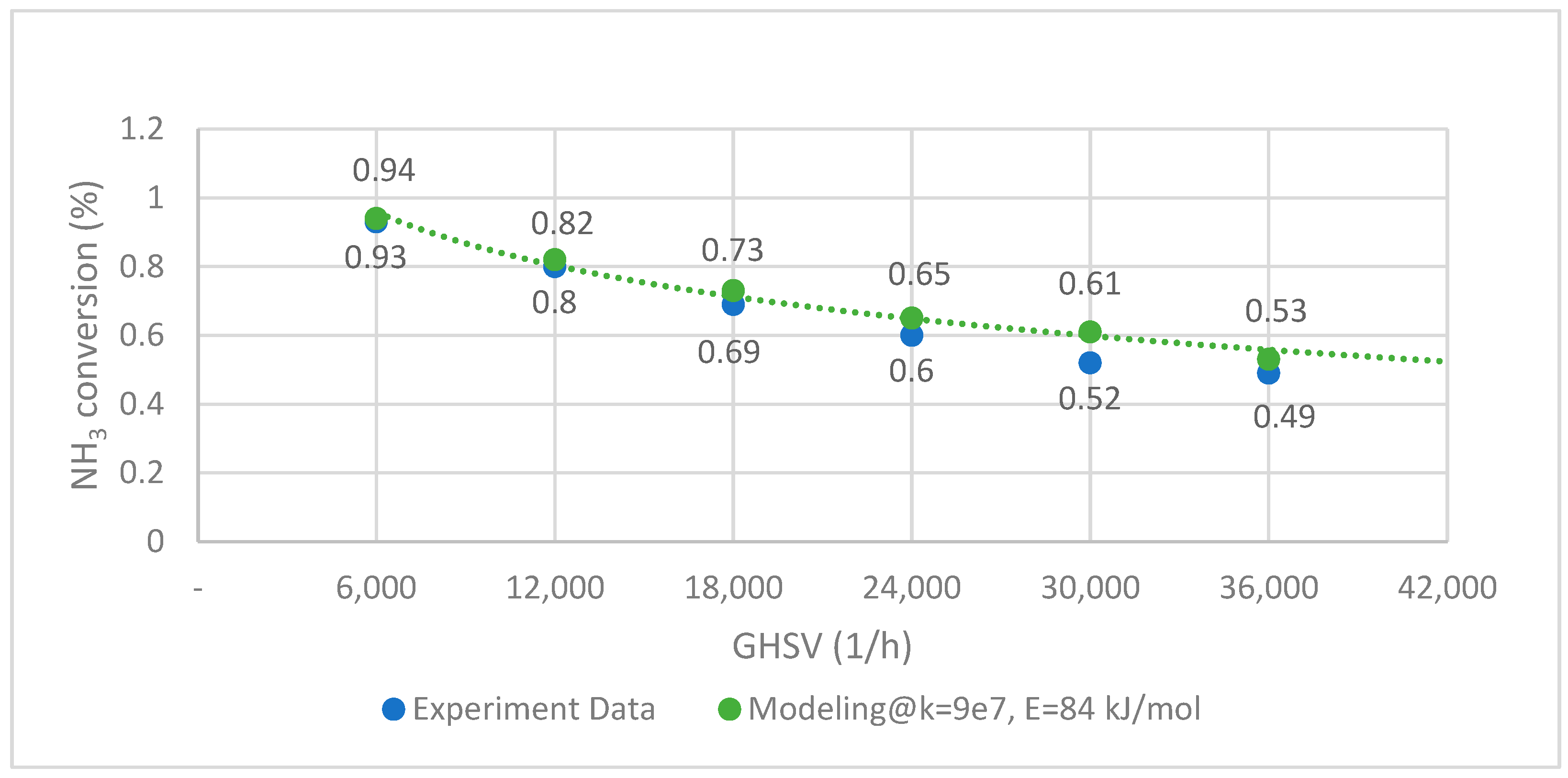
The ammonia cracking rate is determined by using experimental data from Han et al. with activation energy from Hassina et al. [38]. The fitted kinetics are then validated with various reaction conditions, as shown in Figure 3 below. The experimental test data are marked with blue dots, and the orange curve is the result of the numerical simulation. The data fitting accuracy is evaluated under the assumption that the root mean squared error (RMSE) is set at 0.049 and is found satisfactory.
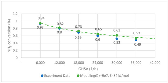
Figure 3.
NH3 decomposition curve of experimental data and modeling (CoNi-MgO @ 450 °C).
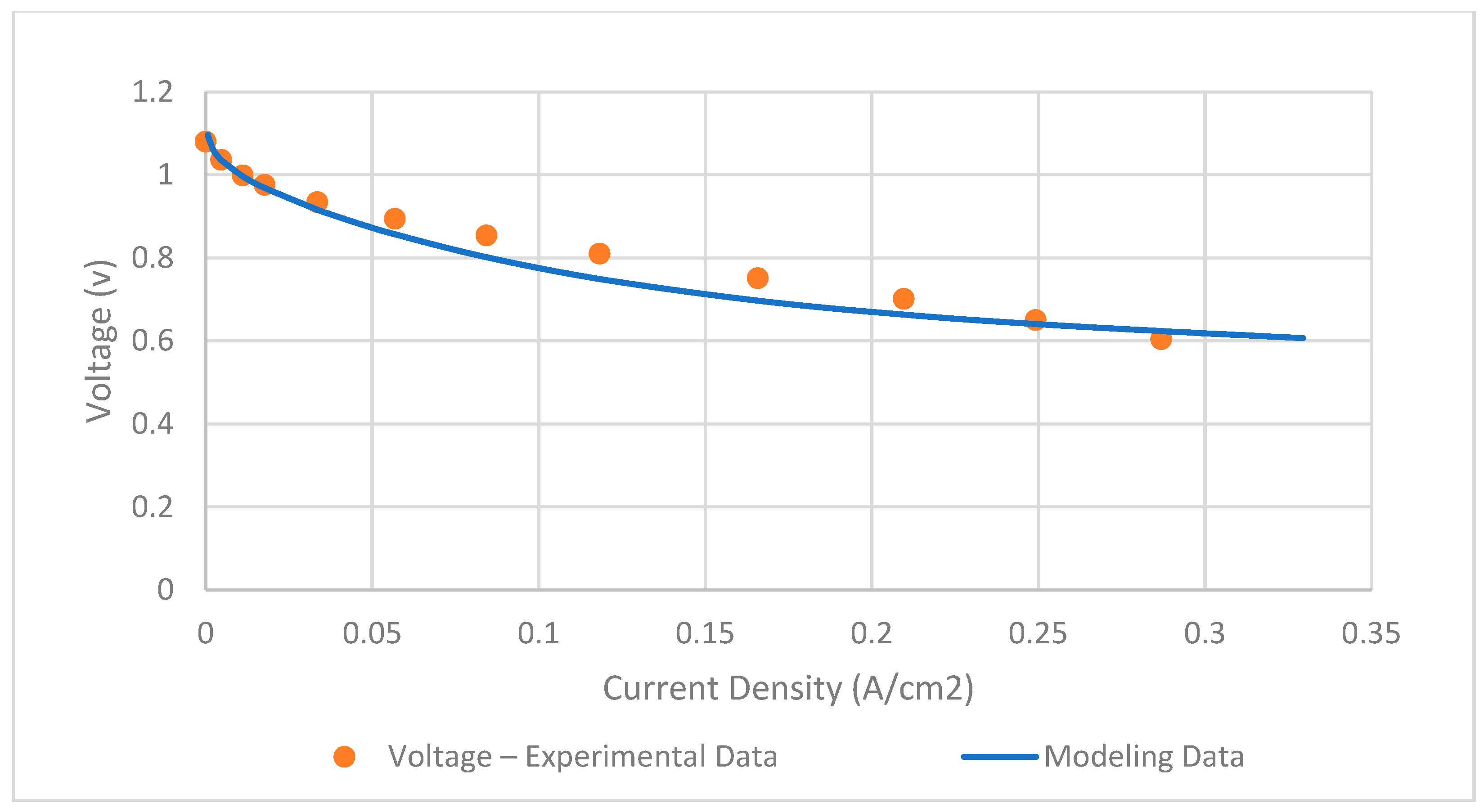
The SOFC model is validated by using real experimental data from Xu et al. [39]. The key input parameters of the SOFC model are presented in Table 2. By comparing the single-cell polarization curve depicted in Figure 4, it is observed that the RMSE is 0.03 and found to be accurate.

Table 2.
Main parameters of SOFC model.
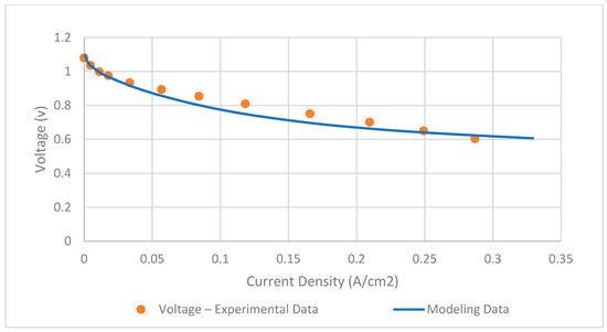
Figure 4.
Validation of SOFC model.
4. Result Evaluation and Discussion
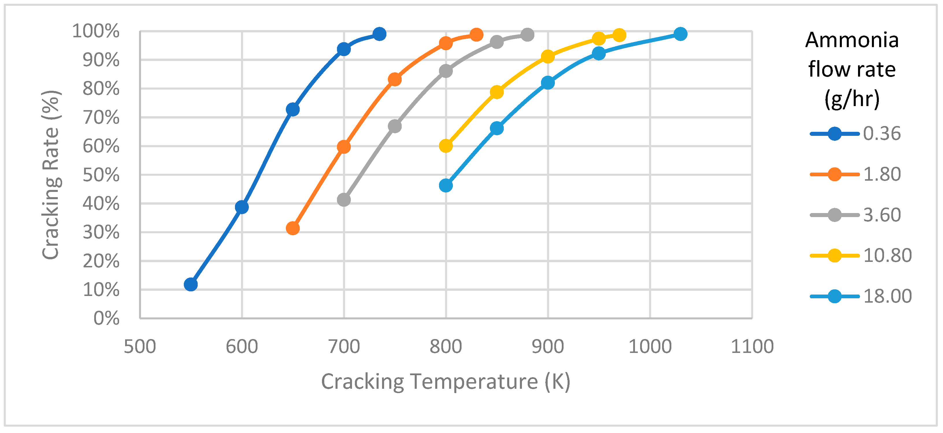
In the ammonia decomposition model, a tube-type cracker measuring 50 mm in length and 10 mm in diameter is designed. To evaluate how temperature affects ammonia cracking under various supply conditions, simulations are conducted at different flow rates, and the temperature versus cracking rate is plotted as shown in Figure 5. The decomposition process reveals that the temperature needed for optimal cracking rates changes with varying ammonia flow rates. A noticeable proportional trend can be observed between cracking temperature and cracking rate at different flow rates. For example, when supplying an ammonia flow rate of 0.36, 3.6, and 18 g/h at temperatures of 735, 880, and 1030 K, respectively, the cracking system demonstrates an impressive 99% decomposition rate. In principle, an increase in cracking temperature is accompanied by a progressive rise in the cracking rate, as the ammonia decomposition is an endothermic process. This correlation indicates that higher cracking temperatures positively influence the efficiency of the ammonia cracking process. The observed relationship between cracking temperature and cracking rate underscores the sensitivity of ammonia decomposition, providing crucial information for optimizing conditions in integration with fuel cell systems, where the efficiency of hydrogen production from ammonia is a pivotal consideration.
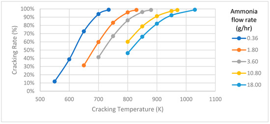
Figure 5.
Cracking temperature versus cracking rate.
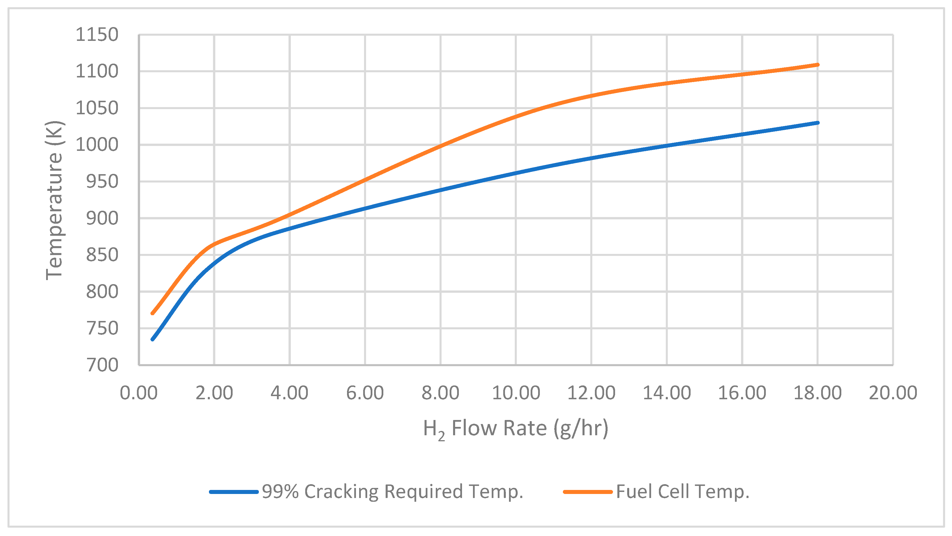
Also, to assess whether the temperature produced by the SOFCs is adequate for ammonia cracking, a comparison is made between the temperatures from the SOFCs and those required for ammonia cracking under an integrated system. It is observed that the temperature produced by SOFCs with varying hydrogen flow rates is adequate for achieving ammonia cracking at the maximum cracking rate of 99%, as indicated in Figure 6. This robust hydrogen output at a high level of cracking efficiency signifies the system’s ability to maximize the conversion of ammonia into hydrogen, minimizing waste and maximizing the yield of usable fuel.
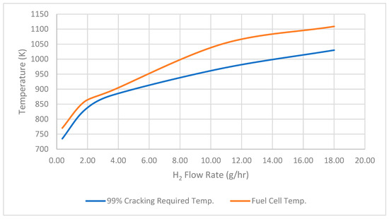
Figure 6.
Ninety-nine percent cracking required temp. versus fuel cell temp.
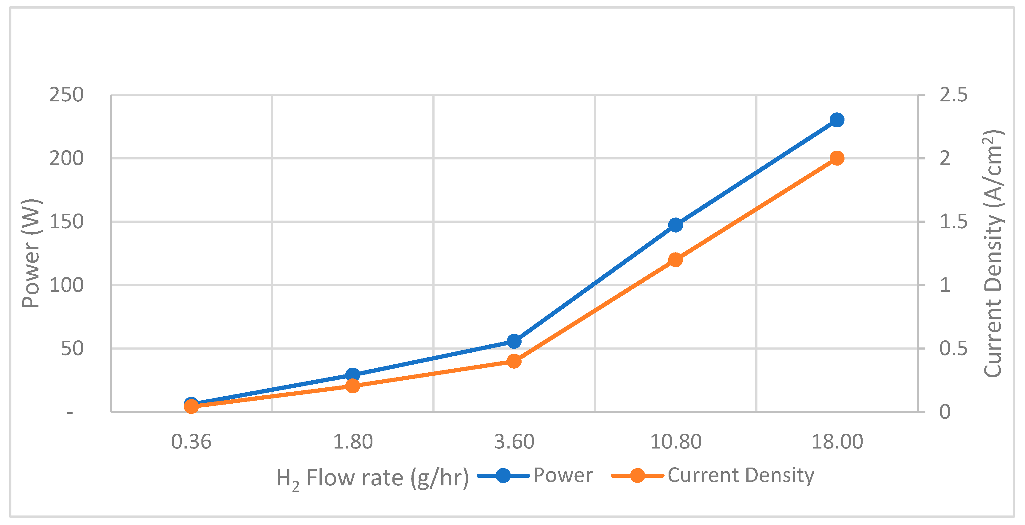
In the simulation of SOFCs, it is observed that with an increase in the flow rate of H2, there is a corresponding increase in both maximum power output and current density with a fixed inlet flow temperature at 700 K. Remarkably, the maximum power output and current density reach their peaks at 230 W and 2.0 A/cm2 when a flow rate supply of H2 to SOFCs is set at 18 g/h as shown in Figure 7.
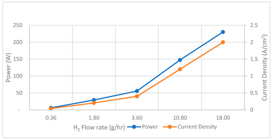
Figure 7.
SOFCs performance—H2 flow rate versus power and current density.
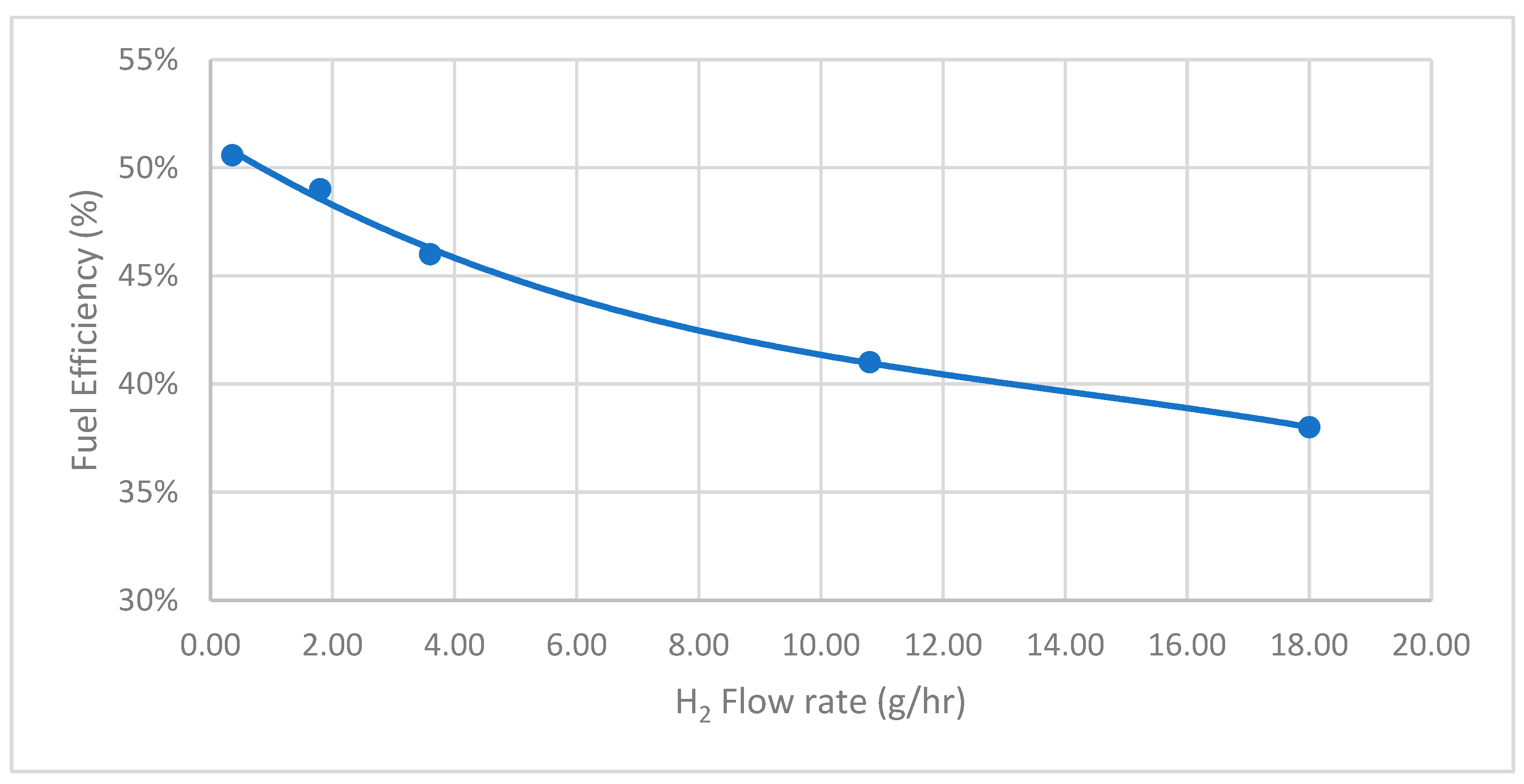
Fuel efficiency is another critical parameter for evaluating the system’s efficiency post-integration. It is observed that the fuel efficiency can achieve 51%, corresponding to the H2 flow rate at 0.36 g/h, as shown in Figure 8. However, as the flow rate increases, the fuel efficiency decreases, reaching approximately 38% at the highest tested flow rate. This inverse relationship suggests that while higher hydrogen flow rates enhance power output and current density, they may also lead to reduced fuel efficiency.
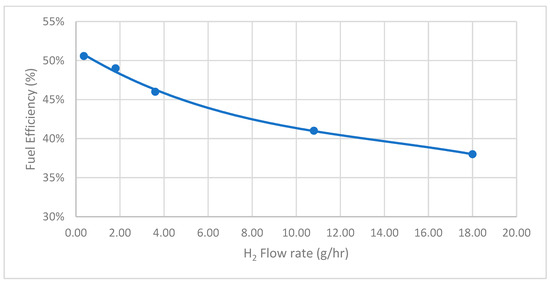
Figure 8.
SOFCs performance—H2 flow rate versus fuel efficiency.
These above observations highlight the need to balance hydrogen flow rate to optimize both power output and fuel efficiency in SOFC systems. Effective system design must consider the trade-offs between achieving higher power outputs and maintaining fuel efficiency to ensure overall system performance and sustainability.
Based on the result of various simulations performed, when achieving equilibrium with a specific rate of cracked hydrogen flow from the cracker supplied to the SOFCs, corresponding sufficient heat is generated for ammonia decomposition, resulting in diverse power output with corresponding efficiency. This is achieved through the integrated ammonia cracking-SOFC system, which proves the technical feasibility of utilizing a SOFC thermal energy release for ammonia cracking, facilitating hydrogen fuel production and backfeeding to SOFC for power generation.
5. Conclusions
The IMO greenhouse gas reduction targets have prompted the exploration of alternative fuels in the marine industry. Ammonia has emerged as a promising carbon-free marine fuel with its unique set of advantages [40]. To meet the decarbonization goals, fuel cells, particularly SOFCs, have gained attention for their high efficiency and potential compatibility with marine applications.
This paper explores the viability of the integration of ammonia cracking with SOFCs, which presents a novel solution for marine propulsion. This study emphasizes the technical feasibility of using a closed-loop SOFC system with up to 2 A/cm2 current density and 51% fuel efficiency to generate thermal energy release, resulting in a nearly 100% ammonia cracking rate to produce hydrogen fuel. The proposed system demonstrates impressive decomposition rates and power performance, highlighting its potential as an efficient and adaptable solution for marine applications. Given that the present simulation operates as a constant closed-loop model, the following research can extend to a dynamic simulation process from a cold start to a stabilization condition, thermal loss between SOFC sand ammonia crackers, and the study on improving the fuel efficiency without compromising the system performance.
Currently, the primary challenges hindering the widespread commercial and operational adoption of integrated ammonia cracking–SOFCs, notably issues such as heat transfer between SOFCs and ammonia crackers, miniaturization of integrated systems, volumetric power density, and lifespan for SOFCs, represent significant technological bottlenecks in the ammonia fuel cell technology sector to be resolved. Consequently, additional, comprehensive research is imperative to address these challenges, with a particular focus on energy efficiency optimization lifespan extension of SOFCs as a crucial aspect for industry advancement.
Author Contributions
Conceptualization, S.H.C. and S.W.; methodology, S.W.; software, S.W.; validation, S.H.C., B.M. and S.W.; formal analysis, B.M. and S.W.; investigation, S.H.C., B.M. and S.W.; resources, B.M. and S.W.; data curation S.W.; writing—original draft preparation, S.W.; writing—review and editing, S.H.C. and B.M.; visualization, B.M. and Wu S.W; supervision, S.H.C.; project administration, S.W. All authors have read and agreed to the published version of the manuscript.
Funding
This research is self-funded by S.W.
Data Availability Statement
The original contributions presented in the study are included in the article material, further inquiries can be directed to the corresponding author.
Acknowledgments
The authors wish to express their gratitude to the Singapore Maritime Institute for their generous funding support provided through the Maritime Transformation Programme, Project ID SMI-2023-MTP-02.
Conflicts of Interest
The authors declare no conflict of interest.
Nomenclature
| Specific heat capacity for electrolyte, kJ/kg-K | |
| Specific heat capacity for the anode, kJ/kg-K | |
| Specific heat capacity for the cathode, kJ/kg-K | |
| Activation energy of the reaction | |
| Energy of activation | |
| Total energy in the anode, kJ | |
| Total energy in the cathode, kJ | |
| F | Faraday constant, kJ/mol |
| Gibbs free energy, J/mol | |
| H | Height of channel, mm |
| Enthalpy of , kJ/kg | |
| Enthalpy of , kJ/kg | |
| Enthalpy of , kJ/kg | |
| Enthalpy of , kJ/kg | |
| Enthalpy of O2− | |
| Enthalpy of the O2− species crossing electrolyte, kJ/kg | |
| I | Current generated from the fuel cell through the electrochemical reaction from electrons |
| Component, e.g., H+, O2− | |
| J | Electrode current density, A/cm2 |
| Number of reactions | |
| Exchange current density, A/cm2 | |
| k | Thermal conductivity coefficient of the material, W/mK |
| Ko | Pre-exponential factor |
| Pre-exponential factor of the activation losses | |
| L | Length of single FC anode, m |
| Mass of electrolyte, kg | |
| Mass of anode, kg | |
| Mass of cathode, kg | |
| Mass flow rate in, kg/s | |
| Mass flow rate out, kg/s | |
| Mass flow rate in, kg/s | |
| Mass flow rate out, kg/s | |
| Mass flow rate in, kg/s | |
| Mass flow rate out, kg/s | |
| Mass flow rate of component i, kg/s | |
| Mass flow rate of component O2, kg/s | |
| Molecular weight of in-stream (including O2 and N2) entering the cathode side, kg/kmol | |
| Molecular weight of component i, kg/kmol | |
| Molecular weight of component O2, kg/kmol | |
| No. of mol of O2 entering the cathode side | |
| No. of mass fraction of hydrogen in the anode | |
| The power produced by the fuel cell, W | |
| Pressure of H2, bar | |
| Pressure of N2, bar | |
| Pressure of NH3, bar | |
| Partial pressure generated by the water in the anode, Pa | |
| Partial pressure generated by H2 in the anode, Pa | |
| Partial pressure generated by O2 in the anode, Pa | |
| Partial pressure generated by the water in triple phase boundary, Pa | |
| Partial pressure generated by H2 in triple phase boundary, Pa | |
| Partial pressure generated by O2 in triple phase boundary, Pa | |
| Partial pressure generated by O2 in the cathode, Pa | |
| Heat transfer rate from SOFC to ammonia cracker, kJ/s | |
| R | Universal gas constant, kJ/mol/K |
| RNH3 | Reaction rate in % |
| Rate of the electrochemical reaction of hydrogen | |
| Temperature for anode, K | |
| Temperature for the cathode, K | |
| Overall temperature for ammonia cracker, K | |
| Temperature for electrolytes, K | |
| Overall temperature for SOFC, K | |
| Temperature for electrode, K | |
| Temperature at anode, K | |
| Temperature at cathode, K | |
| Time, s | |
| Tortuosity of membrane between anode and electrolyte | |
| Tortuosity of membrane between cathode and electrolyte | |
| Tortuosity of membrane cross electrolyte | |
| V | Voltage generated from the fuel cell through the electrochemical reaction from electrons |
| Activation voltage losses, V | |
| Total cell voltage produced, V | |
| Open circuit voltage, V | |
| Ohmic voltage losses, V | |
| Voltage losses due to mass transport, V | |
| W | Width of single FC anode, m |
| Mass fraction for hydrogen at the anode | |
| Greek letters | |
| transfer coefficient | |
| Emissivity | |
| Stefan–Boltzmann constant, 5.67 × 10⁻⁸ J/(s × m2)/K4 | |
| Conductivity of the anode electrolyte layer | |
| Conductivity of the cathode electrolyte layer | |
| Conductivity of the electrolyte layer | |
| Heat transfer coefficient for the cathode, kJ/(s × m2 × K) | |
| Heat transfer coefficient for the anode, kJ/(s × m2 × K) | |
| Air excess ratio | |
| Heat transfer coefficient for SOFC, kJ/(s × m2 × K) | |
| Enthalpy of reaction 1 process, e.g., energy consumed from O2− to form H2O, J/mol | |
| Cell efficiency |
References
- Pompodakis, E.E.; Orfanoudakis, G.I.; Katsigiannis, Y.A.; Karapidakis, E.S. Hydrogen Production from Wave Power Farms to Refuel Hydrogen-Powered Ships in the Mediterranean Sea. Hydrogen 2024, 5, 494–518. [Google Scholar] [CrossRef]
- Chen, P.S.-L.; Fan, H.; Enshaei, H.; Zhang, W.; Shi, W.; Abdussamie, N.; Miwa, T.; Qu, Z.; Yang, Z. Opportunities and Challenges of Hydrogen Ports: An Empirical Study in Australia and Japan. Hydrogen 2024, 5, 436–458. [Google Scholar] [CrossRef]
- Inal, O.B.; Zincir, B.; Deniz, C. Investigation on the Decarbonization of Shipping: An Approach to Hydrogen and Ammonia. Int. J. Hydrogen Energy 2022, 47, 19888–19900. [Google Scholar] [CrossRef]
- Sørensen, R.D.; Berning, T. A Computational Fluid Dynamics Analysis of Hydrogen Leakage and Nitrogen Purging of a Solid Oxide Fuel Cell Stack. Hydrogen 2023, 4, 917–931. [Google Scholar] [CrossRef]
- Wartsila.com. Experience Wärtsilä 25 Ammonia, 4-Stroke Engine for Marine Applications. Available online: https://www.wartsila.com/marine/wartsila-25-ammonia (accessed on 25 July 2024).
- Elkafas, A.G.; Rivarolo, M.; Gadducci, E.; Magistri, L.; Massardo, A.F. Fuel Cell Systems for Maritime: A Review of Research Development, Commercial Products, Applications, and Perspectives. Processes 2022, 11, 97. [Google Scholar] [CrossRef]
- Xing, H.; Stuart, C.; Spence, S.; Chen, H. Fuel Cell Power Systems for Maritime Applications: Progress and Perspectives. Sustainability 2021, 13, 1213. [Google Scholar] [CrossRef]
- Jeerh, G.; Zhang, M.; Tao, S. Recent Progress in Ammonia Fuel Cells and Their Potential Applications. J. Mater. Chem. A 2020, 9, 727–752. [Google Scholar] [CrossRef]
- Ammonia Cracker. Available online: https://samgasprojects.com/detail/ammonia-cracker.html (accessed on 25 July 2024).
- Wang, Z.; Dong, B.; Yin, J.; Li, M.; Ji, Y.; Han, F. Towards a Marine Green Power System Architecture: Integrating Hydrogen and Ammonia as Zero-Carbon Fuels for Sustainable Shipping. Int. J. Hydrogen Energy 2024, 50, 1069–1087. [Google Scholar] [CrossRef]
- Welaya, Y.M.; El Gohary, M.M.; Ammar, N.R. A Comparison between Fuel Cells and Other Alternatives for Marine Electric Power Generation. Int. J. Nav. Arch. Ocean Eng. 2011, 3, 141–149. [Google Scholar] [CrossRef]
- Benet, Á.; Villalba-Herreros, A.; D’amore-Domenech, R.; Leo, T.J. Knowledge Gaps in Fuel Cell-Based Maritime Hybrid Power Plants and Alternative Fuels. J. Power Sources 2022, 548, 232066. [Google Scholar] [CrossRef]
- Díaz-de-Baldasano, M.C.; Mateos, F.J.; Núñez-Rivas, L.R.; Leo, T.J. Conceptual Design of Offshore Platform Supply Vessel Based on Hybrid Diesel Generator-Fuel Cell Power Plant. Appl. Energy 2014, 116, 91–100. [Google Scholar] [CrossRef]
- Di Ilio, G.; Bionda, A.; Ponzini, R.; Salvadore, F.; Cigolotti, V.; Minutillo, M.; Georgopoulou, C.; Mahos, K. Towards the Design of a Hydrogen-Powered Ferry for Cleaner Passenger Transport. Int. J. Hydrogen Energy 2024. In Press. [Google Scholar] [CrossRef]
- Dall’armi, C.; Micheli, D.; Taccani, R. Comparison of Different Plant Layouts and Fuel Storage Solutions for Fuel Cells Utilization on a Small Ferry. Int. J. Hydrogen Energy 2021, 46, 13878–13897. [Google Scholar] [CrossRef]
- Babatunde, O.M.; Akintayo, B.D.; Emezirinwune, M.U.; Olanrewaju, O.A. Environmental Impact Assessment of a 1 kW Proton-Exchange Membrane Fuel Cell: A Mid-Point and End-Point Analysis. Hydrogen 2024, 5, 352–373. [Google Scholar] [CrossRef]
- McKinlay, C.J.; Turnock, S.R.; Hudson, D.A. Route to Zero Emission Shipping: Hydrogen, Ammonia or Methanol? Int. J. Hydrogen Energy 2021, 46, 28282–28297. [Google Scholar] [CrossRef]
- Lamari, F.; Weinberger, B.; Langlois, P.; Fruchart, D. Instances of Safety-Related Advances in Hydrogen as Regards Its Gaseous Transport and Buffer Storage and Its Solid-State Storage. Hydrogen 2024, 5, 387–402. [Google Scholar] [CrossRef]
- Matveev, K.I.; Leachman, J.W. The Effect of Liquid Hydrogen Tank Size on Self-Pressurization and Constant-Pressure Venting. Hydrogen 2023, 4, 444–455. [Google Scholar] [CrossRef]
- Energy.gov. Comparison of Fuel Cell Technologies. Available online: https://www.energy.gov/eere/fuelcells/comparison-fuel-cell-technologies (accessed on 25 July 2024).
- Nanadegani, F.S.; Sunden, B. Review of Exergy and Energy Analysis of Fuel Cells. Int. J. Hydrogen Energy 2023, 48, 32875–32942. [Google Scholar] [CrossRef]
- Bielefeld, N.M.; Sørensen, R.D.; Jørgensen, M.; Kure, K.; Berning, T. A One-Dimensional Computational Model to Identify Operating Conditions and Cathode Flow Channel Dimensions for a Proton Exchange Membrane Fuel Cell. Hydrogen 2024, 5, 624–643. [Google Scholar] [CrossRef]
- Dudek, M.; Raźniak, A.; Markowski, J.; Danchak, L.; Dudek, P. The Energy Efficiency of an Extended Range Unit Involving a Polymer Exchange Membrane Fuel Cell Stack. E3S Web Conf. 2024, 551, 01010. [Google Scholar] [CrossRef]
- Tawalbeh, M.; Alarab, S.; Al-Othman, A.; Javed, R.M.N. The Operating Parameters, Structural Composition, and Fuel Sustainability Aspects of PEM Fuel Cells: A Mini Review. Fuels 2022, 3, 449–474. [Google Scholar] [CrossRef]
- Singh, M.; Zappa, D.; Comini, E. Solid Oxide Fuel Cell: Decade of Progress, Future Perspectives and Challenges. Int. J. Hydrogen Energy 2021, 46, 27643–27674. [Google Scholar] [CrossRef]
- Tellez-Cruz, M.M.; Escorihuela, J.; Solorza-Feria, O.; Compañ, V. Proton Exchange Membrane Fuel Cells (PEMFCs): Advances and Challenges. Polymers 2021, 13, 3064. [Google Scholar] [CrossRef]
- Micoli, L.; Coppola, T.; Turco, M. A Case Study of a Solid Oxide Fuel Cell Plant on Board a Cruise Ship. J. Mar. Sci. Appl. 2021, 20, 524–533. [Google Scholar] [CrossRef]
- Ilbas, M.; Kumuk, B.; Alemu, M.A.; Arslan, B. Numerical Investigation of a Direct Ammonia Tubular Solid Oxide Fuel Cell in Comparison with Hydrogen. Int. J. Hydrogen Energy 2020, 45, 35108–35117. [Google Scholar] [CrossRef]
- Stambouli, A.B.; Traversa, E. Fuel Cells, an Alternative to Standard Sources of Energy. Renew. Sustain. Energy Rev. 2002, 6, 295–304. [Google Scholar] [CrossRef]
- Yilmaz, F.; Ozturk, M. Design and Modeling of an Integrated Combined Plant with SOFC for Hydrogen and Ammonia Generation. Int. J. Hydrogen Energy 2022, 47, 31911–31926. [Google Scholar] [CrossRef]
- Kamara, K.P.; Merlin, G.; Bamba, G.; Druart, F.; Deseure, J. Simulation of Biogas Conversion Using Porous Solid Oxide Electrochemical Cells: Virtual Prototyping. Hydrogen 2022, 3, 488–500. [Google Scholar] [CrossRef]
- Peppas, A.; Kottaridis, S.; Politi, C.; Angelopoulos, P.M.; Taxiarchou, M. Multi-Model Assessment for Secondary Smelting Decarbonisation: The Role of Hydrogen in the Clean Energy Transition. Hydrogen 2023, 4, 103–119. [Google Scholar] [CrossRef]
- Ni, M.; Leung, M.K.H.; Leung, D.Y.C. Ammonia-Fed Solid Oxide Fuel Cells for Power Generation-A Review. Int. J. Energy Res. 2009, 33, 943–959. [Google Scholar] [CrossRef]
- Duong, P.A.; Ryu, B.; Kim, C.; Lee, J.; Kang, H. Energy and Exergy Analysis of an Ammonia Fuel Cell Integrated System for Marine Vessels. Energies 2022, 15, 3331. [Google Scholar] [CrossRef]
- Quach, T.-Q.; Giap, V.-T.; Lee, D.K.; Pineda, I.T.; Ahn, K.Y. Parametric Study of a High-Performance Ammonia-Fed SOFC Standalone System. J. Mech. Sci. Technol. 2022, 36, 3193–3201. [Google Scholar] [CrossRef]
- Cinti, G.; Liso, V.; Araya, S.S. Design Improvements for Ammonia-Fed SOFC Systems through Power Rating, Cascade Design and Fuel Recirculation. Int. J. Hydrogen Energy 2023, 48, 15269–15279. [Google Scholar] [CrossRef]
- Salogni, A.; Colonna, P. Modeling of Solid Oxide Fuel Cells for Dynamic Simulations of Integrated Systems. Appl. Therm. Eng. 2009, 30, 464–477. [Google Scholar] [CrossRef]
- Tabassum, H.; Mukherjee, S.; Chen, J.; Holiharimanana, D.; Karakalos, S.; Yang, X.; Hwang, S.; Zhang, T.; Lu, B.; Chen, M.; et al. Hydrogen Generation via Ammonia Decomposition on Highly Efficient and Stable Ru-Free Catalysts: Approaching Complete Conversion at 450 °C. Energy Environ. Sci. 2022, 15, 4190–4200. [Google Scholar] [CrossRef]
- Xu, Y.-W.; Wu, X.-L.; Zhong, X.; Zhao, D.; Fu, J.; Jiang, J.; Deng, Z.; Fu, X.; Li, X. Development of Solid Oxide Fuel Cell and Battery Hybrid Power Generation System. Int. J. Hydrogen Energy 2020, 45, 8899–8914. [Google Scholar] [CrossRef]
- MarineLink. Why Ammonia Is the Fuel of the Future for Maritime Shipping. Available online: https://www.marinelink.com/news/why-ammonia-fuel-future-maritime-shipping-506822 (accessed on 27 July 2023).
Disclaimer/Publisher’s Note: The statements, opinions and data contained in all publications are solely those of the individual author(s) and contributor(s) and not of MDPI and/or the editor(s). MDPI and/or the editor(s) disclaim responsibility for any injury to people or property resulting from any ideas, methods, instructions or products referred to in the content. |
© 2024 by the authors. Licensee MDPI, Basel, Switzerland. This article is an open access article distributed under the terms and conditions of the Creative Commons Attribution (CC BY) license (https://creativecommons.org/licenses/by/4.0/).

