Article

Gas Chromatography and Thermal Cycling Absorption Techniques for Hydrogen Isotopes Separation in Water Detritiation Systems

Fusion and Technology for Nuclear Safety and Security Department, ENEA, Via E. Fermi 45, 00044 Frascati, Italy
Hydrogen 2023, 4(3), 694-708; https://doi.org/10.3390/hydrogen4030044
Submission received: 14 July 2023 / Revised: 22 August 2023 / Accepted: 24 August 2023 / Published: 21 September 2023

Abstract

:
This work introduces state-of-the-art water detritiation processes and discusses the main technologies and materials adopted. Focus is given to the gas chromatography (GC) and the thermal cycling absorption process (TCAP), which are studied as potential back-end technologies for tritium recovery through a water detritiation system designed for a small-scale unit. GC and the TCAP are evaluated critically in order to establish their applicability for the final purification of the DT stream recovered at the bottom of the cryo-distillation column of a water detritiation unit. Both solutions (GC and the TCAP with an inverse column) exhibit safe and feasible operation modes and are characterised by a good technological level; furthermore, both of these processes meet the main design specifications required by the proposed application. However, the use of GC is preferred, since this system can operate with modest temperature cycling and producing streams (D2 and T2) of better purity.

1. Introduction

Water detritiation is required for the treatment of both processing and cooling water coming from fission and fusion nuclear plants. Depending on their flow rates and tritium levels, several strategies and processes for the treatment of tritiated water streams have been proposed. For low activity water, these treatments consist of direct disposal (e.g., release into rivers). In the case of higher tritium levels, the tritiated water is processed with the aim of producing concentrated tritium streams to be grouted and disposed of in burial sites or to be further processed to recover and valorise their tritium content.
Well-proven processes for the treatment of tritiated water use water distillation and water/gas catalytic exchange that, in turn, could be combined with electrolysis [1,2,3,4,5,6,7,8,9,10]. Although these processes are characterised by large energy consumption (heat and/or electricity), they rely on well-developed technology and have been applied worldwide in several plants.
The different affinity of materials with hydrogen isotopes is, in general, exploited for performing their separation. Numerous materials have been considered for taking advantage of such behavior in hydrogen isotopic separation. In practice, all metals and alloys exhibit a different selectivity in absorbing hydrogen isotopes according to the so-called “isotopic effect”. When the equilibrium pressure of hydrogen isotopes in gas and solid phases is pH2 > pD2 > pT2, a “normal isotopic effect” occurs, meaning that the heavier isotopes are preferably absorbed into the metal lattice. Conversely, if pT2 > pD2 > pH2, an “inverse isotopic effect” takes place and the protium is preferably absorbed in the metal [11,12]. The kind and intensity of the isotopic effect depends on the occupancy of the hydrogen atoms in the metal, i.e., the potential energy levels of the interaction between the hydrogen atoms and the lattice structure. For instance, a Pd alloy with Ag 25 wt.% at a low temperature and high pressure (high hydrogen/metal ratios) exhibits a normal isotopic effect that inverts at higher temperatures or lower pressures. Similar behavior is characteristic of the V–H and Ti–H systems [13].
Due to its high performance, Pd is largely adopted in units where a gaseous phase containing hydrogen isotopes comes into contact with the metal. The lighter hydrogen isotope is preferentially absorbed by the Pd; as a result, this isotope is enriched in the solid phase of the Pd while the heavier isotope is enriched in the gas phase [14,15,16].
Thanks to its easy and reliable realization, displacement chromatography using Pd-based materials is one of the techniques adopted for hydrogen isotope separation [17,18]. Further progress in hydrogen separation techniques has been made by the thermal cycling absorption process (TCAP), a concept invented at SRNL (Savannah River National Laboratory, USA) in 1980. It is a semi-continuous process in which the separation effect typical of displacement chromatography is enhanced by acting on the temperature; in fact, the isotopic effect increases as the temperature decreases [19,20].
This work contains a critical review of the gas chromatographic (GC) and thermal cycling absorption processes. After introducing water detritiation systems with a focus on hydrogen–material interactions, the expected effect of the main operating parameters on the isotopic separation properties is discussed. In particular, this work describes the gas chromatographic and thermal cycling absorption configurations presently adopted and validated in experimental campaigns. The aim is to assess their applicability as potential back-end technologies for tritium recovery carried out by a water detritiation system designed in the framework of the TITANS project [21]. In this contest, GC and TCAP are critically compared for the final separation of the deuterium-tritium stream that is extracted from the bottom of a cryo-distillation column of a water detritiation system.

2. Water Detritiation Technologies

Water detritiation technologies are needed for the treatment of the water coming from nuclear plants [1]; this water is generally characterised by low tritium concentrations (10 MBq/kg) and large volumes (more than 400 t/y per nuclear plant), corresponding to a throughput of around 500 kg/h.
Several approaches can be adopted for the extraction of tritium from tritiated water [22]. The disposal or treatment of tritiated water coming from nuclear plants has been analysed by considering their estimated costs and TRL [23]. When the resulting tritiated water concentration is below drinking water standards, there is no tritium separation and the tritiated water is directly released into rivers; in this case, the costs are limited to routine analyses and samplings (estimated 0.19 $/L). Grout disposal (using phosphate/sulfate waste grout) is another strategy that could be applied alone (estimated 3.2 $/L) or in combination with direct disposal to rivers.
The distillation of tritiated water employs a well-developed technology (TRL = 7); Chen et al. report the use of packed columns operating between 35 °C (top) and 43 °C (bottom) and 7 kPa of top pressure, as shown in Figure 1 and Figure 2 [1]. Water distillation can process the high throughputs typical of nuclear plants; however, it is characterised by fairly small separation factors and high energy consumption that lead to high estimated costs (5 $/L) [23,24].
Both VPCE (vapour-phase catalytic exchange) and LPCE (liquid-phase catalytic exchange) processes are based on isotopic exchange reactions involving hydrogen isotopologues in molecular (H2, D2, T2, HD, HT, DT) and oxidised forms (H2O, D2O, T2O, HDO, HTO, DTO). These processes are carried out in packed-bed columns where the tritiated water exchanges with hydrogen since the thermodynamic equilibrium of the hydrogen isotopic exchange reactions is shifted towards the oxidised compounds [25]. Both VPCE and LPCE processes have been developed to a good technological level (TRL = 7) but exhibit low separation factors, as shown in Table 1, corresponding to modest process decontamination factors (in the range 25–35).
High separation factors (H/T = 10 at 353 K) can be achieved by the treatment of tritiated water via electrolysis. The application of such a process is characterised by high operational costs and by safety concerns due to the risk of the recombination of oxygen with the tritiated gas; for these reasons, electrolysis is limited to the processing of high-activity water. Very high decontamination factors (30,000–50,000) at relatively low costs (estimated 1.9 $/L) can be achieved by the combination of electrolysis and LPCE in the CECE (combined electrolysis and catalytic exchange) process, as shown in Figure 3 [26]. In this case, the enriched tritium stream extracted from the bottom of an LPCE column is sent to an electrolyser by significantly reducing its electricity load.
Cryogenic distillation of hydrogen isotopes has also been adopted for hydrogen isotopic separation, and is typically carried out by packed columns under ambient pressure conditions [27]. It exhibits a good TRL (around 6), with costs estimated to be around 2.4 $/L [23].
In the water detritiation system of ITER (2006), the coupling of the CECE process with cryogenic distillation has been proposed. The first process is employed for detritiation and the second one is employed for tritium recovery, as shown in Figure 4 [28].
Electrolysis has also been proposed in combination with the thermal cycling absorption process (TCAP), another important process that will be described later in this work along with gas chromatography. When combined with TCAP, electrolysis exhibits TRL values of around 6 and costs of 4.5 $/L [23].

3. Materials for Hydrogen Isotopic Separation

The characteristic of some materials of absorbing hydrogen can be used to develop hydrogen isotopic separation processes. In particular, a different affinity of the hydrogen isotopes with the absorbent material makes the separation system more efficient.
Metals and metal alloys exhibit the capability of absorbing hydrogen and are therefore used to separate mixtures of its isotopes. The preferred material is palladium, which exhibits a very large hydrogen isotopic effect. In particular, the equilibrium pressures of the hydrogen isotopes over palladium are in the order of protium < deuterium < tritium, i.e., protium is more preferentially absorbed by the metal lattice than deuterium and tritium. This behavior is called the “normal isotopic effect” [15,20,29]. Among other materials, uranium has also been studied because it absorbs larger amounts of hydrogen than other metals [30]; however, the realization of isotopic separation systems based on uranium is limited by its modest separation performances. The absorption of hydrogen isotopes has been studied in intermetallic compounds as well; Yawny et al. measured the equilibrium pressure difference between deuterium and hydrogen for LaNi5 and Ti2Ni and demonstrated that the latter is more promising as an isotope-separation material [31]. Among other alloys of interest, Pd–Pt exhibits a heat of hydrogen solution lower than Pd and, therefore, can operate at room temperature with a low tritium inventory without requiring the use of any replacement gas for the desorption [32,33,34].
As mentioned above, due to its high performance, Pd is preferably adopted in most of the hydrogen isotopic separation systems. Its separation performances are strongly affected by the parameters influencing the interaction between the hydrogen isotopes and the solid phase (absorption material), specifically the gas–Pd contact area. In this view, Pd is prepared in the form of powders or deposited over small particles of a support material that are usually packed into separation columns. In several applications, porous kieselguhr (k), a diatomite chiefly composed of amorphous silica, is used as the support material of palladium (Pd on kieselguhr or Pd–k) [35]. The realization of Pd–Al2O3 pellets for hydrogen isotopic separation has also been reported by Deng et al. [15].
Other important parameters that control the separation kinetics and efficiency of these materials are particle size, specific surface area, and porosity. The packing of the absorption beds into the separation columns, i.e., their density and uniformity, is also important in order to control the pore diffusion resistance and thus guarantee the best separation factors [15,20,29,36].

3.1. Materials for GC

The Isotope Separation System of the TLK (Tritium Laboratory of Karlsruhe, DE) has been operated since 1995 and consists of two consecutive Pd-based absorption columns manufactured by the CFFTP (Canadian Fusion Fuel Technology Project). The columns, cooled by liquid nitrogen, are capable of separating the hydrogen isotopes (HT–DT mixtures) over several hundred hours of operation [37,38]. A displacement gas chromatographic system has been installed in the Active Gas-Handling System (AGHS) of the JET (Joint European Torus, Culham, UK); this GC system consists of columns filled with 18 to 20 wt.% palladium deposited on porous α-Al2O3. This system exhibited capability of producing deuterium and tritium purity well above the technical specification of 98% [39].

3.2. Materials for TCAP

For the realization of TCAP systems, Shmayda et al. reported the use of Pd or Pd–k in combination with molecular sieves (MS); these Pd-based materials enable the sorting of the hydrogen species in atomic form while cold MS separates the molecular hydrogen isotopologues [40].

4. Gas Chromatography

Chromatography is a separation technique originally developed for extracting chlorophyll pigments by passing petroleum ether extracts of plant material through a column packed with powdered chalk.
Chromatography has been subsequently developed for both the separation and analysis of mixtures in gas (vapor) and liquid phases. The working principle relies on the different affinity of the components of a gas mixture with a stationary phase; as a consequence, when the gas stream passes through the stationary phase, a distribution of mixture components between the mobile and stationary phases occurs. Among applications for hydrogen isotope separation, gas-adsorption chromatography techniques adopt a stationary phase consisting of a solid adsorbent usually located inside a tube (“column chromatography”).

Gas Chromatography Configurations

There are several operative modes of gas chromatography separation. In the basic mode (elution mode), usually preferred in analytical chromatography, the gas mixture is fed into the column together with a carrier gas. Due to the different affinities of the mixture’s compounds with the bed material, they are retained by the column for different times, causing them to separate. The curve representing the composition of the outlet stream (elution curve) will exhibit a series of peaks that, in principle, correspond to every component of the feed mixture. In displacement chromatography (DC), all the components of the feed mixture are absorbed into the column bed. Then, a substance, the displacer, that has a very strong affinity with the bed material (much stronger than that of the mixture’s components) is fed into the column and moves away the previously adsorbed components by realizing their separation. This method has been developed for hydrogen isotopic separation; in this case, protium could be used to force the gas mixture through the column [18,29,39].
Frontal chromatography (FC) uses columns fed with a continuous gas input and filled with materials that favor the absorption of all the components but one, which is extracted at a high purity level at the column exit. Displacement and frontal chromatography can be combined in frontal displacement chromatography (FDC), where the feed gas, continuously flowing, acts as the displacement gas as well; the component having the highest affinity displaces the ones that were adsorbed earlier and have been enriched at the outlet of the column. Subsequently, the displacer is desorbed by heating the column. After cooling the column again, the process cycle is completed, and the system is ready to begin a new batch operation.

5. Thermal Cycling Absorption Process

When treating an isotopic mixture of hydrogen via GC, both T2 and H2 products elute from the same end of the separation columns by posing, in principle, a limit to the maximum purity of the tritium gas produced [19].
To overcome these drawbacks, a new process (TCAP) has been studied at Savannah River National Laboratories since the early 1980s [41,42].
The TCAP works similarly to gas chromatography, but it utilises columns filled with palladium on kieselguhr that exhibit a large isotope separation efficiency when operated under temperature cycling. As shown in Figure 5 [35], the TCAP system mainly consists of: (i) a Pd/k column divided into two sections (product and raffinate) with the feed point located in between and (ii) a plug-flow reverser (PFR) packed with kieselguhr.
As discussed above, protium is more preferentially absorbed by the metal lattice than deuterium and tritium, and the differences in the equilibrium pressures of the hydrogen isotopes decrease as temperature increases. This temperature dependence can be exploited by operating thermal cycles. In particular, the TCAP works as a semi-continuous process based on feeding, reflux, and extraction steps. Once fed, the hydrogen gas is transferred by thermal cycles from the column to the PFR (heating) or from the PFR to the column (cooling). In this way, the heavier isotope is enriched at the dead end (product) of the column while it is depleted at the column end (raffinate) facing the PFR. At this point, a certain amount of tail gas and product gas are extracted from the two ends of the separation column, respectively, and then the same amount of feed gas is added from the feed port.
Long experimental campaigns enabled the study and verification of compatible materials, namely, aluminium alloy and stainless steel [43]. In a pre-conceptual study, different process designs (“Improved TCAP” and “Rabit TCAP”) were considered with the aim of optimizing operating parameters, improving the heating and cooling technology, and reducing permeation [41].
At CEA Valduc, Pd coated on aluminium was packed in columns, adopting an original design allowing short thermal cycles and high efficiency; in this way, it has been demonstrated that high purity tritium can be recovered from a ‘poor’ mixture [19].
New TCAPs using columns with different filling materials have been studied by several authors [20,42,44]; in these approaches, the PFR is replaced by an “active” (also called “inverse”) column. In the conventional TCAP system, the PFR has the main function of providing a volume for regenerating the Pd/k column without performing any separation of the isotopes. For this reason, the conventional TCAP easily produces high purity heavy isotopes (product) but it cannot produce high purity light isotopes (raffinate). In the new TCAP concept, the “active” column can work for both regenerating the Pd/k column (as the PFR) and providing an opposite isotopic effect in the palladium column. According to this new concept, at Savannah River Laboratories, the use of a pair of separation columns packed with Pd/k and type 4A molecular sieves (MS4A) has been realised [20]. These two materials are characterised by opposite isotopic effects, positive for Pd and negative for the molecular sieves (MS). Through both numerical studies and experiments, it has been demonstrated that this configuration can double the throughput and produce a quality raffinate better than that of a traditional system based on a Pd/k column and a plug flow reverser (PFR) packed with kieselguhr. In this way, the thermal efficiency of the separation process was improved too; the extensive heating and cooling equipment of the traditional TCAP were replaced in the new conceptual system by small electric heaters and liquid nitrogen cooling tubes, thus reducing the footprint of the processing equipment by a factor of 10 [20].

6. Application of GC and TCAP in Water Detritiation Processes

The gas chromatographic and thermal cycling absorption processes are hereafter assessed as potential back-end technologies for a water detritiation system developed in the framework of the TITANS project [21]. This system is intended for the treatment of tritiated water with activity of around 1 Ci/kg and flow rates up to 25 kg/h. The process scheme could be based on that of Figure 4 [28] with the adoption of a GC or a TCAP unit for the treatment of the bottom stream of the cryogenic distillation column. Based on the results of testing campaigns, the following analysis considers the intrinsic feasibility aspects of these two technologies with reference to the proposed application.
A general specification for the final treatment of the stream leaving the bottom of the cryo-distillation column consists in the achievement of a detritiation factor of at least 99%. The other main characteristics of this process unit are:
-
A feed flow rate of a few L/h,
-
A D inlet conc. of 50–99%,
-
A T outlet conc. of >98%.

6.1. Gas Chromatography

Gas displacement chromatography has been extensively used at the Tritium Laboratory of Karlsruhe (TLK). Neffe et al. report the treatment of about 2000 L of hydrogen isotopes (HT-DT mixtures) with an activity of 2.21 × 10¹⁴ Bq in tritium [37]. It was possible to reduce the protium content in the gas mixture to very low levels with minimum tritium losses: the non-tritiated fractions (H2 and HD) contained less than 1010 Bq m−3 of tritium while the deuterium/tritium fractions contained less than 0.1% protium.
In the Active Gas-Handling System (AGHS) of the JET, the hydrogen isotopes extracted from the torus are treated to produce streams of tritium (T2) and deuterium (D2) through two separation systems: cryogenic distillation (CD) and displacement gas chromatography (GC) [39]. These two systems can work in parallel or interact by complementing each other, e.g., the CD system can be used to pre-enrich tritium in the isotopic mixture before sending it to the GC system.
The GC was operated between room temperature and 67 °C (340 K) and fed with hydrogen isotope mixtures (H2 + HD + HT + D2 + DT + T2) at flow rates in the range 1.2–10 NL/min. These mixtures had to be processed with the scope to produce deuterium and tritium streams with purities higher than 98%. The main components of this GC system consist of a cylindrical vessel (1.2 m diameter and 5 m height) containing 4 Pd columns, a box (0.83 × 1.3 × 2.9 m) housing pumps, and a tank. In addition, a vessel (0.66 m diameter and 1 m length) is used to contain the U storage beds. Once the Pd columns’ diameter and the feed flow rate are fixed, their capability of producing high purity streams (D2 and T2) depends on the overall amount of tritium treated; in particular, the smaller the columns’ diameter, the higher the purity achievable. As a consequence, the injection of too-small gas amounts with low tritium concentrations doesn’t allow enrichment of tritium close to 100%.
When mixtures of 1 g of tritium with various amounts of deuterium have been processed at the JET AGHS, the following streams have been produced:
-
deuterium-rich stream: H = 0.17%, D = 99.70%, T = 0.13%,
-
-ritium-rich stream: H = 0.03%, D = 0.01%, T = 99.96%.
In summary, the JET experience with displacement chromatography demonstrated:
-
the system was capable of separating hydrogen isotope mixtures of six molecules into tritium, deuterium, and protium,
-
the best tritium and deuterium qualities achieved were in the range of 99.9 and 99.7%, respectively,
-
the size of the system, designed for a feed flow rate of up to 600 NL/h (10 NL/min), when down-scaled to the feed flow rate of the present application (5 NL/h), could be compatible for use in small-size detritiation units,
-
the operation at temperatures close to the ambient one makes GC almost immediately ready for separation (unlike the CD system, which needs multiple days to cool down to 19 K),
-
the operation showed good safety (no tritium leaks were observed in the various secondary containments of the GC system, with a final global test requirement of no leak indication in the 10−10 Pa m3/s range).

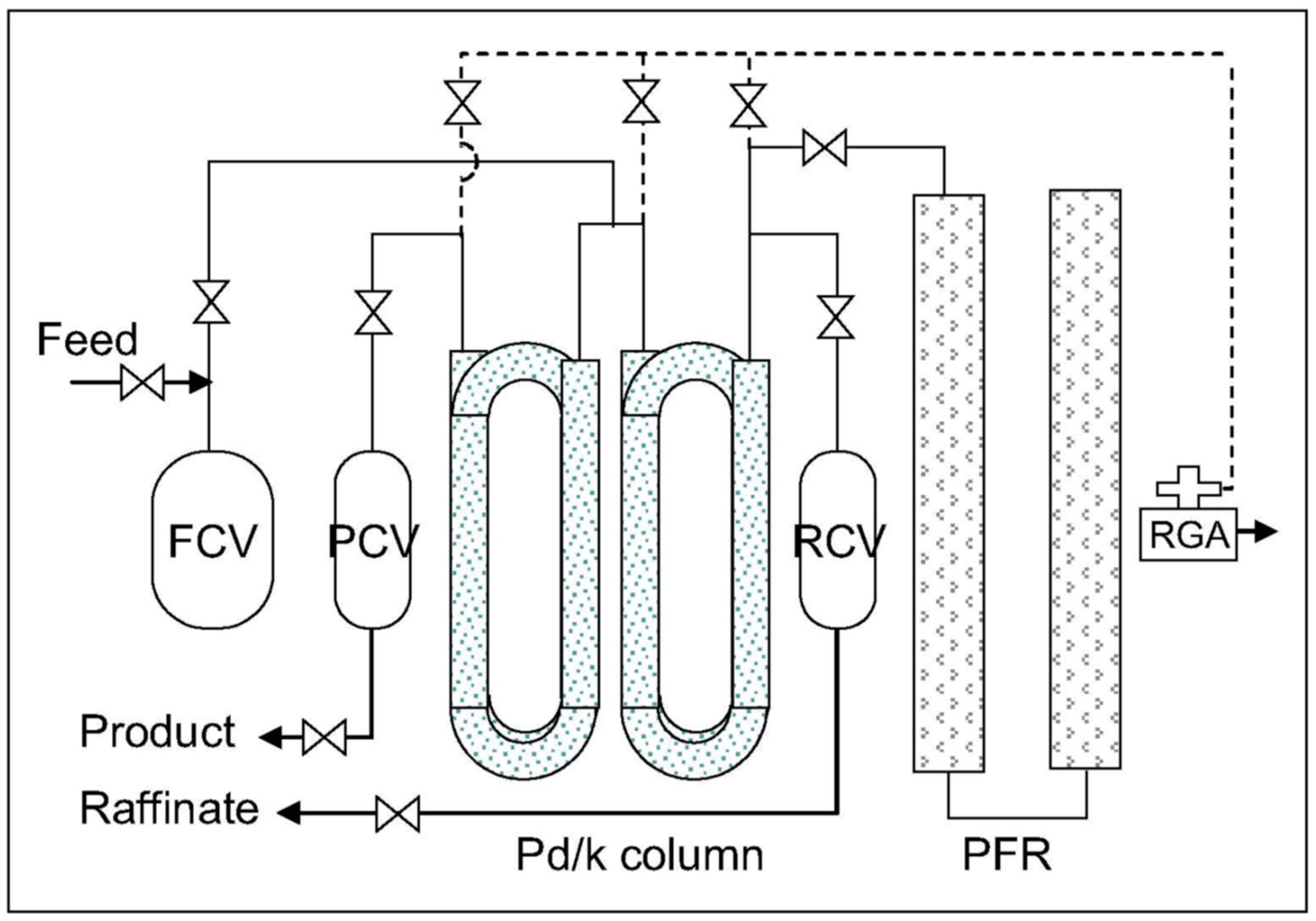
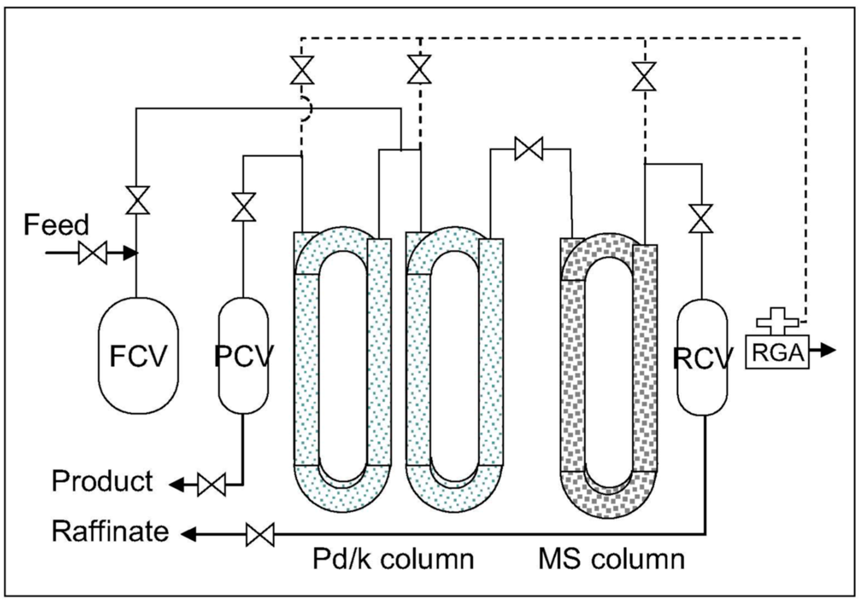
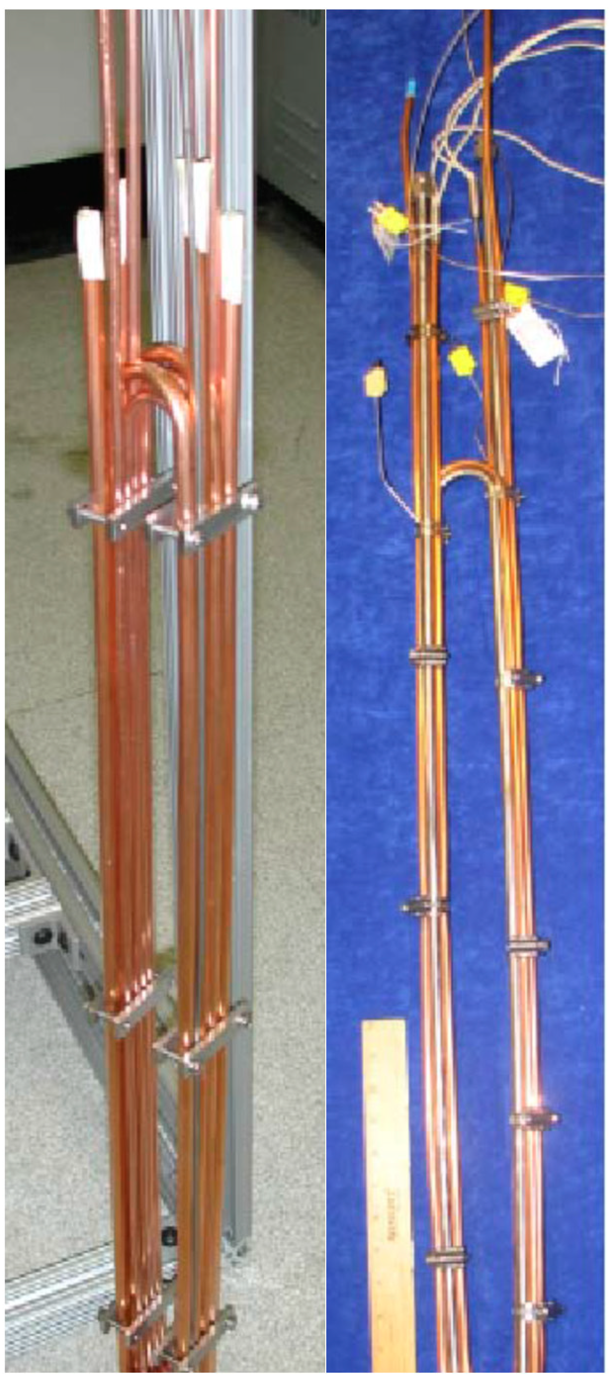
6.2. Thermal Cycling Absorption Process

In a preliminary work, a TCAP unit was studied in the frame of the hydrogen isotopic separation process under development at the ICSI (Institute for Cryogenic and Isotopic Technologies, Rm. Valcea, Romania) with the aim of recovering tritium from tritiated water [45]. This process uses a system based on the catalytic isotopic exchange between tritiated water and hydrogen/deuterium followed by a cryogenic distillation (CD) cascade consisting of four distillation columns [45]. In this work, the TCAP unit complements the CD cascade in order to reduce its tritium holdup. This TCAP unit adopts the basic (conventional) configuration, where palladium deposited on kieselguhr (Pd/k) packed column is coupled with a PFR (plug flow reverser). Such a solution produces a raffinate stream with a light-isotope purity level lower than the TCAP advanced configuration, which uses an active “inverse column”; for this reason, in the process studied at the ICSI, the raffinate stream had to be sent back and further treated in the CD cascade.
In order to produce both deuterium- (raffinate) and tritium (product)-enriched streams of the required purity levels without any need to recycle them into the CD cascade, in this work, the adoption of a TCAP system using an inverse column will therefore be considered for processing the stream leaving the bottom of the cryogenic distillation column of the water detritiation unit under study.
The following analysis moves from the results of the tests carried out by Heung et al. on TCAP systems in both the basic configuration (using a palladium packed column and a PFR), shown in Figure 5, and the new configuration, where an inverse column is used to replace the PFR, as shown in Figure 6 [35]. The PFR column (filled in with Pd/k) and the inverse column (filled in with molecular sieves) are shown in Figure 7. The tests, carried out with protium-deuterium mixtures, demonstrated that adopting the TCAP basic configuration purity levels of over 98% for both raffinate and product streams could be achieved operating with a feed flow rate of 1 STP L/cycle. However, in this operating mode the raffinate purity deteriorated at higher feed flow rate (3 STP L/cycle). When the PFR in this TCAP system was replaced by molecular sieves (inverse column), it was possible to achieve much better performance, namely, a raffinate purity 1% higher than that obtained by the basic configuration operated at feed flow rate of 4 STP L/cycle. Furthermore, as previously discussed, the other main advantages introduced by the new TCAP configuration consist of the reduction in the tritium inventory (to 1/2) and in the heat load (25%). The characteristics of the new TCAP configuration (Figure 7) considered in this analysis are:
-
the Pd/k column packed in copper tubing (0.95 cm diameter and 6.35 m long) operates from −70 to +145 °C at pressures from 1 to 5500 torr,
-
the inverse column (filled with 99 g of MS4A) in stainless steel tubing (0.95 cm diameter and 3.33 m long) operates at temperatures ranging from −190 to −90 °C and pressures ranging from 1 to 9000 torr,
-
heating via electrical resistance and cooling via liquid nitrogen.
With a feed flow rate of about 8 STP L/h (assessment based on a cycle duration of about 0.5 h), a raffinate and product purity of about 99% were obtained during an inherently safe, robust, and fault-proof operation [46].

6.3. Comparison GC/TCAP

In accordance with the experience of the JET in GC systems and of the SRNL in TCAP systems, in general, both of these processes comply with the purity levels required for the final purification of the cryo-distillation bottom stream proposed for the water detritiation unit studied in the TITANS project.
In fact, both systems have been extensively tested by demonstrating their safe operation while the technologies and the materials used have been validated in an industrially relevant environment corresponding to TRL levels of 6–7. Furthermore, both these systems could be downscaled for applications in small size units.
The GC system exhibits better separation performances since it can achieve purity levels of the deuterium- and tritium enriched-streams (99.96% and 99.70%, respectively) higher than those of the TCAP process, which, at its best, produces raffinate and product streams of purities around 99%. This difference could be significant when assessing the economic value of the streams produced or considering regulatory aspects for licensing the processes. Process temperatures are more favorable for GC (Tamb to 67 °C) than the TCAP (−70 to +145 °C and −190 to −90 °C for the Pd column and the inverse column, respectively).
These considerations are summarised in the Table 2.
In the end, although both systems (GC and the TCAP with an inverse column) comply with the requirements for application in small-size water detritiation units, the use of GC processes could be preferred in light of the above discussion.

7. Recent and Future Applications

The Savannah River National Laboratory has continually improved the TCAP’s ability to enrich tritium gas in a more cost-effective process that uses one-pass liquid nitrogen cooling and reduces the heat load and tritium risk. Miniature versions of TCAP systems that fit into a small glovebox extend the use of this process to several tritium applications [46].
A new process for the decontamination of tritiated water consisting of a hydrophilic column and a TCAP unit has been developed at the Savannah River National Laboratory, as shown in Figure 8 [47,48]. It works along three steps: (i) the tritium contained in the contaminated water is absorbed in the hydrophilic column, (ii) the absorbed tritium isotopes are exchanged by stripping the column with a gaseous hydrogen stream, and (iii) the tritium is separated by the hydrogen in the TCAP unit. Such a process does not require distillation units or electrolysers and, therefore, exhibits modest energy consumption while the presence of the TCAP unit can guarantee the achievement of high separation performances (99% T recovery and T concentrations in the H2 exhaust stream of less than 0.1 ppm).
An improved TCAP process adopting an oil bath heating and cooling system has been recently designed and tested with H2–D2 mixtures [49]. Pd/Al2O3 has been selected as a filling material for the separation columns, since it exhibits better thermal conductivity and greater Pd mass per unit volume than Pd–k. The temperature of the separation column ranges between −10 and +160 °C. By feeding with 50% H2—50% D2, the deuterium abundance in the product stream reaches 99.99% while good separation efficiency is maintained, even when feeding with streams with low deuterium concentrations. Although the separation of H–D could be, in general, easier than the separation of D–T [29], these results are of interest for future applications due to their milder thermal cycling temperature range.

8. Conclusions

This paper has analysed state-of-the-art water detritiation processes with a particular focus on hydrogen isotope separation systems based on displacement gas chromatography and the thermal cycling absorption process (improved with the use of an “inverse column”). These processes have been critically evaluated in order to establish their applicability for the final purification of the DT stream recovered at the bottom of the cry-distillation column of a water detritiation unit proposed for small scale applications.
In principle, both solutions (GC and the TCAP with an inverse column) exhibit safe and feasible operation and have achieved a good technological level by meeting the main design specifications required by applications for final separation in a water detritiation unit, namely, raffinate and product streams of purities > 99% and feed flow rates of 5 L/h. However, the use of GC has to be preferred since this system can operate with modest temperature cycling and exhibits a purity of the produced streams (close to 100%) higher than that of the TCAP system (≈99%).

Funding

This research was funded by the European Union under Grant Agreement n° 101059408 (TITANS project). Views and opinions expressed are, however, those of the author(s) only and do not necessarily reflect those of the European Union. Neither the European Union nor the granting authority can be held responsible for them.

Institutional Review Board Statement

Not applicable.

Informed Consent Statement

Not applicable.

Data Availability Statement

No new data were created.

Acknowledgments

The author wish to thank to Mirela Draghia from B&C Tech Solutions (Romania) for providing the characteristics of the process stream to be treated by the TCAP and GC systems.

Conflicts of Interest

The author declares no conflict of interest.

List of Acronyms

AGHSActive Gas Handling System at JET
CDCryogenic Distillation
CEACommissariat a l’Energie Atomique et aux Energies Alternatives
CECECombined Electrolysis and Catalytic Exchange
CFFTPCanadian Fusion Fuel Technology Project
FCFrontal chromatography
FDCFrontal displacement chromatography
DCDisplacement Chromatography
GCGas Chromatography
ICSIInstitute for Cryogenic and Isotopic Technologies at Rm. Valcea, Romania
JETJoint European Torus, Culham, UK
kKieselguhr, a diatomite chiefly composed of amorphous silica
LPCELiquid Phase Catalytic Exchange
MSMolecular Sieves
MS4AType 4A Molecular Sieves
PFRPlug Flow Reverser
SRNLSavannah River National Laboratory, USA
STPStandard Temperature and Pressure conditions (273.15 K and 100 kPa)
TCAPThermal Cycling Absorption Process
TLKTritium Laboratory of Karlsruhe, DE
TRLTechnological Readiness Level
VPCEVapour Phase Catalytic Exchange

References

  1. Chen, C.; Hou, J.; Li, J.; Chen, X.; Xiao, C.; Wang, Q.; Gong, Y.; Yue, L.; Zhao, L.; Ran, G.; et al. A water distillation detritiation facility and its performance test. Fusion Eng. Des. 2020, 153, 111460. [Google Scholar] [CrossRef]
  2. Iwai, Y.; Kubo, H.; Ohshima, Y.; Noguchi, H.; Taniuchi, J. Recent activities on water detritiation technology in JAEA. Fusion Eng. Des. 2016, 109-111, 1447–1451. [Google Scholar] [CrossRef]
  3. Kim, K.; Lee, M.; Paek, S.; Yim, S.; Ahn, D.; Chung, H. Operational analysis of a liquid phase catalytic exchange column for a detritiation of heavy water. Sep. Purif. Technol. 2007, 54, 410–414. [Google Scholar] [CrossRef]
  4. Zamfirache, M.; Bornea, A.; Balteanu, O.; Bucur, C.; Sofilca, N.; Stefanescu, I. Final status of water detritiation system (WDS) for Cernavoda Tritium removal facility (CTRF). Fusion Eng. Des. 2018, 136, 1038–1040. [Google Scholar] [CrossRef]
  5. Tamm, U.; Cristescu, I.-R.; Glugla, M.; Caldwell-Nichols, C. Investigation of simultaneous tritium and deuterium transfer in a catalytic isotope exchange column for water detritiation. Fusion Eng. Des. 2002, 61-62, 537–542. [Google Scholar] [CrossRef]
  6. Perevezentsev, A.N.; Bell, A.C. Development of a water detritiation facility for JET. Fusion Eng. Des. 2002, 61–62, 585–589. [Google Scholar] [CrossRef]
  7. Cristescu, I.R.; Dörr, L.; Glugla, M.; Hellriegel, G.; Michling, R.; Murdoch, D.; Schäfer, P.; Welte, S.; Wurster, W. Commissioning of water detritiation and cryogenic distillation systems at TLK in view of ITER design. Fusion Eng. Des. 2007, 82, 2126–2132. [Google Scholar] [CrossRef]
  8. Welte, S.; Cristescu, I.; Dittrich, H.; Lohr, N.; Melzer, C.; Michling, R.; Plusczyk, C.; Schaefer, P. Setup and commissioning of a combined water detritiation and isotope separation experiment at the Tritium Laboratory Karlsruhe. Fusion Eng. Des. 2013, 88, 2251–2254. [Google Scholar] [CrossRef]
  9. Miller, J.M.; Graham, W.; Celovsky, S.L.; Tremblay, J.; Everatt, A.E. Design and Operational Experience with a Pilot-Scale CECE Detritiation Process. Fusion Sci. Technol. 2002, 41, 1077–1081. [Google Scholar] [CrossRef]
  10. Hammerli, M.; Stevens, W.H.; Butler, J.P. Combined Electrolysis Catalytic Exchange (CECE) Process for Hydrogen Isotope Separation. ACS Symp. Ser. 1978, 68, 110–125. [Google Scholar] [CrossRef]
  11. Sicking, G. Isotope effects in metal-hydrogen systems. J. Less Common Met. 1984, 101, 169–190. [Google Scholar] [CrossRef]
  12. Wiswall, R.H.; Reilly, J.J. Inverse hydrogen isotope effects in some metal hydride systems. Inorg. Chem. 1972, 11, 1691–1696. [Google Scholar] [CrossRef]
  13. Pozio, A.; Tosti, S. Pd-Ag Electrical Resistivity in Hydrogen and Deuterium: Temperature Effect. Materials 2019, 12, 3551. [Google Scholar] [CrossRef] [PubMed]
  14. Liu, Y.; Wu, W.; Zhang, G.; Fang, M.; Jing, W.; Xiong, Y.; Xiong, R.; Tang, T. Study of separation factor and product extraction ratio in hydrogen isotope separation with displacement chromatography. Fusion Eng. Des. 2021, 165, 112246. [Google Scholar] [CrossRef]
  15. Deng, X.; Luo, D.; Qian, X. Development of separation materials containing palladium for hydrogen isotopes separation. J. Isot. 2010, 23, 53–58. [Google Scholar]
  16. Sazonov, A.B.; Magomedbekov, E.P. Estimate of the Efficiency of Hydrogen–Metal Hydride (Intermetallic Compound) Systems in the Separation of the Three-Isotope Mixtures H-D-T. At. Energy 2000, 89, 736–744. [Google Scholar] [CrossRef]
  17. Fukada, S.; Fuchinoue, K.; Nishikawa, M. Hydrogen isotope separation by displacement chromatography with palladium. J. Nucl. Sci. Technol. 1995, 32, 556–564. [Google Scholar] [CrossRef]
  18. Deng, X.; Luo, D.; Qin, C.; Qian, X.; Yang, W. Hydrogen isotopes separation using frontal displacement chromatography with Pd–Al2O3 packed column. Int. J. Hydrogen Energy 2012, 37, 10774–10778. [Google Scholar] [CrossRef]
  19. Ducret, D.; Ballanger, A.; Steimetz, J.; Laquerbe, C.; Baudouin, O.; Peyrigain, P.S. Hydrogen isotopes separation by thermal cycling absorption process. Fusion Eng. Des. 2001, 58-59, 417–421. [Google Scholar] [CrossRef]
  20. Heung, L.K.; Sessions, H.T.; Poore, A.S.; Jacobs, W.D.; Williams, C.S. Next-generation TCAP hydrogen isotope separation process. Fusion Sci. Technol. 2008, 54, 399–402. [Google Scholar] [CrossRef]
  21. Available online: https://titans-project.eu/ (accessed on 12 July 2023).
  22. Tosti, S.; Pozio, A. Membrane Processes for the Nuclear Fusion Fuel Cycle. Membranes 2018, 8, 96. [Google Scholar] [CrossRef] [PubMed]
  23. Brooks, K.; Sevigny, G. (Eds.) Love, Review and Evaluation of Water Detritiation Technologies for Watts Bar Primary Cooling Water, Pacific Northwest National Laboratory, 10 May 2017, EMSL Auditorium, PNNL, PNNL-SA-125901. Available online: https://www.google.com/url?sa=t&rct=j&q=&esrc=s&source=web&cd=&ved=2ahUKEwij0M__74v_AhUS7aQKHaRSB4QQFnoECBAQAQ&url=https%3A%2F%2Fwww.energy.gov%2Fsites%2Fprod%2Ffiles%2F2017%2F06%2Ff34%2FMay%252010%2520-%2520Brooks-Review%2520of%2520Water%2520Detritiation%2520Technologies.pdf (accessed on 12 July 2023).
  24. Kalyanam, K.; Sood, S. A Comparison of Process Characteristics for the Recovery of Tritium from Heavy Water and Light Water Systems. Fusion Technol. 1988, 14, 524–528. [Google Scholar] [CrossRef]
  25. Libby, W.F. Vibrational Frequencies of the Isotopic Water Molecules; Equilibria with the Isotopic Hydrogens. J. Chem. Phys. 1943, 11, 101–109. [Google Scholar] [CrossRef]
  26. Paek, S.; Ahn, D.-H.; Choi, H.-J.; Kim, K.-R.; Lee, M.; Yim, S.-P.; Chung, H.; Song, K.-M.; Sohn, S.H. The performance of a trickle-bed reactor packed with a Pt/SDBC catalyst mixture for the CECE process. Fusion Eng. Des. 2007, 82, 2252–2258. [Google Scholar] [CrossRef]
  27. Park, D.; Urm, J.J.; Lee, J.-U.; Chang, M.H.; Lee, J.M. Dynamic optimization of cryogenic distillation operation for hydrogen isotope separation in fusion power plant. Int. J. Hydrogen Energy 2021, 46, 24135–24148. [Google Scholar] [CrossRef]
  28. Glugla, M.; Murdoch, D.; Antipenkov, A.; Beloglazov, S.; Cristescu, I.-R.; Day, C.; Laesser, R.; Mack, A. ITER fuel cycle R&D: Consequences for the design. Fusion Eng. Des. 2006, 81, 733–744. [Google Scholar] [CrossRef]
  29. Liu, Y.; Wu, W.; Xiong, Y.; Zhang, G.; Wei, Y.; Fang, M.; Tang, T. Protium removal from deuterium-tritium mixture with displacement chromatography method: Experiments and simulations. Int. J. Hydrogen Energy 2019, 44, 3824–3833. [Google Scholar] [CrossRef]
  30. Shugard, A.D.; Buffleben, G.M.; Johnson, T.A.; Robinson, D.B. Isotope exchange between gaseous hydrogen and uranium hydride powder. J. Nucl. Mater. 2014, 447, 304–313. [Google Scholar] [CrossRef]
  31. Yawny, A.; Friedlmeier, G.; Bolcich, J. Hydrides for hydrogen-deuterium separation. Int. J. Hydrogen Energy 1989, 14, 587–597. [Google Scholar] [CrossRef]
  32. Watanabe, K.; Matsuyama, M.; Kobayashi, T.; Taguchi, S. Gas chromatographic separation of H2-D2 mixtures by Pd-Pt alloy near room temperature. J. Alloys Compd. 1997, 257, 278–284. [Google Scholar] [CrossRef]
  33. Watanabe, K.; Matsuyama, M.; Kobayashi, T.; Shu, W.M. Hydrogen isotope separation by gas chromatography using Pd–Pt alloy. Fusion Eng. Des. 1998, 39-40, 1001–1008. [Google Scholar] [CrossRef]
  34. Maeland, A.; Flanagan, T.B. Lattice Constants and Thermodynamic Parameters of the Hydrogen-Platinum-Palladium and Deuterium-Platinum-Palladium Systems. J. Phys. Chem. 1964, 68, 1419–1426. [Google Scholar] [CrossRef]
  35. Heung, L.K.; Sessions, H.T.; Xiao, X. TCAP Hydrogen Isotope Separation Using Palladium and Inverse Columns. Fusion Sci. Technol. 2011, 60, 1331–1334. [Google Scholar] [CrossRef]
  36. Qian, X.J.; Luo, D.L.; Qin, C.; Huang, G.Q.; Yang, W. FTP/P 106 Gas Chromatography Separation of H 2-D 2-Ar Using Pd/K. 2010. Available online: https://www-pub.iaea.org/mtcd/meetings/PDFplus/2010/cn180/cn180_papers/ftp_p1-06.pdf (accessed on 12 July 2023).
  37. Neffe, G.; Besserer, U.; Dehne, J.; Hutter, E.; Kissel, H.; Penzhorn, R.; Wendel, J.; Brunnader, H. Routine operation of the gas chromatographic isotope separation system of the Tritium Laboratory Karlsruhe. Fusion Eng. Des. 1998, 39-40, 987–993. [Google Scholar] [CrossRef]
  38. Cheh, C.H. Large Scale Gas Chromatographic Demonstration System for Hydrogen Isotope Separation. Fusion Technol. 1988, 14, 567–573. [Google Scholar] [CrossRef]
  39. Lässer, R.; Bell, A.C.; Bainbridge, N.; Brennan, D.; Dörr, L.; Hemmerich, J.L.; Knipe, S.; Stagg, R. The preparative gas chromatographic system for the JET Active Gas Handling System—Tritium commissioning and use during and after DTE1. Fusion Eng. Des. 1999, 47, 301–319. [Google Scholar] [CrossRef]
  40. Shmayda, W.T.; Wittman, M.D.; Earley, R.F.; Reid, J.L.; Redden, N.P. The Laboratory for Laser Energetics’ Hydrogen Isotope Separation System. Fusion Eng. Des. 2016, 109-111, 128–134. [Google Scholar] [CrossRef]
  41. Klein, J.E. (Ed.) Heung, L.K.; Howard, D.W.; Lee, M.W.; Motyka, T.; Poore, A.S.; Scogin, J.H. Conceptual Design for Consolidation TCAP, Report WSRC.TR-97-00340, 24 October 1997, Savannah River Technology Center. Available online: https://www.osti.gov/servlets/purl/4820 (accessed on 12 July 2023).
  42. Xiao, X.S.; Heung, L.K.; Sessions, H.T.; Redd, S. Advances in Hydrogen Isotope Separation Using Thermal Cycling Absorption Process (TCAP). Available online: https://www.google.com/url?sa=t&rct=j&q=&esrc=s&source=web&cd=&ved=2ahUKEwiC-rfq0eT5AhVQXfEDHajvAp4QFnoECAUQAQ&url=https%3A%2F%2Fenergy.gov%2Fsites%2Fprod%2Ffiles%2F2015%2F08%2Ff26%2FSRNL-STI-2013-00230%2520Rev1_Advances%2520in%2520TCAP%2520(Xiao).pdf&usg=AOvVaw1C3s5IDVNlQoqv5FITED4a (accessed on 12 July 2023).
  43. Clark, E.A. Materials Performance in Prototype Thermal Cycling Absorption Process (TCAP) Columns (U); Report WSRC.TR-92-552-552; Savannah River Technology Center: Aiken, SC, USA. [CrossRef]
  44. Zhou, J.; Zhang, X.; Hao, S.; Huang, W. Dynamic simulation of Thermal Cycling Absorption Process with twin columns for hydrogen isotopes separation. Int. J. Hydrogen Energy 2014, 39, 13873–13879. [Google Scholar] [CrossRef]
  45. Ana, G.; Niculescu, A.; Bornea, A.; Zamfirache, M.; Draghia, M. TCAP Hydrogen Isotope Separation Process Under Development at ICSI Rm. Valcea. IEEE Trans. Plasma Sci. 2018, 46, 2668–2671. [Google Scholar] [CrossRef]
  46. Xiao, X.; Randall, B.; Sessions, H.T.; Allgood, R.; Babineau, D. Thermal Cycling Absorption Process Overview, Presentation of Savannah River National Laboratory. Available online: https://www.energy.gov/sites/prod/files/2019/06/f63/Thermal-Cycling-Absorption-Process-Overview.pdf (accessed on 12 July 2023).
  47. Decontamination of Tritiated Water, TechBriefs SRNL 14.09.2020, SRNL-MS-2020-00101. Available online: https://srnl.doe.gov/tech_transfer/tech_briefs/SRNL_TechBriefs_decontamination-of-tritiated-water.pdf (accessed on 12 July 2023).
  48. Xiao, X. Decontamination of Tritiated Water. U.S. Patent 10,381,121 B2, 13 August 2019. Available online: https://patents.google.com/patent/US10381121B2/en?oq=48.Xiao%2c+X.+Decontamination+of+Tritiated+Water%2c+Patent+No.+US+10%2c381%2c121+B2+(13+August+2019)file:///D:/ (accessed on 28 August 2023).
  49. Deng, L.; Chen, C.; Huang, G.; Shi, Y.; Yao, Y.; Hu, J.; Chen, K.; An, Y.; Song, J. The oil bath thermal cycling absorption process design and separation process research. Int. J. Hydrogen Energy 2023, 48, 22132–22140. [Google Scholar] [CrossRef]
Figure 1. Corrugated structured packing of distillation columns [1]. Reprinted from Fusion Engineerign and Design, Vol 153, Chen, C.; Hou, J.; Li, J.; Chen, X.; Xiao, C.; Wang, Q.; Gong, Y.; Yue, L.; Zhao, L.; Ran, G.; et al. A water distillation detritiation facility and its performance test, Pages No.111460, Copyright (2020), with permission from Elsevier.
Hydrogen 04 00044 g001
Figure 2. Water distillation detritiation facility [1]. Reprinted from Fusion Engineerign and Design, Vol 153, Chen, C.; Hou, J.; Li, J.; Chen, X.; Xiao, C.; Wang, Q.; Gong, Y.; Yue, L.; Zhao, L.; Ran, G.; et al. A water distillation detritiation facility and its performance test, Pages No.111460, Copyright (2020), with permission from Elsevier.
Hydrogen 04 00044 g002
Figure 3. CECE process for tritiated water treatment [26]. Reprinted from Fusion Engineerign and Design, Vol 82, Paek, S.; Ahn, D.-H.; Choi, H.-J.; Kim, K.-R.; Lee, M.; Yim, S.-P.; Chung, H.; Song, K.-M.; Sohn, S.H. The performance of a trickle-bed reactor packed with a Pt/SDBC catalyst mixture for the CECE process, Pages No. 2252–2258, Copyright (2007), with permission from Elsevier.
Hydrogen 04 00044 g003
Figure 4. Water detritiation system proposed for ITER (2006): combination of the CECE process with cryogenic distillation [28]. Reprinted from Fusion Engineerign and Design, Vol 81, Glugla, M.; Murdoch, D.; Antipenkov, A.; Beloglazov, S.; Cristescu, I.-R.; Day, C.; Laesser, R.; Mack, A. ITER fuel cycle R&D: Consequences for the design, Pages No. 2252–2258, Copyright (2006), with permission from Elsevier.
Hydrogen 04 00044 g004
Figure 5. Schematic of the conventional TCAP [35]—TCAP Hydrogen Isotope Separation Using Palladium and Inverse Columns, L. K. Heung, H. T. Sessions & X. Xiao, (2011) Fusion Science and Technology, copyright © 2011 American Nuclear Society, reprinted by permission of Taylor & Francis Ltd., http://www.tandfonline.com on behalf of 2011 American Nuclear Society.
Hydrogen 04 00044 g005
Figure 6. The TCAP in the Pd/k-MS configuration [35]—TCAP Hydrogen Isotope Separation Using Palladium and Inverse Columns, L. K. Heung, H. T. Sessions & X. Xiao, (2011) Fusion Science and Technology, copyright © 2011 American Nuclear Society, reprinted by permission of Taylor & Francis Ltd., http://www.tandfonline.com on behalf of 2011 American Nuclear Society.
Hydrogen 04 00044 g006
Figure 7. Pd/k (left picture) and MS (right picture) columns of the TCAP systems developed at SRNL [35]—TCAP Hydrogen Isotope Separation Using Palladium and Inverse Columns, L. K. Heung, H. T. Sessions & X. Xiao, (2011) Fusion Science and Technology, copyright © 2011 American Nuclear Society, reprinted by permission of Taylor & Francis Ltd., http://www.tandfonline.com on behalf of 2011 American Nuclear Society.
Hydrogen 04 00044 g007
Figure 8. A water detritiation process developed at the SRNL consisting of a hydrophilic column and a TCAP unit. Reprinted from Ref. [47] with permission from the SRNL (Savannah River National Laboratory, USA).
Hydrogen 04 00044 g008
Table 1. Separation factors of the VPCE and LPCE processes [24].
VPCE (473 K)LPCE (298 K)
D/T1.221.67
H/T2.137.14
Table 2. Comparison GC/TCAP.
Streams’ PurityProcessing TTRLSafety
GC>99%Tamb to 67 °C6–7inherent safety validated in experiments
TCAP *≈99%−70 to +145 °C
−190 to −90 °C
6–7inherent safety validated in experiments
* with inverse columns.
Disclaimer/Publisher’s Note: The statements, opinions and data contained in all publications are solely those of the individual author(s) and contributor(s) and not of MDPI and/or the editor(s). MDPI and/or the editor(s) disclaim responsibility for any injury to people or property resulting from any ideas, methods, instructions or products referred to in the content.

