Article

Techno-Economic Analysis of a Process to Convert Methane to Olefins, Featuring a Combined Reformer via the Methanol Intermediate Product

by
Abdulaziz Alturki
1,2
1
Department of Chemical and Materials Engineering, Faculty of Engineering—Rabigh Branch, King Abdulaziz University, Jeddah 21589, Saudi Arabia
2
Department of Chemical and Biomolecular Engineering, University of California Los Angeles, Los Angeles, CA 90095, USA
Hydrogen 2022, 3(1), 1-27; https://doi.org/10.3390/hydrogen3010001
Submission received: 11 November 2021 / Revised: 9 December 2021 / Accepted: 25 December 2021 / Published: 30 December 2021
(This article belongs to the Special Issue Feature Papers in Hydrogen)

Abstract

:
The substantial growth in shale-derived natural gas production in the US has caused significant changes in the chemical and petrochemical markets. Ethylene production of ethane and naphtha via steam cracking is one of the most energy- and emission-intensive activities in chemical manufacturing. High operating temperatures, high reaction endothermicity, and complex separation create high energy demands as well as considerable CO2 emissions. In this study, a demonstration of a transformational methane-to-ethylene process that offers lower emissions using energy optimization and a CO2 minimum-emission approach is presented. The comparisons of different reforming processes suggest that the dry reforming of methane has a negative carbon footprint at low syngas ratios of 1 and below, and that additional carbon emissions can be reduced using integrated heating and cooling utilities, resulting in a 99.24 percent decrease in CO2. A process design implemented to convert methane into value-added chemicals with minimum CO2 emissions is developed.

1. Introduction

Despite significant efforts to develop renewable energy, fossil fuels continue to dominate global energy providers as a source of 80.7% of the world’s energy, totaling 601.5 quadrillion BTU in 2020 [1]. The shale gas revolution has enabled the tapping of natural gas as an abundant, versatile, and economical alternative feedstock to conventional fuels. Natural gas (shale gas) is predominantly composed of methane and is expected to outlast oil by a significant margin. Driven by advancements in hydraulic fracturing and horizontal drilling technologies, US natural gas production increased by 91% between 2005 and 2020. Production has shifted from traditional regions, such as the Gulf of Mexico, to locations far away from the areas of consumption. This has resulted in increases in the cost of transportation. Therefore, there is a need to convert natural gas into more economically desirable products, such as fuels for transportation as a liquid and those with higher energy density [2]. Currently, after shale gas is purified and fractionated, the natural gas liquids (NGLs) that are produced have a considerably higher market value than methane. The current exportation of natural gas to markets is dominated by pipelines and NGLs. These light NGLs, such as ethane, propane, and butane, are used as a feedstock to produce olefins, while the residual heavier fractions (C5+ hydrocarbon) are used as gasoline stock. The use of methane gas in the production of olefins and other chemicals has the high potential to be a “game-changer” in the chemical industry. A number of researchers have attempted to develop a cost-effective methane-to-chemicals integrated process through syngas production [3,4,5]. Once syngas is produced, it can be transformed into numerous intermediates and products. Examples of chemicals that can be transformed into products include methanol [6,7], ethylene [8], propylene [9], benzene [10], and liquid transportation fuels. [11] Olefins are a vital chemical value chain as they are used to produce value-added chemicals, such as plastics, synthetic rubber, and adhesive materials [12]. The importance of olefins results from the double bond in their molecular structure; when this bond is broken down, the molecules can easily form two new single bonds, giving a range of different reactions.
Methane dominates NGLs in shale gas, comprising 75–90% of the total gas production. However, methane has a high C–H bond strength (434 kJ/mol) with considerable ionization energy, which makes the bond challenging to break [13,14]. Currently, 70% of the methane converted into chemicals is used for ammonia production; 20% is used for methanol production, and the remainder is used in a variety of chemicals, such as hydrogen cyanide, acetylene, and oxo chemicals, among others. Methane can be converted into higher hydrocarbons (e.g., ethylene and aromatics) via indirect or direct routes. In the indirect routes, methane is converted via the reforming process into syngas (a mixture of CO and H2), which can be further used as an intermediate to produce methanol and then olefins via a multi-step catalytic reaction, in a strategy that is called “methanol to olefins” (MTO) [15,16,17]. The three main routes for generating syngas from natural gas are steam methane reforming (SMR), partial oxidation (POX), and the dry reforming of methane (DRM). Each of these routes uses a different oxidizing agent (i.e., steam, oxygen, or carbon dioxide) and operating conditions to produce different syngas (H2/CO) ratios [18].
SMR refers to the catalytic conversion of natural gas in the presence of steam [19]. Steam reforming has become the most common commercial technology used to produce syngas and hydrogen. The partial oxidation of natural gas is an exothermic catalytic or noncatalytic reaction that involves oxygen. SMR is an endothermic reaction that involves the reaction of natural gas and carbon dioxide to produce syngas in the presence of a catalyst [20,21]. Tri-reforming is a synergetic combination of DRM, POX, and SMR in a single reactor [22]. In addition to the merits of energy integration, the tri-reforming process represents a new method for the conversion and utilization of CO2 in flue gas without CO2 separation. Rather than being treated as waste or stored underground, CO2 can be used as a chemical feedstock for upscaling synthesis that does not rely on a petrochemical source. Carbon capture and utilization rely on post-computation CCS technologies to provide value-added products, offset the cost of operation, and make the process profitable. It is even more viable to use flue gas CO2 than purified CO2. The typical furnace outlet of flue gases is usually around 1200 °C. The injection of CO2 allows the H2/CO ratio to be controlled. A synergistic combination of the reforming of methane, such as DRM + SMR, DRM + POX, and DRM + SMR + POX has been recommended to tackle the limitations of each process individually [22,23]. The direct routes from one-step methane involve the conversion via oxidative coupling of methane (OCM) to higher hydrocarbons. In OCM, methane is directly converted to ethylene in a catalytic reactor. The OCM still has minimal economic potential compared to the well-established cracking process [24]. The major limitation of the OCM process is its low C2 hydrocarbon yield (ethane and ethylene, <20 mol %) and selectivity (<50%), and a large amount of unreacted gas and byproducts. These disadvantages result in high product separation costs and a high carbon footprint.
In addition to the recent discoveries of unconventional shale gas resources, which have increased the global supply of natural gas significantly, cost reduction in renewable energies is creating opportunities for energy transitions, with wind and solar photovoltaics (PV) predicted to provide more than half of electricity generation in the US by 2040 [25]. In addition, the US is expected to increase its global market share of ethylene from 20% in 2017 to 22% by 2025. The US has the advantage of low-cost ethane, due to an abundant natural gas supply as a result of the shale-gas revolution [25].
Recent publications have considered shale gas as feedstock to produce syngas [26], methanol [7], and light olefins [8,9]. Ehlinger et al. performed a techno-economic analysis for shale-gas conversion to methanol and concluded that this process is profitable in comparison to the prices of methanol and natural gas [6]. Niziolek et al. carried out a framework that produced aromatics (benzene, toluene, and xylene) from natural gas, via methanol as an intermediate product [27]. He and You developed three processes that integrate shale-gas processing facilities, using ethane-steam-cracking to increase the overall profitability of the process [28]. The same authors later combined the conversion of shale gas and the dehydration of bioethanol to improve the economics of ethylene production [14]. Salkuyeh and Adams proposed a process to both produce ethylene and electricity from shale gas with minimum CO2 emissions through the methane oxidative coupling process.
Light olefins are produced commercially by three different methods: a fired tubular heater using ethane, propane, and naphtha; auto-thermal cracking of crude oil; and synthesis from hydrogen and carbon monoxide. Ethane and propane are separated from natural gas via an energy-intensive cryogenic process, before being converted into light olefins (ethylene and propylene). Our goal is to determine whether producing light olefins directly from methane—or natural gas that is composed mainly of methane—is more cost-effective than extracting and separating ethane and propane from natural gas and converting them into light olefins.
This work considers various gas-reforming technologies for methanol, such as partial oxidation (POX), SMR, autothermal reforming (ATR), and combined reforming (CR). Additionally, single-step natural gas conversions into olefins and higher hydrocarbons are considered. We develop a flexible approach to evaluate various technologies systematically, determine the appropriate process for converting methane into ethylene, and perform energy and economic analyses. For each particular reformer, specified inputs and operating conditions are analyzed to determine the syngas composition. The appropriate reformer is defined as the one that is able to achieve the objectives as determined by the inputs and operating conditions. We evaluate the profitability of OCM and MTO processes for the production of ethylene compared to cracking ethane. The analyses are derived using an Aspen Plus simulator.

Problem Statement

  • Shale gas that consists primarily of methane is an abundant, low-cost, carbon-containing feedstock that is widely available globally. An economically viable route for producing useful chemicals from methane is via the synthesis of gas, followed by various processes to manufacture the required chemicals. In a large-scale industrial plant, the production of syngas represents a sizable part of the total operating costs. Therefore, it is essential to develop efficient methods and cost-effective techniques to convert methane into syngas and to integrate them with downstream chemical processes to produce methanol and ethylene.
  • Steam cracking is a well-established industrial process for the production of ethylene. Despite optimization efforts, the procedure still uses a large amount of energy and is a carbon-intensive process.
  • Given the considerable progress in these research areas and a significant increase in methane, significant opportunities in the advancement and eventual implementation of intensified ethylene production technologies are available.
Given the methane stream, it is desirable to develop, simulate, and integrate an olefin production plant with three different technologies for the syngas plant and then perform a techno-economic analysis to answer the following questions: (1) What does a process flowsheet look like? (2) What are the opportunities for heat integration for each form of syngas technology? (3) Which process route from methane to ethylene is more energy-optimal?

2. Approach and Modeling

Design Basis and Assumptions

The process herein was developed using Aspen Plus and equipment costs were estimated using the exponential scaling expression, based on the size of the equipment and cost data from the Aspen Process Economic Analyzer. Aspen Energy was used to extract hot and cold stream data and apply thermal pinch analysis. Modern-day catalysts are able to achieve compositions close to the equilibrium for reforming systems [22,29]. Equilibrium modeling is essential to identify the system’s response to changing variables, such as temperature and pressure. The Gibbs free energy minimization method has been applied widely to calculate the equilibrium composition of a system [30]. The reformer reactors of the methane to ethylene flowsheet use substantial amounts of energy. Thus, particular attention was given to modeling different reforming technologies. In most syngas processing routes, the reformer section is operated at a high temperature (800–1200 °C) [31,32]. The reformer is a complex section and depends on the downstream application of technology. The world’s largest gas-to-liquid (GTL) plants, ORYX GTL by Sasol-Chevron and Pearl and GTL by Shell, use auto thermal reforming (ATR) and partial oxidation (POX), respectively [33]. Methanol synthesis can also use different reforming approaches, such as SMR, POX, and DRM. Various studies have indicated that reformer catalysts are capable of achieving compositions close to equilibrium [22,29,32]. Therefore, equilibrium models are useful in providing an estimate for reformer conversion.
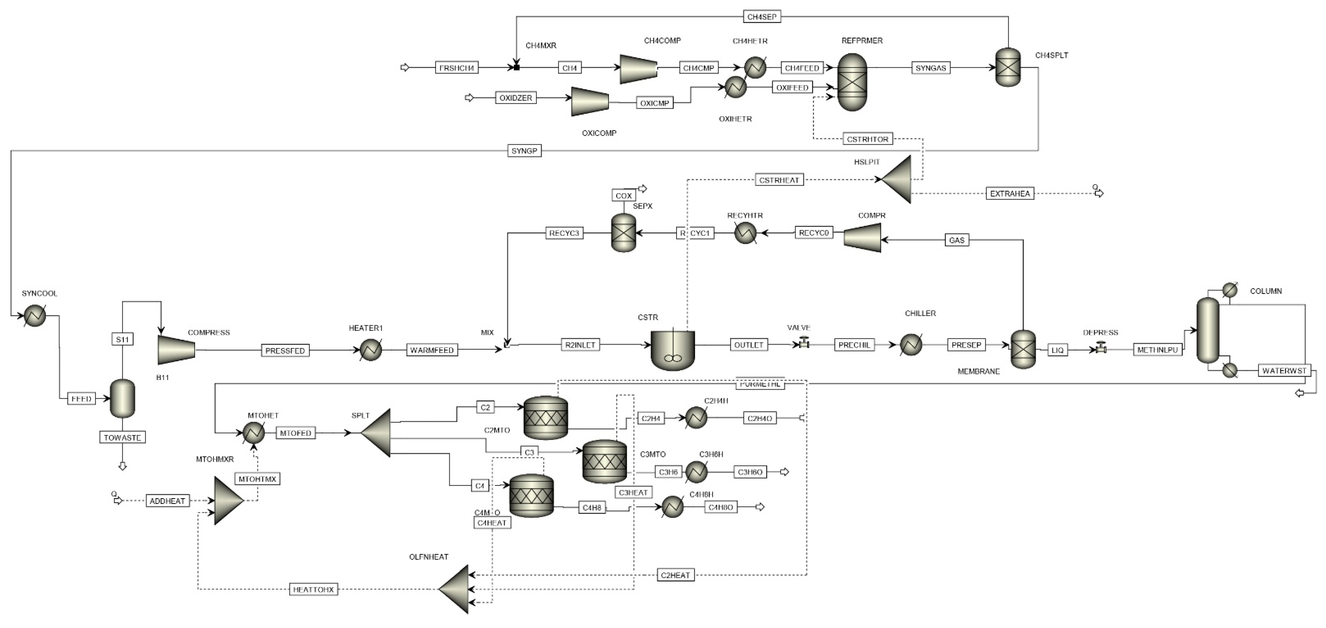
The Peng–Robinson equation of state was used to simulate the SMR, POX, DRM, and water-gas shift (WGS) sections of the flowsheet, while for the methanol and ethylene synthesis sections, the UNIFAC VLE liquid activity model and Peng–Robinson equation were used. The input streams of the flowsheet consisted of methane, oxygen, and water (as needed) at 100 kPa, 298 K, and the output streams consisted of ethylene, hydrogen, and water in the same condition. A Gibbs free energy minimization reactor was used to represent the SMR, POX, DRM, WGS, and methanol synthesis, while the OCM reactor and ethylene synthesis reactor were modeled using a conversion reactor. The MTO reactor was modeled using the yield reactor. A simplified block flow diagram of the overall process with the different configurations for methane to ethylene routes is illustrated in Figure 1. The sequence of the process described was obtained via knowledge taken from the literature. Operating conditions were adjusted based on guidelines in the literature that described steps to simulate these parameters.
The following assumptions were made for the development of the process flow sheet:
  • All of the inputs to the flow sheet consist of pure components;
  • Pressure drop is neglected in the exchange devices (heaters and coolers).

3. Process Description

The proposed process is shown in Figure 1 and comprises the following sections: (1) methane conversion; (2) synthesis gas cleaning; (3) methanol synthesis; and (4) methanol conversion and olefin production. This is a gas pretreatment process, whereby raw shale gas is purified in a gas-sweetening unit. The process of methane separation from natural gas is not included in the analysis of this study.

3.1. Catalytic Conversion

In the following sections, we consider ethane cracking as a reference and the direct and oxidative conversion of methane to olefins, as well as using reforming to produce methanol as an intermediate product for the synthesis of olefins.

3.1.1. Reforming

Syngas production consists of three primary unit operations: the saturator, performer, and reformer. The ratio of steam or CO2, in addition to reformers, depends on the type of reformer used. In this study, CO2 is assumed to be obtained from SMR, methanol synthesis, and OCM processes. Different reforming processes are considered here and are described below.

Steam Methane Reforming (SMR)

Methane is converted into synthesis gas (syngas) via an SMR process. The SMR unit operates at a temperature of 1073–1173 K and a pressure of 30 bar. A nickel-based catalyst is used in the reactor tubes, where the steam methane reforming (Equation (1)) and WGS (Equation (2)) reactions reach equilibrium. Since the reforming reaction is endothermic, an external supply of heat is required.
CH 4 + H 2 O CO + 3 H 2 ,   Δ H 298 K 0 = 206.1   kJ / mol
C O + H 2 O CO 2 + H 2 ,   Δ H 298 K 0 = 41   kJ / mol

Partial Oxidation (POX)

In this process, syngas is produced from heavy hydrocarbons. Oxygen is provided from an air separation unit [2]. The oxidation reaction in the POX is as follows:
CH 4 + 0.5 O 2 CO + 2 H 2 ,   Δ H 298 K 0 = 36   kJ / mol
CH 4 + 1.5 O 2 CO + 2 H 2 O ,   Δ H 298 K 0 = 519   kJ / mol
CH 4 + 2 O 2 CO 2 + 2 H 2 O ,   Δ H 298 K 0 = 802   kJ / mol
The reformer feed is heated to 650 °C before it enters the POX reactor. Oxygen is fed into the reactor at 200 °C to maintain the molar ratio at O2/CH4 = 0.65 [34]. The converted gas leaves the POX reactor at between 1200 and 1500 °C [23]. Partial oxidation leads to a syngas ratio (H2:CO) of 1.8. This ratio can be adjusted to 2 by a WGS reaction. To obtain the desired H2/CO ratio, the converted gas from POX is cooled to 370 °C and fed into the water gas shift (WGS) reactor, which operates at 250–400 °C and 30 bar (Equation (2)). In this process, syngas is cooled and water is separated with a flash unit at 45 °C and 30 bar.

Autothermal Reforming (ATR)

Autothermal reforming is an alternative process to SMR. This process combines the technologies of SMR and POX, such that oxygen and steam react with methane in an endothermic reaction to produce syngas. The partial combustion of methane is carried out to offset the heat required by the endothermic reforming reaction. The steam-to-carbon ratio for the reactor inlet is constrained to be larger than 0.5 ATR and is carried out through methane oxidation by oxygen and water, as shown in the reactions described in Equations (1), (3) and (4) [34,35]. The combination of SMR and POX reactions yields a unique approach in which partial combustion of the hydrocarbon feed is balanced by the endothermic requirements of the steam reforming reactions.
The stream form performer is heated to a temperature of 650 °C before the stream is fed into the autothermal reformer (ATR). Oxygen is fed into the reactor at 200 °C, and the molar ratio is kept at O2/CH4 = 0.59 [34]. Superheated steam is also added to the stream to ensure that the desired molar ratio of H2/CO is achieved in the produced syngas. The temperature of the converted gas at the reactor outlet stream is equal to 1050 °C.

Dry Reforming of Methane (DRM)

DRM is a well-defined technology that is of both scientific and industrial importance. This process was first studied by Fisher and Tropsch in 1928, using catalysts such as Ni and Co, and, since then, has been investigated in a large number of studies [2]. However, this process has not been industrialized yet [36]. DRM utilizes CO2 to convert methane into a syngas mixture (H2 and CO). This process is challenged by high energy requirements (DRM = 247 kJ/mol while SMR = 206 kJ/mol), susceptibility to coke formation, and low-quality syngas (syngas ratio, H2/CO~1). However, this process provides an attractive route for the cost-effective sequestration of CO2 to make value-added chemicals and fuels. Compared to SMR and POX, DRM has the advantage of using CO2 as an oxidant, which gains credit in the CO2 balance in the process.
CH 4 + CO 2 2 CO + 2 H 2 ,   Δ H 298 K 0 = 247   kJ / mol

3.1.2. Methanol Synthesis

Syngas, produced by all methods, is cooled to 40 °C to separate the excess water. The dry gas is sent to the carbon dioxide extraction unit to remove CO2 via methyl diethanolamine (MDEA). The purified gas then leaves the absorber and goes to the hydrogen extraction unit, to maintain the syngas molar ratio of H2/CO at the desired value of ~2.2. The resulting gas is fed into the methanol reactor. The chemical reaction for methanol synthesis from syngas is as follows:
CO 2 + 3 H 2 CH 3 OH + H 2 O ,   Δ H 298 K 0 = 49.43   kJ / mol
CO + 2 H 2 CH 3 OH ,   Δ H 298 K 0 = 90.55   kJ / mol
The reaction of the reverse water–gas shift (RWGS) is as follows:
H 2 + CO 2 CO + H 2 O ,   Δ H 298 K 0 = 41   kJ / mol
The routes were initially developed by Badische Anilin- und Soda-Fabrik (BASF), operating at high pressure (250–350 bar) at a temperature of 320–450 °C, over a ZnO/Cr2O3 catalyst. In 1960, ICI (now called Syntex) developed a low-pressure process that operates at 35–55 bar and 200–300 °C, over Cu/ZnO/Al2O3 catalysts [7,37,38]. Methanol reaction synthesis usually occurs as a combination of two reactions in the syngas mixture: the first reaction involves carbon dioxide and hydrogen (Equation (6)), while the second involves carbon monoxide and hydrogen generation in the system (Equation (2)). The net reaction is highly exothermic (Equation (8)). The methanol reactor, which is modeled as an RPlug model using Aspen Plus, operates at 83 bar and at a constant temperature of 260 °C [7]. Equation (9) describes the endothermic RWGSR occurring during methanol synthesis, generating CO that reacts with hydrogen to produce methanol. The crude methanol leaving the reactor contains impurities such as water, as well as other impurities, such as dissolved gases (methane, CO, and CO2), higher alcohols, and long-chain hydrocarbons. Therefore, distillation columns are used to purify the methanol products. The outlet stream is cooled to 45 °C, then the crude methanol is separated. The methanol subsystem is shown in Figure 1, and the gaseous methanol product is cooled to 308 K to separate the methanol from the unreacted syngas. The methanol pressure is reduced to 1 bar, to match the operating condition of the olefin reactor.

3.1.3. Methanol to Olefins (MTO)

MTO is based on the dehydration of methanol to produce olefins using a catalytic reactor. The discovery of the dual aromatic- and olefin-based catalytic cycles in MTO catalysis on acid zeolites has provided a new context for rationalizing structure−function relationships for this complex chemistry [39]. In this mechanism, methanol forms an active pool of (CH2)n species in zeolite pores in which methanol reacts with the species, and products (light olefins, alkanes, and aromatics) are formed.
The UOP SAPO-34 catalyst has very high selectivity toward light olefins (95%) and the conversion of MTO [40,41]. The effluent contains 44% hydrocarbon (ethylene, propylene, and butene) and 56% water by weight. Another catalyst (e.g., ZSM-5) can be used for this process, but SAPO-4 exhibits a higher conversion rate (100%) and selectivity (95%) [42,43]. The topology of zeolite plays an important role in the mechanism of MTO conversion. For example, the MFI-structured ZSM-5 (a three-dimensional 10-ring structure with pore sizes of 5.1 Å × 5.5 Å and 5.3 Å × 5.6 Å) has been shown to produce a mixture of alkanes, alkenes, and a major part of aromatics, while the CHA-structured SAPO-34 (a three-dimensional cage structure with window openings of 3.8 Å × 3.8 Å) has been shown to produce mainly C2–C4 alkenes under the same reaction conditions [44].
In this study, the MTO reactor was modeled using the yield and selectivity data provided in Table 1, operating at 450 °C and 1.5 bar, with 100% methanol conversion [8,45,46].
The main reactions of the MTO process are as follows [45]:
2 CH 3 OH C 2 H 4 + 2 H 2 O ,   Δ H 700 K = 2.8   kcal / mol
3 CH 3 OH C 3 H 6 + 3 H 2 O ,   Δ H 700 K = 7.4   kcal / mol
The outlet stream of the MTO reactor is compressed before being cooled in a quenching tower. The product stream is compressed with a multistage compressor that includes interstage cooling; then, condensed water from the compressed stream is removed via knockout drums. The compressed stream is then treated to remove the CO2 using diglycolamine (DGA) solvent (with 35 wt % water) [28]. The CO2 exiting the top of the regenerator column is recycled back into the reformer or methanol synthesis reactor. The hydrocarbon stream leaving the top of the absorber is then fed into a dehydration unit to reduce the moisture content to below 0.1 ppm. The dry hydrocarbon is then sent to the separation unit, which consists of a demethanizer, deethanizer, depropanizer, C2 splitter, C3 splitter, and a PSA (pressure switch adsorption) unit to separate the hydrogen gas.

3.1.4. Oxidative Coupling of Methane (OCM)

The OCM is a direct process of converting methane into ethylene using a catalytic reactor. OCM offers distinctive advantages in terms of the thermodynamic driving force for ethylene formation. Although this route provides favorable values for ethylene formation, the formation of other species, such as carbon monoxide, carbon dioxide, and coke, is more energetically favorable [47]. The most challenging property of the selective catalytic materials is to activate methane in the presence of more active reaction products (C2H4 and C2H6), which are the critical CO and CO2 precursors. The process is conducted at high temperatures, which offers a better opportunity for improvements in efficiency on the basis of ease of heat integration.
This process has the drawbacks of medium conversion and low selectivity [48,49]:
2 CH 2 + O 2 C 2 H 4 + 2 H 2 O ,   Δ H 298 K 0 = 280.3   kJ / mol

3.1.5. Ethane Steam Cracking

A plug-flow reactor was used to produce ethylene from cracking a feed stream of pure ethane, to compare the energy used in the cracking process to other ethylene production processes. The reaction is irreversible, elementary, and operates isothermally at 1100 K and a pressure of 6 atm [50]:
C 2 H 6 C 2 H 4 + 2 H 2
  • k = 0.072 s−1 at 1000 K
  • Activation energy, E = 82 kcal/mol
Component specifications list all of the chemical species in the process model; for this particular study, the components are ethane, ethylene, and hydrogen. The selected property method was SYSOP0. A process model was designed for the flowsheet in Aspen Plus. RPLUG was selected, and the temperature was set to be 1100 K. The following conditions were used: 0.072 for k, 82 kcal/mol for E, and 1000 for K. The ethane steam reaction (Equation (13)) follows an elementary rate law, hence, −rA = kCA.

4. Results and Discussion

4.1. Thermodynamic Trends

This section determines the equilibrium composition and reactor energy for a specific operating and feed condition.

4.1.1. Steam Methane Reforming (SMR)

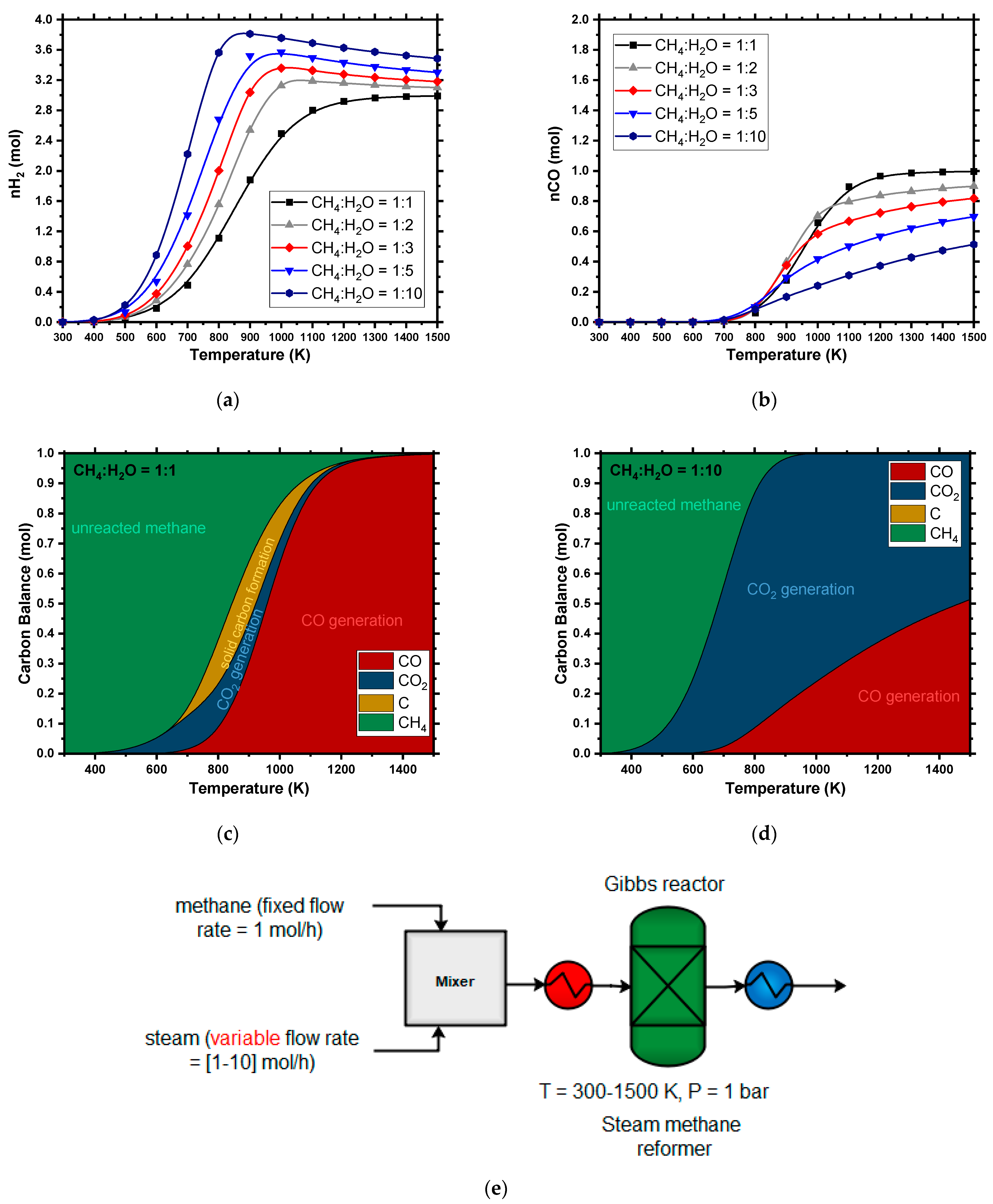
Figure 2 shows the effect of varying the temperature on the equilibrium composition for steam methane reforming. Higher temperatures favor greater H2 and CO production, higher CH4 conversion, lower CO2 in products, and the suppression of solid carbon formation. Higher temperatures also produce higher H2/CO ratios of close to 3:1. In typical industrial applications, a higher H2/CO ratio is favored to prevent coke formation and maintain the high partial pressure of H2 in the downstream synthesis. Compared to POX and dry reforming (DR), SMR produces the highest ratio of syngas (H2/CO), while oxidizing the reformer by CO2 via DR or by O2 via POX does not help to achieve stoichiometric requirements. CH4 conversion and hydrogen generation were enhanced as the steam-to-methane ratio (S:C) increased. As the amount of steam increases, more hydrogen enters the system. Thus, eventually, more hydrogen can be generated. However, increasing the steam also leads to a lower steam conversion and CO yield. As more steam is fed into the system, the WGS reaction (Equation (2)) will shift the equilibrium toward more CO reacting with steam to produce H2 and CO2. Therefore, more steam will increase the conversion of CO, as well as the amount of CO2 produced. Figure 2 illustrates the finding that hydrogen generation continuously increases with temperature until it levels out after a specific temperature, while CO yields increase continuously with temperature. These effects are caused by the competition between the SMR reaction (Equation (1)) and the RWGSR (Equation (9)). At high temperatures (above 1000 K), the RWGS reaction becomes dominant, which consumes the hydrogen that was produced by the SMR reaction and produces carbon monoxide as the temperature increases. A higher steam-to-methane ratio increases hydrogen production; however, it has an adverse effect on the energy input requirement. There is a trade-off between hydrogen production and energy input with the addition of the steam-to-methane ratio.

4.1.2. Partial Oxidation (POX)

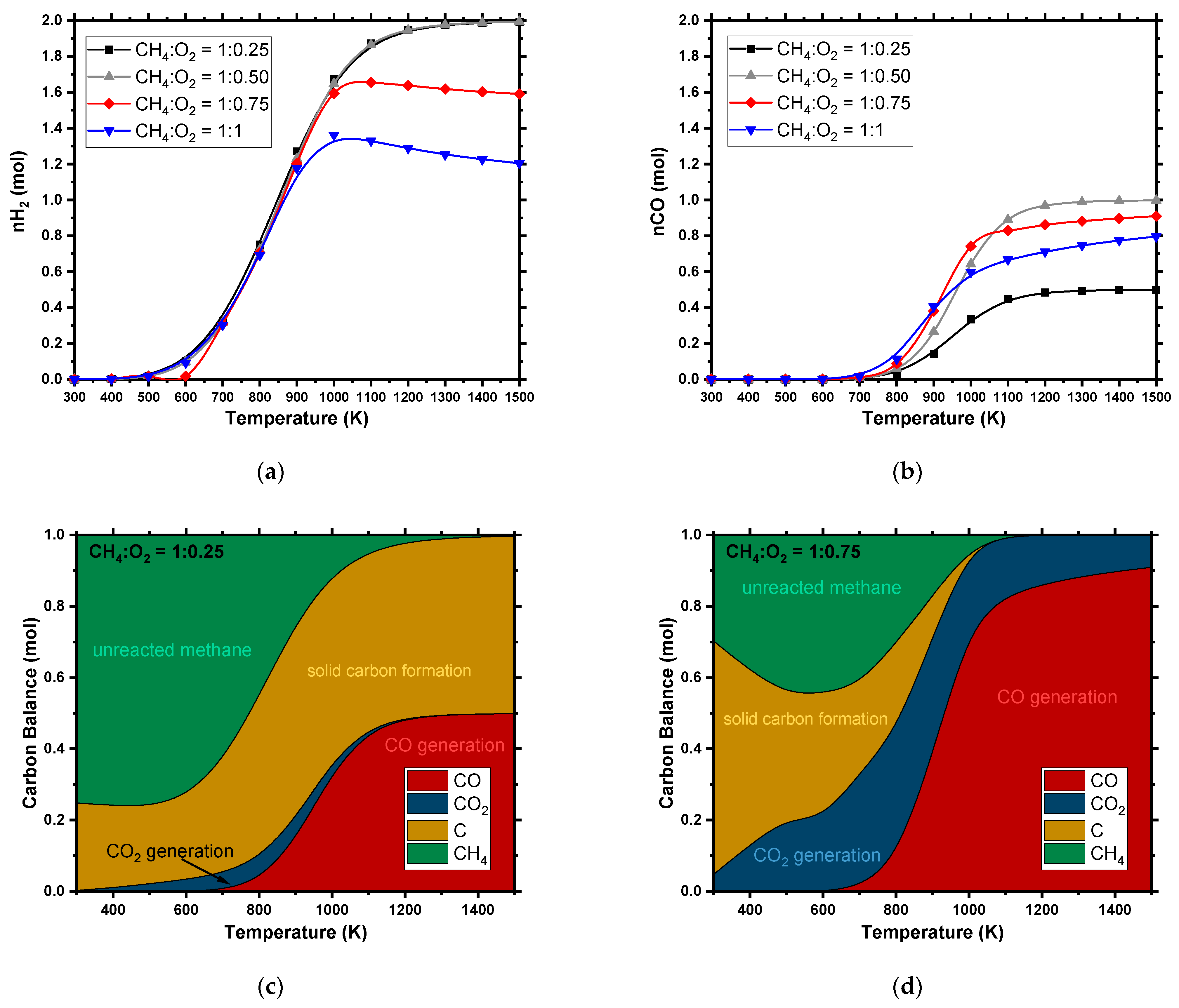
Like SMR, increasing the temperature increases CH4 conversion, H2 generation, and CO generation, and reduces the production of CO2. The maximum H2/CO ratio in this route achieves 2:1 at a higher temperature compared to the SMR ratio of 3:1. At higher oxygen-to-methane ratios, complete combustion is dominant, which reduces the CO and H2 yield and increases the generation of H2O and CO2. In our analysis, the oxygen-to-methane ratio (O:C) varied between 0.25:1 and 1:1. The complete conversion of oxygen took place during partial oxidation and started to decrease as the O:C ratio approached 2:1. Above the 2:1 ratio, complete combustion takes place, and CO2 formation is favored over CO. The same trend occurs for H2 at higher O:C ratios, favoring H2O production rather than H2. Due to the exothermic nature of this reaction, a higher O:C ratio increases the energy output (Figure 3). Solid carbon formation is suppressed by increasing the O:C ratio, which allows the reactor to operate at a relatively low temperature. In order to maintain the syngas ratio above 2.15, this study used WGS to increase hydrogen composition [5]. The syngas was first heated to 572 °C with the co-feed steam to WGS. The steam flow rate was manipulated to adjust the syngas ratio to the desired value of 2.15.

4.1.3. Dry Reforming (DR)

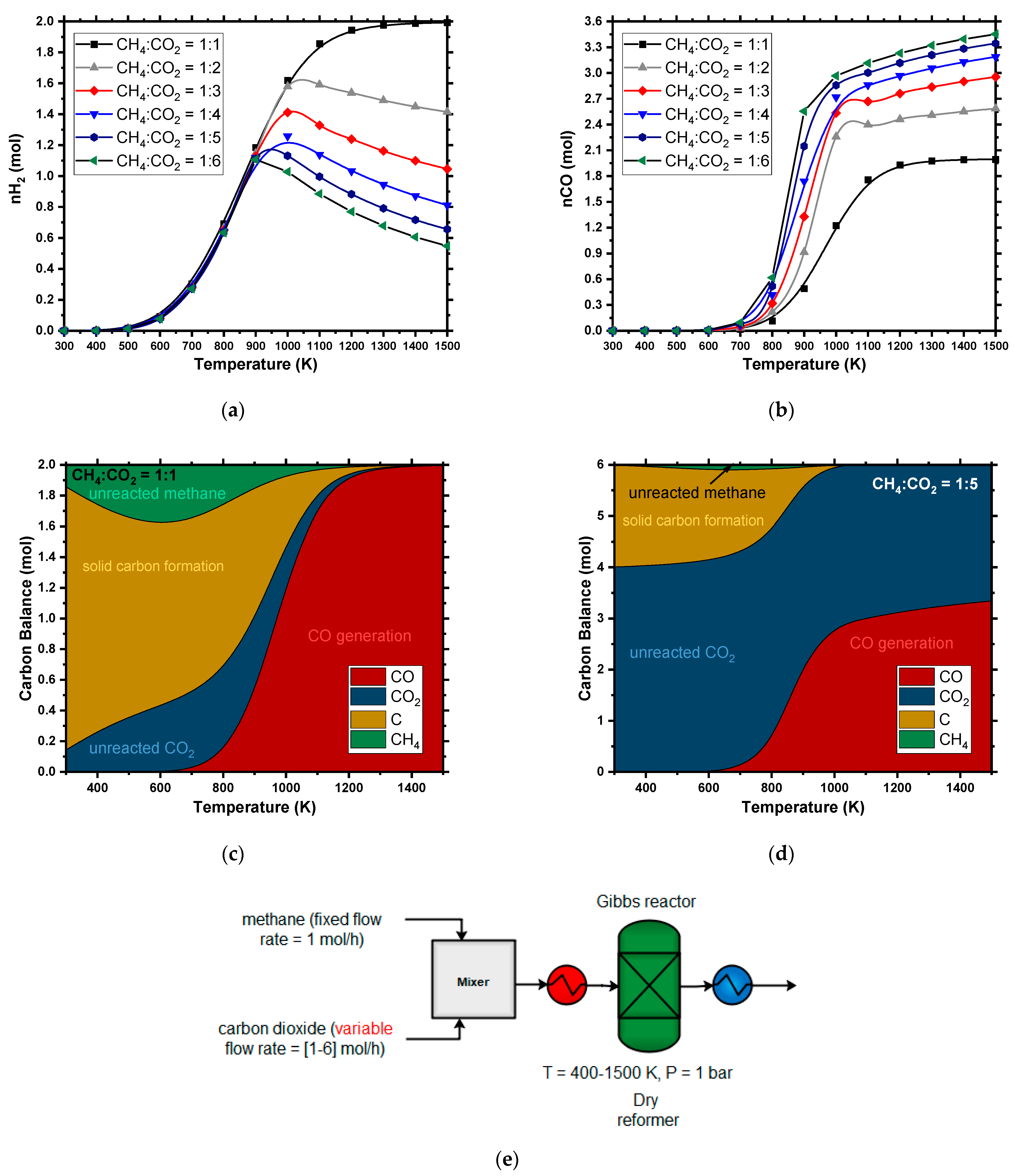
The conversions of CH4 and CO2 were evaluated for a range of temperatures between 300 and 1500 K. A shorter temperature range has been studied by Nematollahi et al. [29]. The conversion of CH4 and CO2 increases with temperature, giving CH4 an estimated conversion of 85%. In the DR process, the generation of hydrogen and carbon monoxide is favored at high temperatures, similar to the SMR and POX processes (Figure 4). The significant difference in this process is that the H2/CO ratio is lower than in the other reforming technologies (close to 1:1), at an initial feed ratio of CH4:CO2 = 1. As the ratio starts to increase (CH4:CO2), the ratio of syngas (H2:CO) reduces, reaching a minimum (close to 1:0.2) at CH4:CO2 = 1:5. Higher temperatures help to suppress carbon formation (Figure 4c,d). This is consistent with previous studies on Gibbs minimization-free energy methods [21,51]. Increasing the temperature increases the hydrogen yield in low syngas ratios, while it prompts a slight rise followed by a decreasing trend in higher syngas ratios. Like SMR and POX, increasing the oxidizer (H2O, O2, or CO2) increases the conversion of CH4. SMR and DR show opposite trends with respect to H2 and CO generation; with more CO2 in the feed, CO generation increases, while H2 generation decreases. The carbon monoxide domination described by endothermic RWGS (Equation (9)), which increases CO2 in the feed, may intensify the RWGS so as to partially consume the hydrogen. While carbon dioxide increases in the reactor outlet with the increasing CH4:CO2 ratio of the feed, the difference decreases in the weight of CO2 between the feed and the products. The limitation of the syngas ratio allows the reformer to operate in a parallel combination of DRM with SMR or DRM with POX. A higher syngas ratio can be achieved by operating the reformer at higher temperatures (>1373 K).

4.1.4. Autothermal Reformer (ATR)

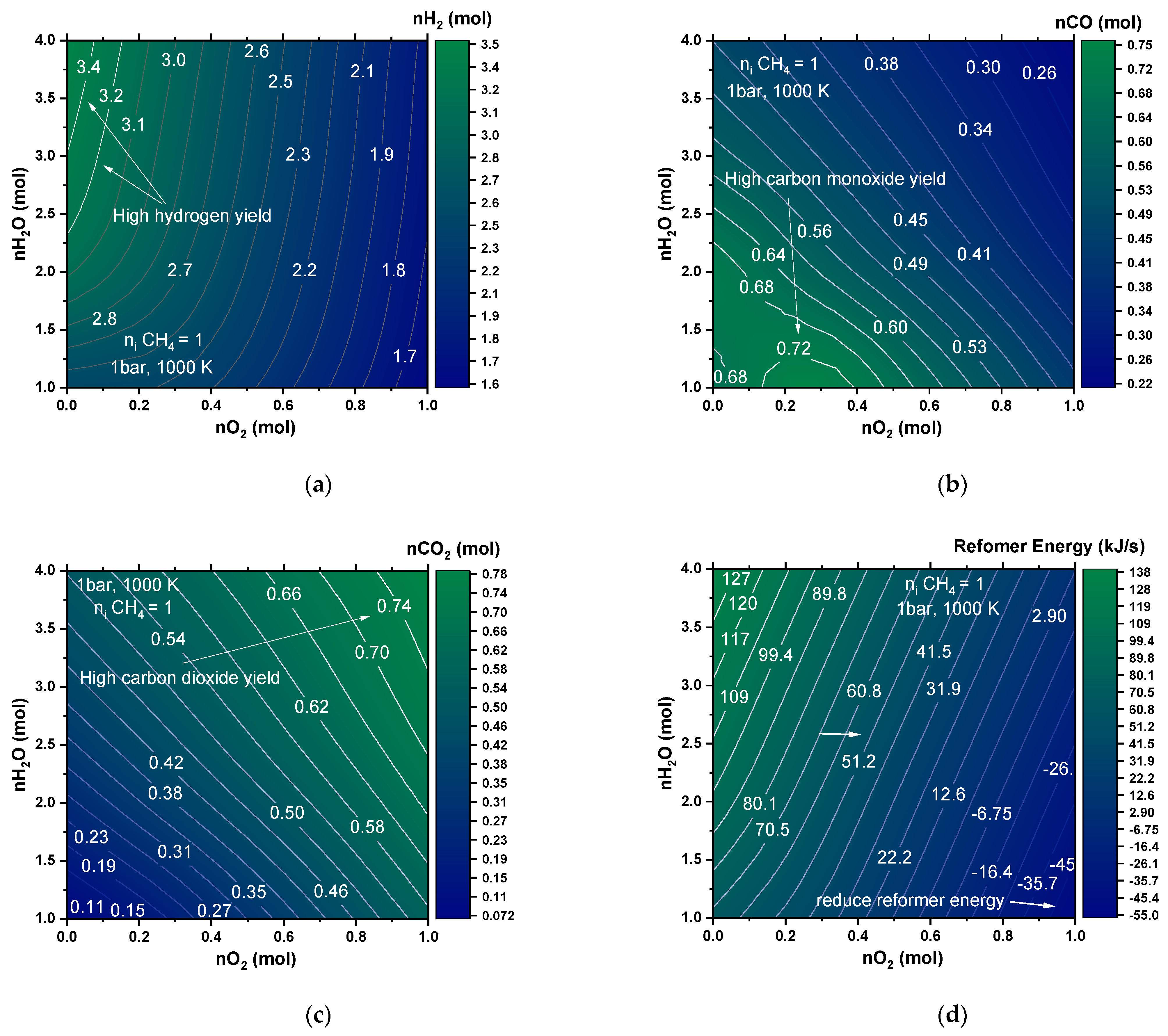
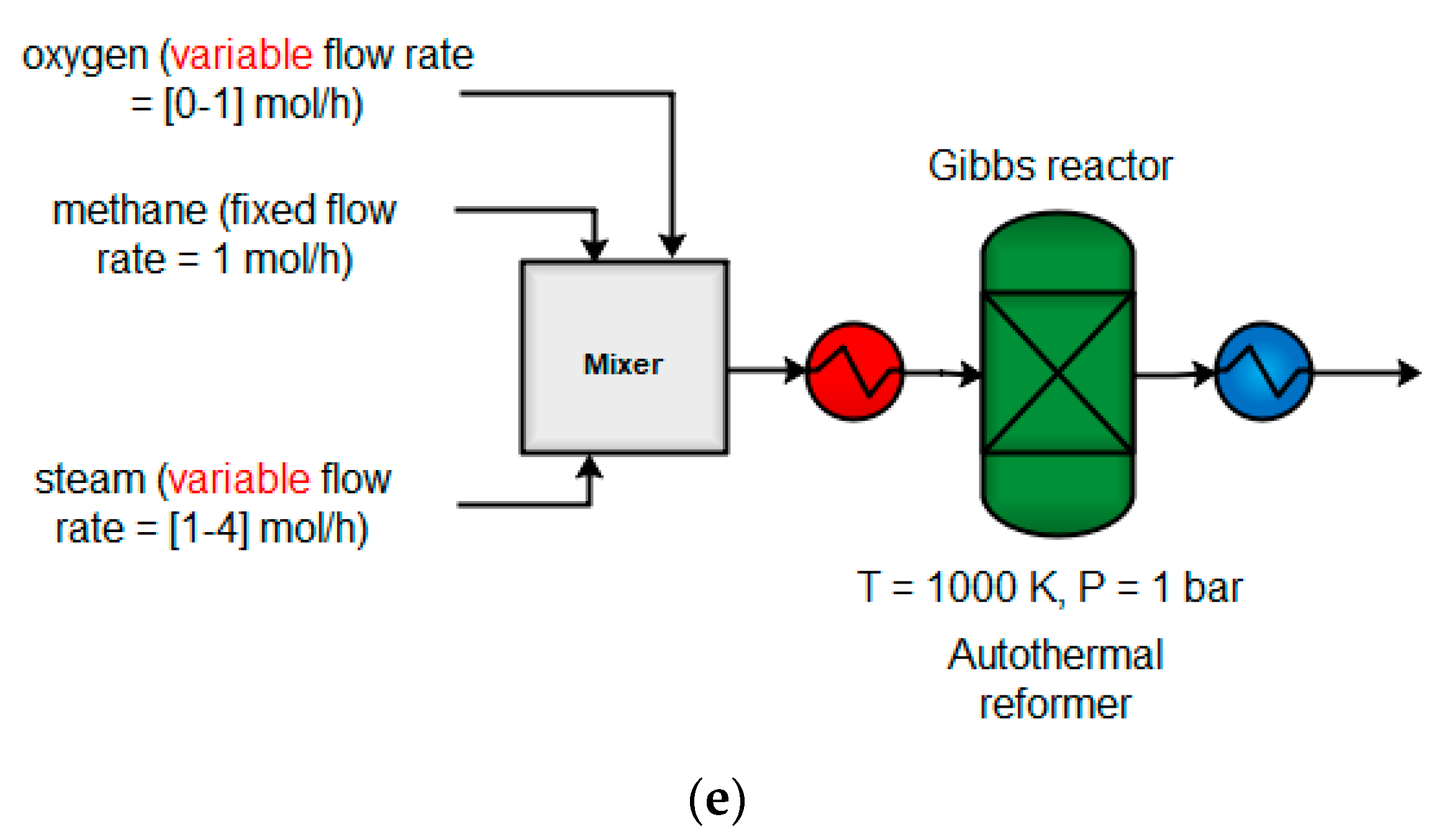
Figure 5 shows the effect of adding different H2O:O2 ratios to the ATR reformer, and the effect on the yield of the reactor (H2, CO, and energy load). Various scenarios carried out by Aspen determined the effect of adding an oxidizer (H2O or O2) to the ATR (Figure 5). It was noted that the addition of H2O or O2 increases the conversion of methane in different H2 and CO yield ratios. The partial oxidation reaction is more favorable than SMR, due to the more exothermic nature of this reaction, which explains the demonstrated O2 conversion. The addition of O2 as an oxidizer increases the amount of CO, while the addition of H2O increases the amount of H2 produced. The enrichment of hydrogen at higher H2O:O2 ratios is expressed by the WGS (Equation (2)). The addition of oxygen may increase the exothermicity of the reaction in most cases; this addition of O2 reaches maximum exothermicity when it is operated at higher O2:H2O ratios (similar to the operating conditions of POX).

4.1.5. Combined Reforming (CR)

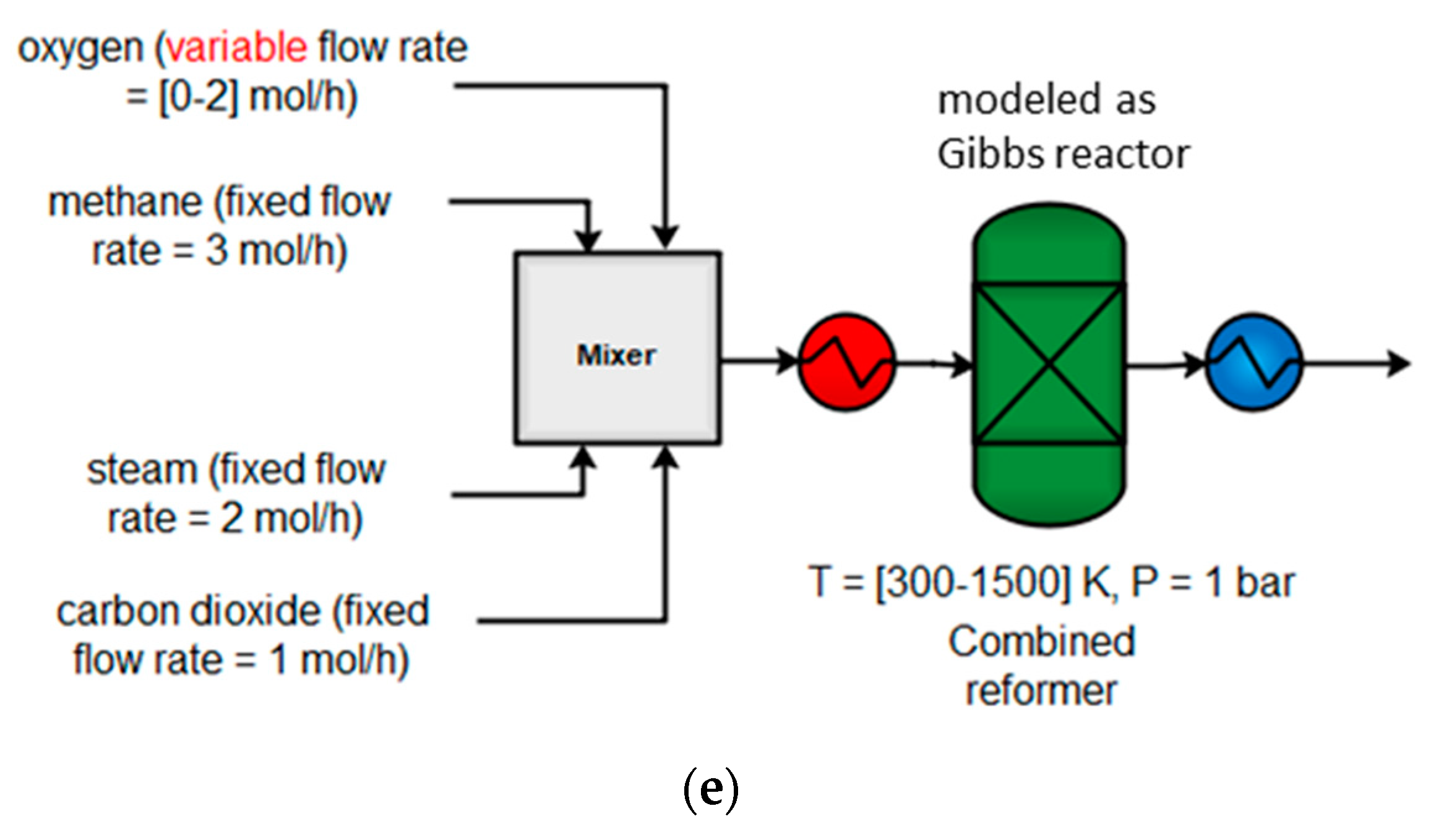
Synergistically combining the benefits of the three reforming processes results in significant carbon dioxide conversion with a low energy requirement, when this process is integrated with an MTO plant [4,5]. Combining reforming technologies, such as SMR, DRM, and POX, in one reactor could provide benefits by increasing the advantages and reducing the drawbacks of each technology [4,23]. The feed of oxidants (CO2, H2O, O2) can be combined in a single reformer CR or implemented in individual reformers (parallel reforming), after which their outputs can be combined. Because methanol requires a 1:2 stoichiometric ratio of CO to H2 and excess hydrogen is produced from SMR, CO2 is injected to react with methane through the DRM (Equation (6)). The overall reaction of the process can be achieved by combining the individual reactions (Equations (1) and (6)), multiplied by a coefficient that ultimately yields the desired product (methanol). The combination of SMR and DRM that should produce the 1:2 stoichiometric ratio of CO to H2 is as follows:
3 CH 4 + 2 H 2 O + CO 2 4 CO + 8 H 2 4 CH 3 OH
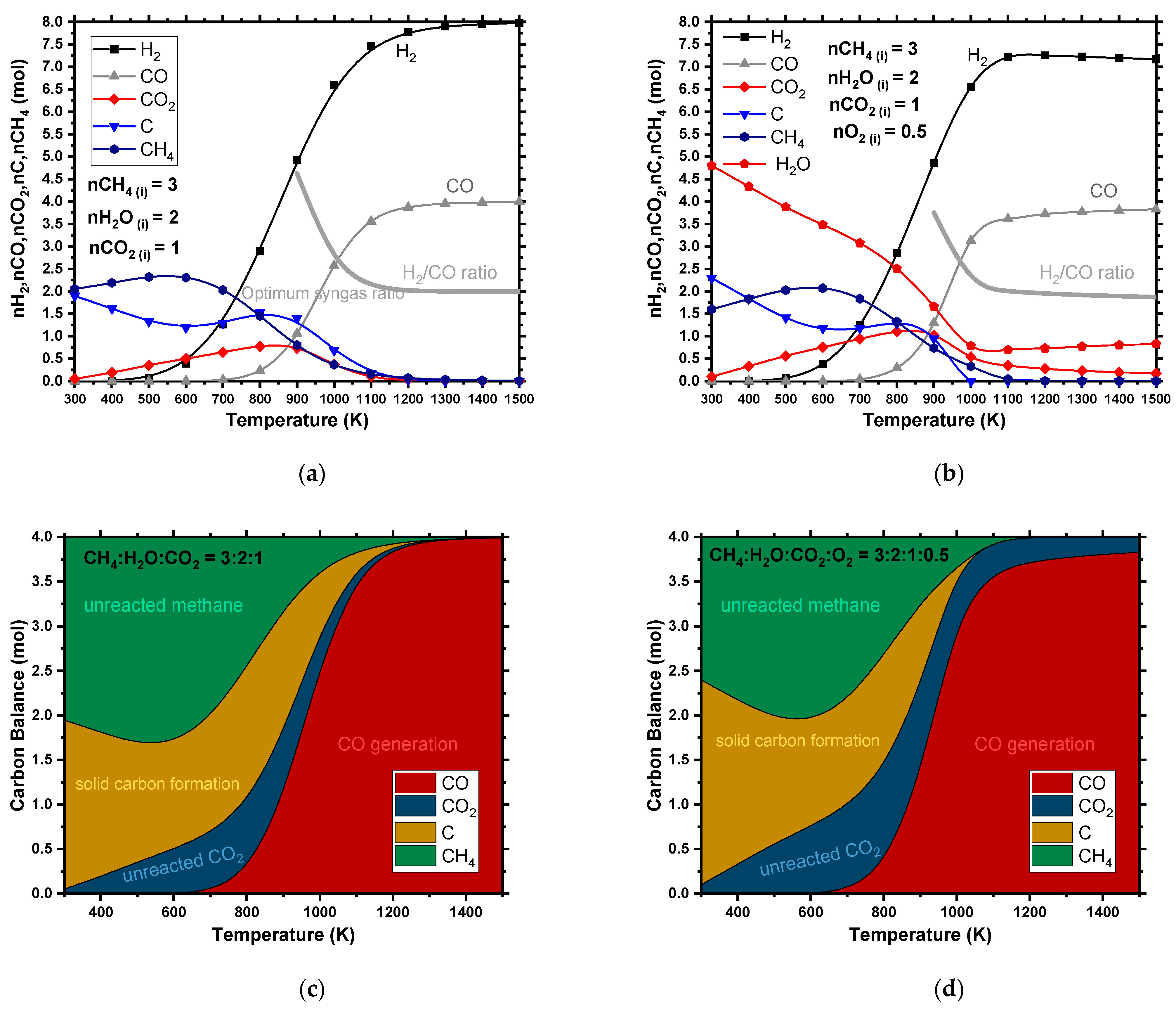
In addition to the combination of SMR and DRM, O2 was added to the reformer to use the energy released from the incomplete reaction of methane in the POX reactor (Equations (3)–(5)) [52]. The addition of O2 to the feed increased CH4 conversion, especially at a temperature below 1100 K (Figure 6c,d), because CH4 becomes a limiting reactant and is consumed by both POX and DRM. The addition of O2 increased CH4 conversion but it also reduced CO2 conversion, as shown in Figure 6c,d, due to the reaction of methane oxidation, which hindered the DRM reaction (Equation (6)). The combination of SMR and DRM achieved a syngas ratio of 2.25 (Figure 6a), while a combination of POX, SMR, and DRM generated a syngas ratio of 1.5 (Figure 6b). The addition of O2 to the combined reformer has been shown to increase the conversion of both CH4 and CO2. [29] Song reported that the catalytic tri-reforming of methane achieved high conversion (> 97%) and high CO2 conversion (around 80%) to produce syngas with ratios of H2/CO = 1.5–2.0 over a Ni catalyst at 1130–1273 K and 1 bar, without carbon formation on the catalyst [22]. Water formation increased as more O2 was added to this process, implying that with high O2 addition, CH4 tends to convert into H2O and CO2 instead of CO and H2. The addition of O2 reduced the ratio of H2:CO at low temperature, due to the influence of POX reactions (Equation (3)) and RWGS (Equation (9)), while at a higher temperature, the syngas ratio was dictated by DRM (Equation (6)) [53]. Increasing the O2 content caused a considerable decrease in CO2 conversion, due to the predominance reaction of CH4 total combustion (Equation (5)), which formed CO2 and H2O [54]. However, carbon formation was reduced to a minimum at 1000 K when O2 was added, compared to results in the case of DRM and SMR (Figure 6c,d). This combined reactor demonstrates the competition of the two oxidants (O2 and CO2) to be the oxidant agent for CH4. It shows that O2 was consumed in all conditions, while CO2 conversion depended on temperature and the addition of O2. Overall, the optimal condition of this section was based on the maximization of CH4 conversion and the production of a suitable H2/CO ratio for methanol synthesis. This comparison illustrates the importance of studying the reforming network configuration to optimize the interlink parameters. Coupling POX with SMR and DRM can facilitate heat transfer between endothermic and exothermic reactions.

4.1.6. Methanol Production

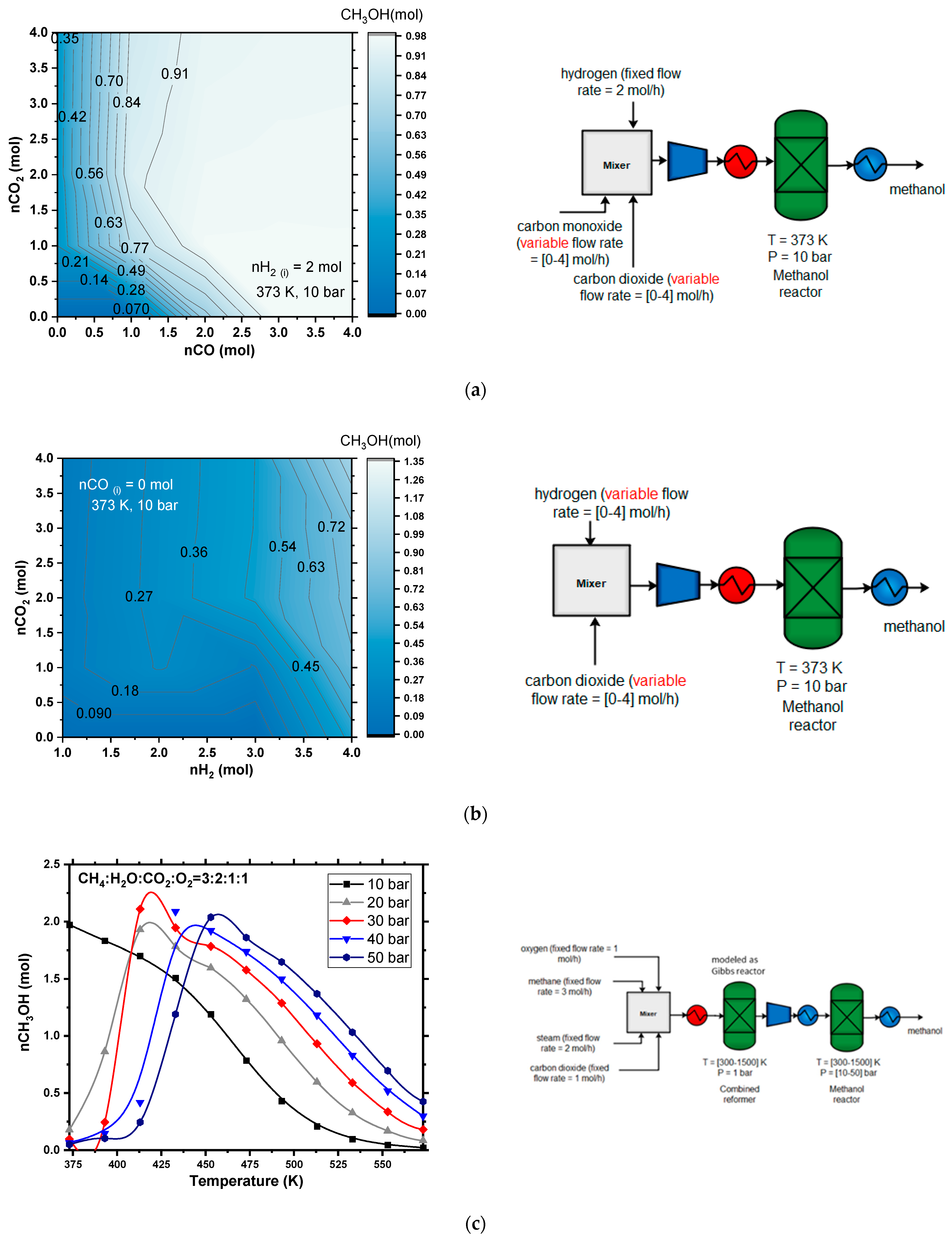
The effect of reactor temperature, pressure, and the stoichiometric ratio of reactants on the methanol yield of this section are shown in Figure 7. For modeling and optimization purposes, reaction conditions of 210–270 °C and 1 bar were used.
The amount of methanol produced increases with temperature and reaches a maximum of approximately 923–973 K. Methanol can be produced from syngas (CO, H2, and CO2) at lower temperatures. An analysis was conducted using an RGIBBS reactor to show the influence of a feed composition of CO2 and CO at a constant H2 feed on the methanol yield, to optimize methanol synthesis for the best combination of syngas feed. The CO2 hydrogenation of methanol and the RWGS reaction were found to be acting competitively. Methanol synthesis is an exothermic reaction, while RWGS is endothermic, and RWGS dominates the process at higher temperatures. By increasing the pressure, CO selectivity decreases, while methanol selectivity increases. The CO hydrogenation of methanol is more favorable than CO2 hydrogenation. Methanol yield increases with increasing CO concentration in the feed, which decreases the selectivity of forming CO from RWGS, due to the presence of CO in the feed. Due to the low-equilibrium conversion to methanol, the recycling of syngas is necessary. As Figure 7 illustrates, CO2 conversion decreases with the addition of CO and even becomes negative with high CO concentrations. This is due to the WGS reaction, which produces additional CO2 in the presence of CO. H2 conversion increases with comparable increases in the addition of CO.
Figure 7c shows two reformers and methanol synthesis reactors that were placed in a series, and the effect of varying reformer inlet conditions was analyzed on the outlet of the methanol reactor. The initial feed ratios of methane, water, and carbon dioxide were similar to the ratio that was used in the combined reformer from Figure 6a,b. The results of these ratios are presented in Figure 7c,d. As shown in Figure 7, a maximum of 2.1 moles of methanol can be achieved at 373 K and 30 bar. The trade-off between pressure and temperature obtained a similar yield.

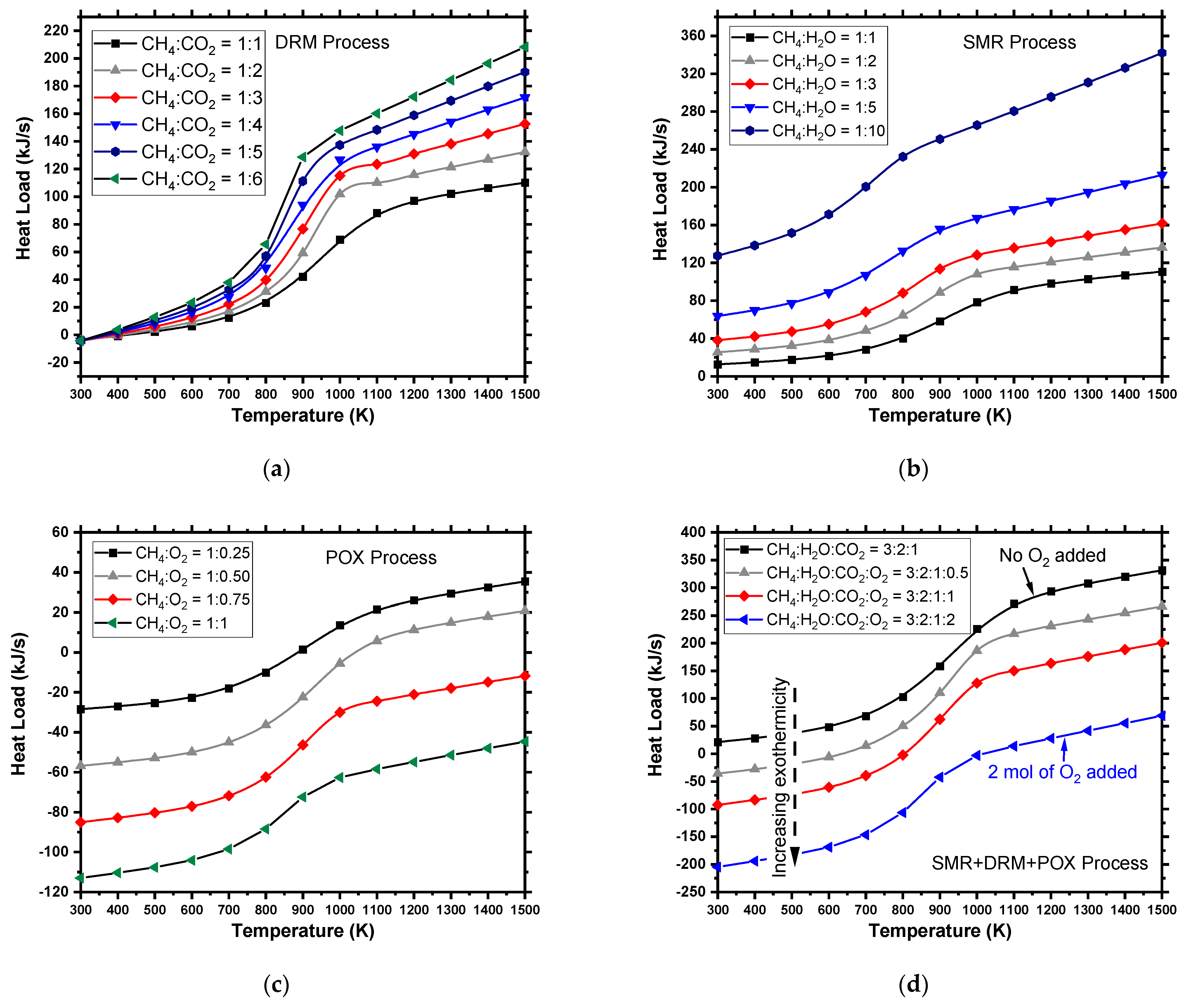
4.2. Material and Energy Balances

Following thermodynamic trends, all three of the process designs discussed in the previous section are assessed for material and energy balances, as presented in Figure 8. The operating energy of each reformer, SMR, DRM, and POX, is shown in Figure 8 at different syngas ratios. The external heat input for each recovery was calculated from the reactor energy balance. A positive HExternal means that the reactor is endothermic and needs heat, and a negative HExternal means that the reactor is exothermic, and that heat must be removed. In this process, the highest demand for the energy requirement was from the SMR, followed by DRM, then the POX reactor. The energy of SMR shows the increased use of steam to obtain a higher syngas ratio, which increases the energy. SMR requires heat supply and produces syngas with a ratio of H2/CO = 1:3, which is relatively higher than that of methanol synthesis. POX is more economical to heat than SMR, the process does not require a catalyst, and it produces syngas with H2/CO = 1:2, which is ideal for methanol synthesis. The results show that POX and ATR demonstrate higher efficiency than SMR in terms of energy usage. However, POX requires high-purity O2, which requires an air separation plant to supply the necessary O2. An ATR reactor, compared to SMR, is moderately cheap to operate. The ATR process is flexible, allowing the option of oxygen or steam. However, the process requires extensive control to ensure proper, robust operation.
The need for a transformative approach to optimizing syngas production has been widely investigated [4,5,23]. There is significant energy loss in the current process in SMR and DRM reactors, due to fuel consumption and low energy recovery. All methods involve high costs and are subject to similar activation mechanisms. The combined reactor integrates SMR, POX, and DRM, and has the advantage of inhabiting catalyst deactivation by oxidizing the coke, which increases catalyst life and process efficiency. Thus, CR was chosen for the methane to olefin plant. For the aspen flowsheet, integrating SMR and POX with DRM is an encouraging concept whereby the undesired CO2 generated from the SMR and POX process is exploited to reform the unreacted methane and achieve autothermal reactions within the integration reactors. In this flowsheet, a methanol synthesis reactor was modeled using a CSTR, with kinetic values obtained from the literature. The methanol produced was then fed into the MTO reactor, which was modeled in this case as three RSTOICH reactors to produce ethylene, propylene, and butene. The split fraction to each reactor was decided based on experiments yield, as illustrated in Table 1 [8,45]. Downstream compression and cryogenic energy separation were not included in this study; however, they result in additional energy loss in the conventional cracking process. Higher ethane conversion could reduce the compression and separation load. However, this approach is not practical, owing to reaction limitations and the tendency of ethylene to undergo secondary reactions that form coke on the tubes’ inner surfaces [55].
The MTO process converts methanol to ethylene, propylene, butene, and water in a set of net-exothermic reactions. MTO offers overall process exothermicity since ethane conversion is not limited by a reaction equilibrium, as is the case with steam cracking (Figure 9). However, the low ethylene yield (<20% ethylene) and the considerable ethane byproducts require intensive downstream separation and recycling of the unconverted methane and ethane [56,57]. Figure 8 shows a section-wise comparison of energy consumption. The simulation indicates that the energy demand is higher for steam cracking than in MTO. It should be noted that both the MTO and steam-cracking processes require intensive separation and co-produce propylene and butene. These co-products can either be credited to the process as fuels or purified and sold as byproducts (Figure 10).

4.3. Economic Evaluation

Olefin plant economics were estimated based on the assumption of 330 operating days per year, a tax rate of 30%, and a 10-year linear depreciation scheme to calculate the annualized fixed cost [58,59]. The selling price for ethylene was set at USD 1200/ton, and, for the propylene by-product, the price was USD 1340/ton. The feedstock market and product prices are listed in Table 2. The products, ethylene and propylene, were assumed to be sold from the plant gate and the prices did not include the costs of transportation to end-users. The annual operating cost (AOC) included operating and maintenance costs for steam (Csteam), solvent, refrigerant (Crefri), cooling/boiling water (Cwater), and electricity (Celectric), as given by the following equation:
AOC = LPS , MPS C steam + CW , BW C water + C electric + C refri
The total capital investment (TCI) was estimated using the six-tenths rule, based on data obtained for methanol and olefin plants. The profitability of each process was estimated using a return on investment (ROI) equation, as follows:
ROI = ( Annual   incomes Operating   costs Annual   fixed   cost ) × ( 1 tax   rate ) + Anuual   fixed   cost   TCI
The cost of shale gas was assumed to be USD 3.50/kscf. The catalysts’ lifetime was not considered as part of the operating cost estimation.
Based on the simulation results, capital costs, and variable operating costs of most of the process equipment (i.e., reactors, flash tanks, and distillation columns), in addition to fixed operating costs for the plant (i.e., labor, insurance, and maintenance), were estimated using the Aspen Process Economic Analyzer. Vacuum pumps are not standard simulation blocks in Aspen and were, therefore, sized separately. Feedstock and utilities were assumed to be available at the prices listed in Table 3. The total capital and operating costs for the process are presented in Table 4. For a base-case plant size capable of processing 1000 ton/yr−1 of methane, the total installed equipment costs were USD 16.4 million. AOC was calculated to be 55.31 USD MM/year for the current case.

4.4. Energy Integration

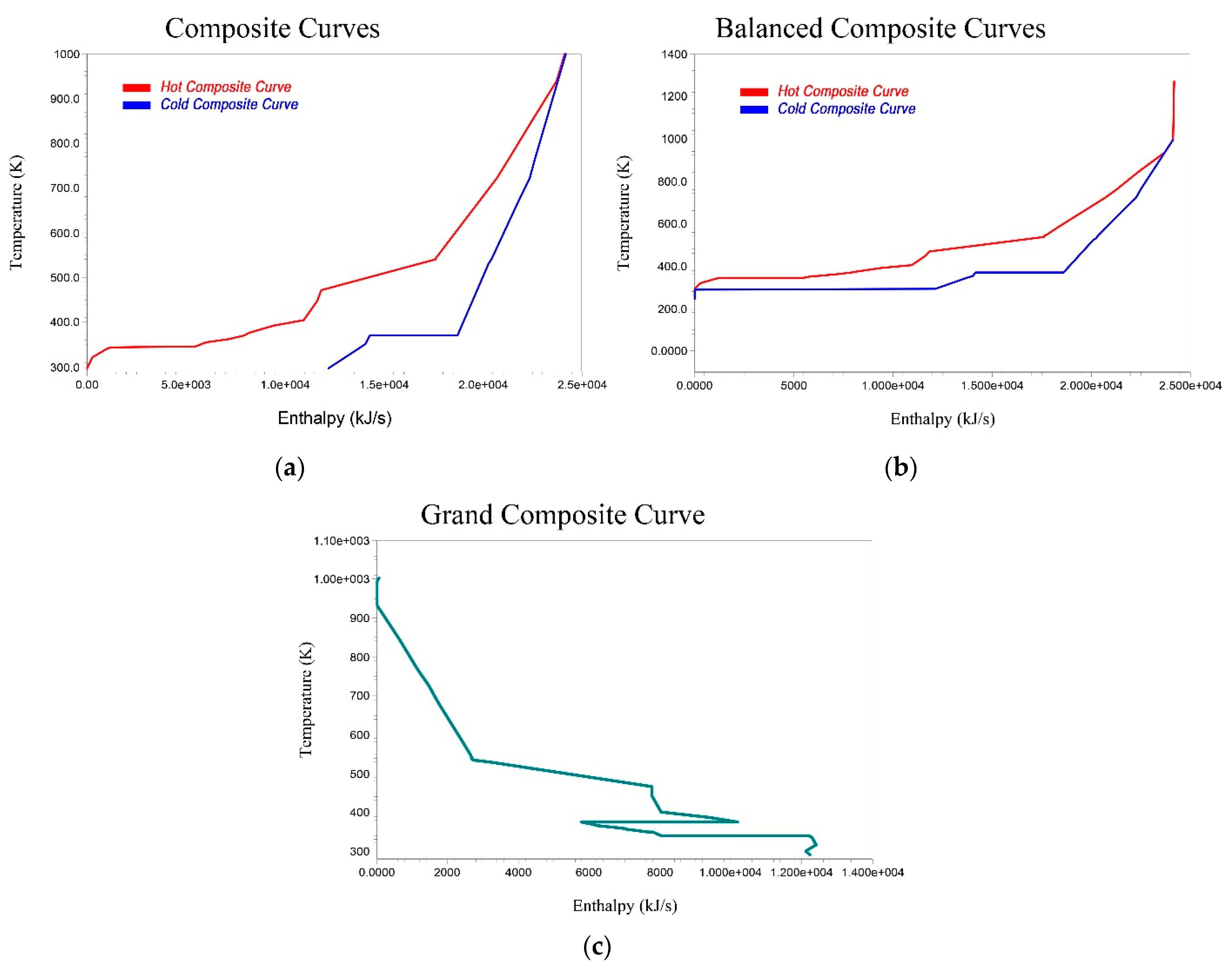
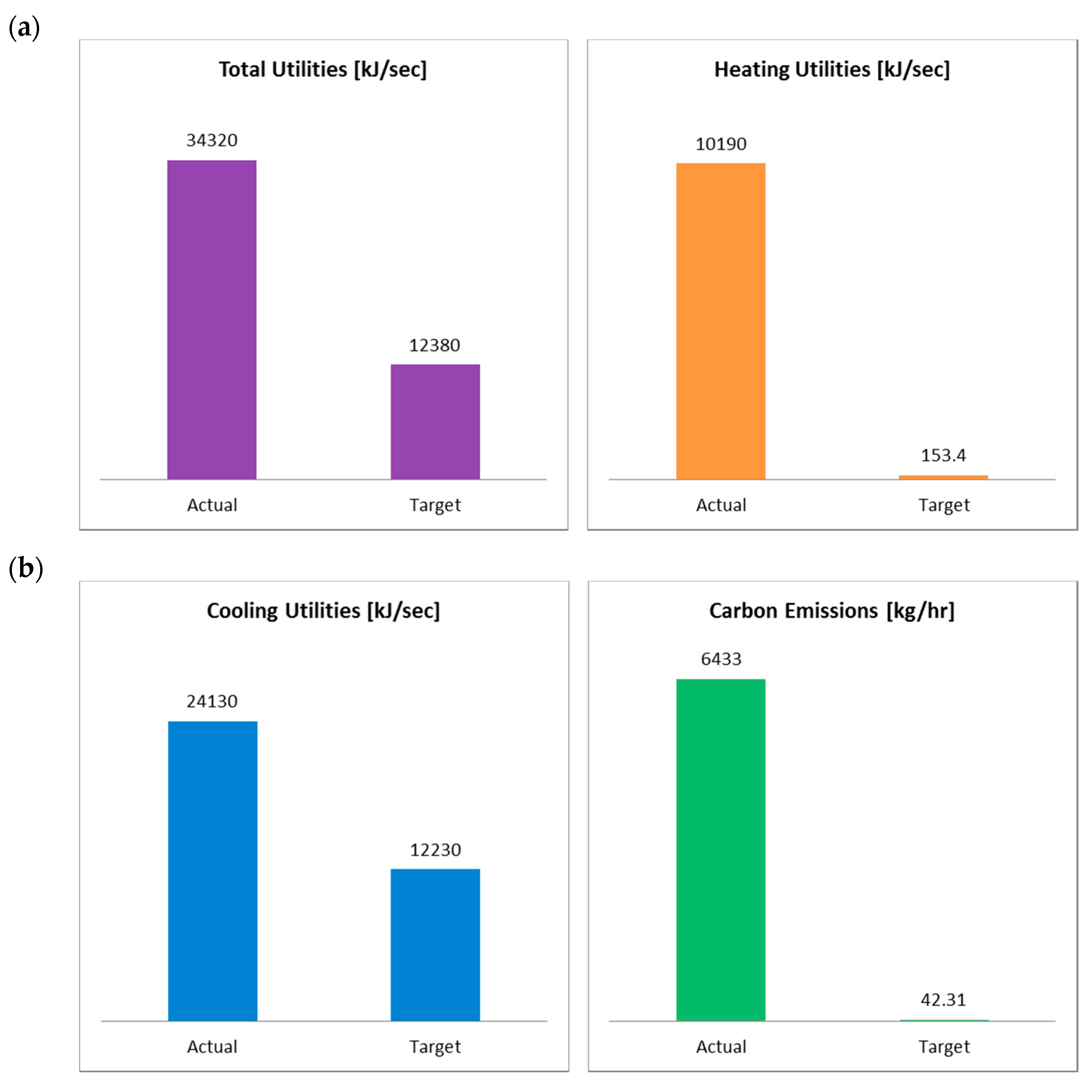
The heat integration of each process design was investigated using the Aspen Energy Analyzer. Thermal pinch analysis was performed on the base case to identify the recovery of heat within the process streams. Pinch analysis is a HEN optimization algorithm that can be used to reduce the energy consumption in a process by setting feasible energy targets, achieving them by optimizing the heat recovery systems, energy supply methods, and process operating conditions for energy reduction [61]. The composite curve is obtained by summing all the heat loads over a temperature range. The composite curve is presented in Figure 11. The process fulfilled several heating and cooling duties. The heat exchanger took the inlet stream and heated it to 1000 K before entering the CR reactor. The heat recovery exchangers cooled the syngas mixture stream from the CR reactor to 323 K and then compressed the mixture to a pressure of 40 bar. The condensed liquid was separated from the syngas stream in the flash column; then, the gas stream was heated again in the methanol heat exchanger to 543 K before the stream entered the methanol reactor. The product outlet was then sent to cool exchangers, to cool the product to 323 K. The heat load for each piece of equipment used in the process flow sheet is shown in Figure 5. The operating energy of this process can be reduced by using heat integration. The minimum hot and cold utility requirements were 153 kJ/s and 12,230 kJ/s, respectively. High values of hot utility were due to the large heating requirement of the fired heater and reboiler. The high cold utility was due to the reactor effluent cooler and condenser. There was a potential for heat exchange in the temperature range of 273–1000 K. Therefore, the composite curve can be further optimized for the heat exchanger network to provide the lowest energy consumption for the external utilities. Given these high energy values for the utilities, an integrated case was developed to reduce the energy consumption from external sources by utilizing some of the process heat. For this modification, the combined reactor effluent cooling duty was reduced. The syngas leaving the reformer had a hot stream to serve as effective heat recovery.
Figure 11c shows the grand composite curve developed in the process. The analysis indicates that the target values can be reduced to minimal values based on heat loads presented in Table 5. The cooling utilities can be reduced by 39.3%, and the heating requirement of 98.5% can be reduced by 95%. Such reductions in energy requirements can provide savings equivalent to 2.79 USD MM/year.
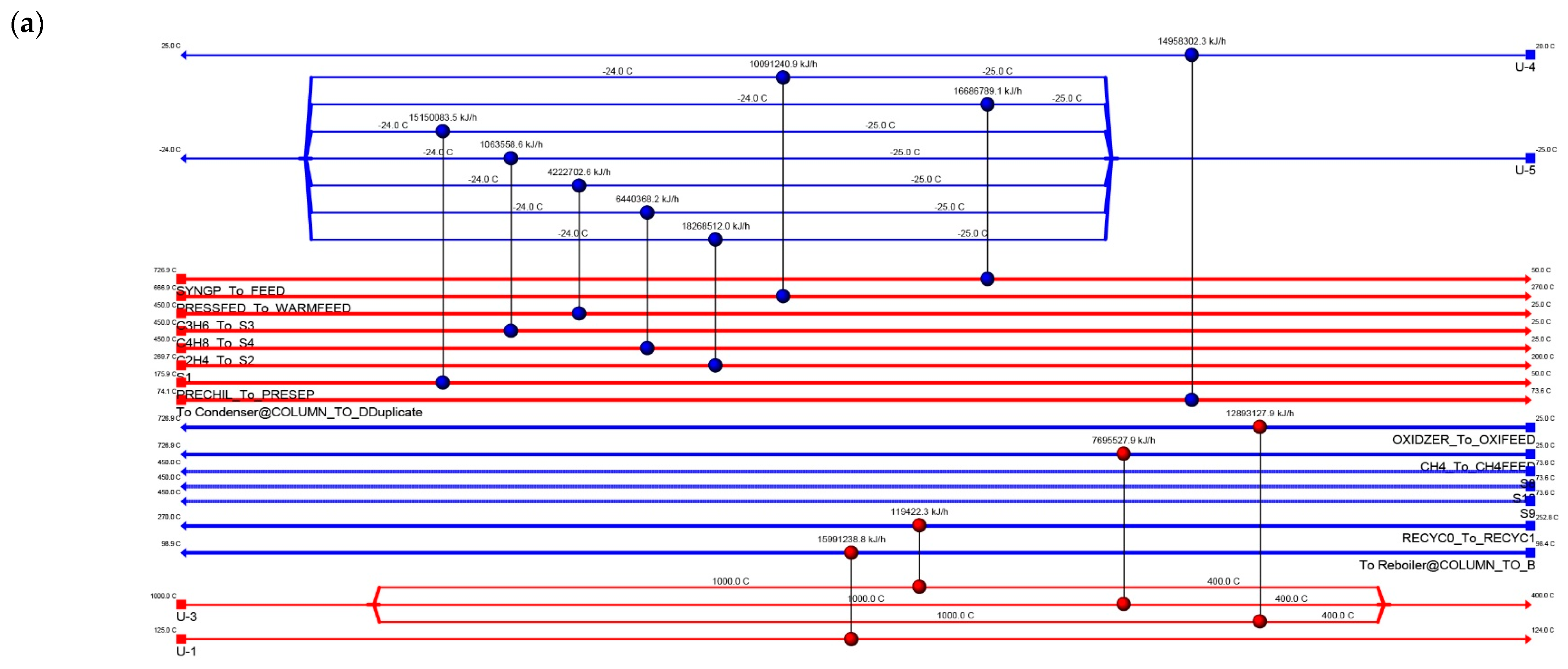
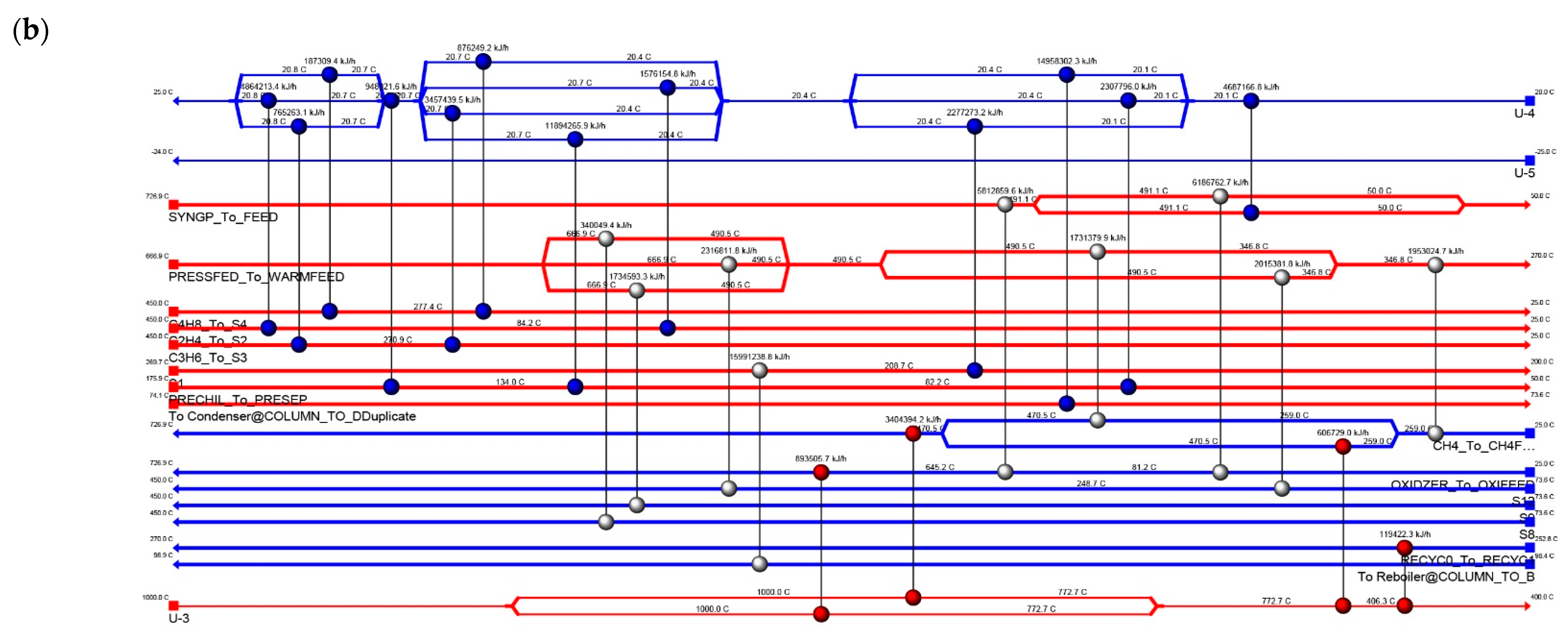
In addition to the heat exchange network, illustrated in Figure 11b, the methanol reactor has the potential for mass and heat integration with a methane reformer reactor [24]. The heat released from the exothermic methanol reactor can partially supply the heat required for the endothermic methane reforming reaction (Figure 11). Another integration is to release heat from the MTO reactor, which can be applied to the MTO feed heat exchanger. Figure 12 illustrates the existing network of heat exchangers. The blue lines at the top represent cooling utility streams. The broadband of red lines indicates hot process streams, whereas the narrower blue lines indicate cold process streams. The red section at the bottom represents the heating utility streams. The alternative selection process is guided by several criteria, including energy savings, minor HEN modifications, and low capital investment. One retrofit option was suggested in this study, which requires some modifications, is cost-effective, and is practically feasible. The recommended option is predicated on the possibility of recovering the enormous amount of energy wasted in the heat exchangers. This option entails the addition of new heat exchangers that will exchange heat between the hot and cold streams of the plant. The new heat exchanger’s location was determined using pinch analysis and the optimization of the existing grid under the constraints. This option’s capital cost and economic impact were calculated. The economic evaluation is based on the data presented in Table 6 and Figure 13.

4.5. Environmental Impact

We examined the CO2 emissions to analyze the environmental impact associated with each process. Thus, the carbon emissions were calculated based on the actual and energy-related CO2 emissions [9]. Burning fuels can directly generate CO2 emissions. The CO2 equivalent of the outlet streams was obtained from Aspen Plus simulations, while CO2 emissions from electricity consumption were calculated using a factor of 0.73 MT of CO2/MW [8]. The emission from heating utilities was estimated using the EPA (Environmental Protection Agency) energy method of stationary combustion [62]. The resulting CO2 emissions of the process are 6433 kg/h. Combining DRM and SMR can produce syngas with H2:CO close to a ratio of 2:1, and will result in minimal CO2 emissions. Moreover, external heat is reduced and is consistent with CO2 emissions. The analysis reveals the differences in environmental impact after applying energy integration, which resulted in CO2 reduction by 99.24% to 43.2 kg/h.

5. Conclusions

Technical analyses for ethylene, propylene, and other products produced from methane were presented herein. Four reforming technologies were analyzed to produce syngas, partial oxidation (PO), SMR, autothermal reforming (ATR), and CR. Of all the cases considered in this study, we found the scenario using CR and MTO to be the most promising route to producing ethylene, with low energy demand and CO2 emissions. There is a >50% reduction in the proposed route’s energy consumption when compared with the conventional reforming units. Aspen Plus was used to assess the performance of each option. The equilibrium conversion of CH4 was thermodynamically favored, between 700 and 1100 K. The highest yield of H2 was obtained at CH4/CO2, CH4/O2 ratios of 1.0, 4.0, and a temperature of 1100 K, respectively. The results show that POX and ATR demonstrate higher efficiency than SMR in terms of energy usage. The impact of each process on the carbon footprint was evaluated, and the overall CO2 emissions for a specific H2/CO ratio were compared. The comparisons indicate that DRM has a negative carbon footprint at a low syngas ratio of 1 and below. More carbon emissions can be reduced by integrated heating and cooling utilities, resulting in CO2 reduction by 99.24% from 6433 to 43.2 kg/h. This study revealed that the success of a future sustainable hydrogen economy is based on the development of integrated and improved technologies to provide efficient transition toward low-carbon alternatives. In this perspective, a detailed comparison of conventional and advanced olefin pathways has been provided, which showed that, in addition to renewable energy sources, methane upcycling should also be conducted to fill the gap during the low carbon economy transition. Therefore, the use of natural gas and coal in the petrochemical industry provides a major opportunity to contain carbon within newly formed molecules. Consequently, value-added chemicals are provided from natural gas, and the release of CO2 into the atmosphere is avoided. The use of methane gas in the production of olefins and other chemicals has strong potential to be a game-changer in the chemical industry. Once syngas is produced, it can be transformed into numerous intermediates and products. Examples of chemicals that can be transformed into products include methanol, ethylene, propylene, benzene, and liquid transportation fuels.

Funding

This research received no external funding.

Conflicts of Interest

The authors declare no conflict of interest.

References

  1. World Energy Outlook 2021; International Energy Agency: Paris, France, 2021. [CrossRef]
  2. York, A.P.E.; Xiao, T.; Green, M.L.H.; Claridge, J.B. Methane oxyforming for synthesis gas production. Catal. Rev. 2007, 49, 511–560. [Google Scholar] [CrossRef]
  3. Martinez-Gomez, J.; Sánchez-Ramírez, E.; Quiroz-Ramírez, J.J.; Segovia-Hernandez, J.G.; Ponce-Ortega, J.M.; El-Halwagi, M.M. Involving economic, environmental and safety issues in the optimal purification of biobutanol. Process Saf. Environ. Prot. 2016, 103, 365–376. [Google Scholar] [CrossRef]
  4. Noureldin, M.M.B.; Elbashir, N.O.; Gabriel, K.J.; El-Halwagi, M.M. A process integration approach to the assessment of CO2 fixation through dry reforming. ACS Sustain. Chem. Eng. 2015, 3, 625–636. [Google Scholar] [CrossRef]
  5. Gabriel, K.J.; Linke, P.; Jiménez-Gutiérrez, A.; Martínez, D.Y.; Noureldin, M.; El-Halwagi, M.M. Targeting of the water-energy nexus in gas-to-liquid processes: A comparison of syngas technologies. Ind. Eng. Chem. Res. 2014, 53, 7087–7102. [Google Scholar] [CrossRef]
  6. Ehlinger, V.M.; Gabriel, K.J.; Noureldin, M.M.B.; El-Halwagi, M.M. Process design and integration of shale gas to methanol. ACS Sustain. Chem. Eng. 2014, 2, 30–37. [Google Scholar] [CrossRef] [Green Version]
  7. Julián-Durán, L.M.; Ortiz-Espinoza, A.P.; El-Halwagi, M.M.; Jiménez-Gutiérrez, A. Techno-economic assessment and environmental impact of shale gas alternatives to methanol. ACS Sustain. Chem. Eng. 2014, 2, 2338–2344. [Google Scholar] [CrossRef]
  8. Ortiz-Espinoza, A.P.; Noureldin, M.M.B.; El-Halwagi, M.M.; Jiménez-Gutiérrez, A. Design, simulation and techno-economic analysis of two processes for the conversion of shale gas to ethylene. Comput. Chem. Eng. 2017, 107, 237–246. [Google Scholar] [CrossRef]
  9. Jasper, S.; El-Halwagi, M. A techno-economic comparison between two methanol-to-propylene processes. Processes 2015, 3, 684–698. [Google Scholar] [CrossRef]
  10. Pérez-Uresti, S.I.; Adrián-Mendiola, J.M.; El-Halwagi, M.M.; Jiménez-Gutiérrez, A. Techno-economic assessment of benzene production from shale gas. Processes 2017, 5, 33. [Google Scholar] [CrossRef]
  11. Bao, B.; El-Halwagi, M.M.; Elbashir, N.O. Simulation, integration, and economic analysis of gas-to-liquid processes. Fuel Process. Technol. 2010, 91, 703–713. [Google Scholar] [CrossRef] [Green Version]
  12. An, Y.; Lin, T.; Yu, F.; Yang, Y.; Zhong, L.; Wu, M.; Sun, Y. Advances in direct production of value-added chemicals via syngas conversion. Sci. China Chem. 2017, 60, 887–903. [Google Scholar] [CrossRef]
  13. Guo, X.; Fang, G.; Li, G.; Ma, H.; Fan, H.; Yu, L.; Ma, C.; Wu, X.; Deng, D.; Wei, M.; et al. Direct, nonoxidative conversion of methane to ethylene, aromatics, and hydrogen. Science 2014, 344, 616–619. [Google Scholar] [CrossRef] [PubMed]
  14. He, C.; You, F. Toward more cost-effective and greener chemicals production from shale gas by integrating with bioethanol dehydration: Novel process design and simulation-based optimization. AIChE J. 2015, 61, 1209–1232. [Google Scholar] [CrossRef]
  15. Bao, J.; Yang, G.; Yoneyama, Y.; Tsubaki, N. Significant advances in C1 catalysis: Highly efficient catalysts and catalytic reactions. ACS Catal. 2019, 9, 3026–3053. [Google Scholar] [CrossRef]
  16. Spivey, J.J.; Hutchings, G. Catalytic aromatization of methane. Chem. Soc. Rev. 2014, 43, 792–803. [Google Scholar] [CrossRef]
  17. Taifan, W.; Baltrusaitis, J. CH4 conversion to value added products: Potential, limitations and extensions of a single step heterogeneous catalysis. Appl. Catal. B Environ. 2016, 198, 525–547. [Google Scholar] [CrossRef]
  18. Cho, W.; Song, T.; Mitsos, A.; McKinnon, J.T.; Ko, G.H.; Tolsma, J.E.; Denholm, D.; Park, T. Optimal design and operation of a natural gas tri-reforming reactor for DME synthesis. Catal. Today 2009, 139, 261–267. [Google Scholar] [CrossRef]
  19. Kalamaras, C.M.; Efstathiou, A.M. Hydrogen production technologies: Current state and future developments. Conf. Pap. Energy 2013, 2013, 1–9. [Google Scholar] [CrossRef] [Green Version]
  20. Wilhelm, D.J.; Simbeck, D.R.; Karp, A.D.; Dickenson, R.L. Syngas production for gas-to-liquids applications: Technologies, issues and outlook. Fuel Process. Technol. 2001, 71, 139–148. [Google Scholar] [CrossRef]
  21. Rostrup-Nielsen, J.R.; Bak Hansen, J.H. CO2-reforming of methane over transition metals. J. Catal. 1993, 144, 38–49. [Google Scholar] [CrossRef]
  22. Song, C.; Pan, W. Tri-reforming of methane: A novel concept for catalytic production of industrially useful synthesis gas with desired H2/CO ratios. Catal. Today 2004, 98, 463–484. [Google Scholar] [CrossRef]
  23. Noureldin, M.M.B.; Elbashir, N.O.; El-Halwagi, M.M. Optimization and selection of reforming approaches for syngas generation from natural/shale gas. Ind. Eng. Chem. Res. 2014, 53, 1841–1855. [Google Scholar] [CrossRef]
  24. Godini, H.R.; Xiao, S.; Jašo, S.; Stünkel, S.; Salerno, D.; Son, N.X.; Song, S.; Wozny, G. Techno-economic analysis of integrating the methane oxidative coupling and methane reforming processes. Fuel Process. Technol. 2013, 106, 684–694. [Google Scholar] [CrossRef]
  25. World Energy Outlook 2019; OECD; International Energy Agency: Paris, France, 2019. [CrossRef]
  26. Martinez-Gomez, J.; Nápoles-Rivera, F.; Ponce-Ortega, J.M.; El-Halwagi, M.M. Optimization of the production of syngas from shale gas with economic and safety considerations. Appl. Therm. Eng. 2017, 110, 678–685. [Google Scholar] [CrossRef]
  27. Niziolek, A.M.; Onel, O.; Floudas, C.A. Production of benzene, toluene, and the xylenes from natural gas via methanol. Comput. Aided Chem. Eng. 2016, 38, 2349–2354. [Google Scholar]
  28. He, C.; You, F. Shale gas processing integrated with ethylene production: Novel process designs, exergy analysis, and techno-economic analysis. Ind. Eng. Chem. Res. 2014, 53, 11442–11459. [Google Scholar] [CrossRef]
  29. Nematollahi, B.; Rezaei, M.; Khajenoori, M. Combined dry reforming and partial oxidation of methane to synthesis gas on noble metal catalysts. Int. J. Hydrogen Energy 2011, 36, 2969–2978. [Google Scholar] [CrossRef]
  30. Meissner, H.P.; Kusik, C.L.; Dalzell, W.H. Equilibrium composition with multiple reactions. Ind. Eng. Chem. Fundam. 1969, 8, 659–665. [Google Scholar] [CrossRef]
  31. Foust, T.D.; Aden, A.; Dutta, A.; Phillips, S. An economic and environmental comparison of a biochemical and a thermochemical lignocellulosic ethanol conversion processes. Cellulose 2009, 16, 547–565. [Google Scholar] [CrossRef]
  32. Phillips, S.; Aden, A.; Jechura, J.; Dayton, D. Thermochemical Ethanol via Indirect Gasification and Mixed Alcohol Synthesis of Lignocellulosic Biomass; Ethanol Biofuel Production, National Renewable Energy Lab (NREL): Golden, CO, USA, 2010. [Google Scholar]
  33. Asaro, M.; Smith, R.M.; Davis, B.H. Gas to Liquid Technologies. In Encyclopedia of Sustainability Science and Technology; Meyers, R.A., Ed.; Springer: New York, NY, USA, 2017; pp. 1–48. [Google Scholar] [CrossRef]
  34. Steynberg, A.; Dry, M. Fischer-Tropsch Technology; Elsevier Science: Amsterdam, The Netherlands, 2004. [Google Scholar]
  35. Aasberg-Petersen, K.; Dybkjær, I.; Ovesen, C.V.; Schjødt, N.C.; Sehested, J.; Thomsen, S.G. Natural gas to synthesis gas—Catalysts and catalytic processes. J. Nat. Gas Sci. Eng. 2011, 3, 423–459. [Google Scholar] [CrossRef]
  36. Snoeck, J.W.; Froment, G.F.; Fowles, M. Steam/CO2 reforming of methane. Carbon filament formation by the Boudouard reaction and gasification by CO2, by H2, and by steam: Kinetic study. Ind. Eng. Chem. Res. 2002, 41, 4252–4265. [Google Scholar] [CrossRef]
  37. Tijm, P.J.A.; Waller, F.J.; Brown, D.M. Methanol technology developments for the new millennium. Appl. Catal. A Gen. 2001, 221, 275–282. [Google Scholar] [CrossRef]
  38. Vanden Bussche, K.M.; Froment, G.F. A steady-state kinetic model for methanol synthesis and the water gas shift reaction on a commercial Cu/ZnO/Al2O3 catalyst. J. Catal. 1996, 161, 1–10. [Google Scholar] [CrossRef]
  39. Arora, S.S.; Bhan, A. The critical role of methanol pressure in controlling its transfer dehydrogenation and the corresponding effect on propylene-to-ethylene ratio during methanol-to-hydrocarbons catalysis on H-ZSM-5. J. Catal. 2017, 356, 300–306. [Google Scholar] [CrossRef]
  40. Lee, Y.J.; Baek, S.C.; Jun, K.W. Methanol conversion on SAPO-34 catalysts prepared by mixed template method. Appl. Catal. A Gen. 2007, 329, 130–136. [Google Scholar] [CrossRef]
  41. Chen, J.Q.; Bozzano, A.; Glover, B.; Fuglerud, T.; Kvisle, S. Recent advancements in ethylene and propylene production using the UOP/Hydro MTO process. Catal. Today 2005, 106, 103–107. [Google Scholar] [CrossRef]
  42. Mokrani, T.; Scurrell, M. Gas conversion to liquid fuels and chemicals: The methanol route-catalysis and processes development. Catal. Rev. Sci. Eng. 2009, 51, 1–145. [Google Scholar] [CrossRef]
  43. Onel, O.; Niziolek, A.M.; Floudas, C.A. Optimal production of light olefins from natural gas via the methanol intermediate. Ind. Eng. Chem. Res. 2016, 55, 3043–3063. [Google Scholar] [CrossRef]
  44. Khare, R.; Millar, D.; Bhan, A. A mechanistic basis for the effects of crystallite size on light olefin selectivity in methanol-to-hydrocarbons conversion on MFI. J. Catal. 2015, 321, 23–31. [Google Scholar] [CrossRef]
  45. Vora, B.V.; Marker, T.L.; Barger, P.T.; Nilsen, H.R.; Kvisle, S.; Fuglerud, T. Economic route for natural gas conversion to ethylene and propylene. In Studies in Surface Science and Catalysis; Elsevier: Amsterdam, The Netherlands, 1997; pp. 87–98. [Google Scholar]
  46. Wilson, S.; Barger, P. The characteristics of SAPO-34 which influence the conversion of methanol to light olefins. Microporous Mesoporous Mater. 1999, 29, 117–126. [Google Scholar] [CrossRef]
  47. Gao, Y.; Neal, L.; Ding, D.; Wu, W.; Baroi, C.; Gaffney, A.M.; Li, F. Recent advances in intensified ethylene production—A review. ACS Catal. 2019, 9, 8592–8621. [Google Scholar] [CrossRef]
  48. Gradassi, M.J.; Wayne Green, N. Economics of natural gas conversion processes. Fuel Process. Technol. 1995, 42, 65–83. [Google Scholar] [CrossRef]
  49. Zaman, J. Oxidative processes in natural gas conversion. Fuel Process. Technol. 1999, 58, 61–81. [Google Scholar] [CrossRef]
  50. Fogler, H.S. Essentials of Chemical Reaction Engineering. Focus on Catalysts; Pearson Education: London, UK, 2017. [Google Scholar]
  51. Fan, M.S.; Abdullah, A.Z.; Bhatia, S. Catalytic technology for carbon dioxide reforming of methane to synthesis gas. ChemCatChem 2009, 1, 192–208. [Google Scholar] [CrossRef]
  52. O’Connor, A.M.; Ross, J.R.H. The effect of O2 addition on the carbon dioxide reforming of methane over Pt/ZrO2 catalysts. Catal. Today 1998, 46, 203–210. [Google Scholar] [CrossRef]
  53. Souza, M.M.V.M.; Schmal, M. Combination of carbon dioxide reforming and partial oxidation of methane over supported platinum catalysts. Appl. Catal. A Gen. 2003, 255, 83–92. [Google Scholar] [CrossRef]
  54. Tomishige, K.; Nurunnabi, M.; Maruyama, K.; Kunimori, K. Effect of oxygen addition to steam and dry reforming of methane on bed temperature profile over Pt and Ni catalysts. Fuel Process. Technol. 2004, 85, 1103–1120. [Google Scholar] [CrossRef]
  55. Neal, L.M.; Haribal, V.P.; Li, F. Intensified ethylene production via chemical looping through an exergetically efficient redox scheme. iScience 2019, 19, 894–904. [Google Scholar] [CrossRef] [Green Version]
  56. Ahari, J.S.; Sadeghi, M.T.; Zarrinpashne, S. Effects of operating parameters on oxidative coupling of methane over Na-W-Mn/SiO2 catalyst at elevated pressures. J. Nat. Gas Chem. 2011, 20, 204–213. [Google Scholar] [CrossRef]
  57. Elkins, T.W.; Hagelin-Weaver, H.E. Characterization of Mn–Na2WO4/SiO2 and Mn–Na2WO4/MgO catalysts for the oxidative coupling of methane. Appl. Catal. A Gen. 2015, 497, 96–106. [Google Scholar] [CrossRef]
  58. El-Halwagi, M.M. Overview of process economics. In Sustainable Design Through Process Integration; El-Halwagi, M.M., Ed.; Butterworth-Heinemann: Oxford, UK, 2012. [Google Scholar] [CrossRef]
  59. Peters, M.S.; Peters, J.I. Plant Design and Economics for Chemical Engineers. Engineering Economist; McGraw-Hill: New York, NY, USA, 1959. [Google Scholar]
  60. Davis, R.; Tao, L.; Scarlata, C.; Tan, E.C.D.; Ross, J.; Lukas, J.; Sexton, D. Process Design and Economics for the Conversion of Lignocellulosic Biomass to Hydrocarbons: Dilute-Acid and Enzymatic Deconstruction of Biomass to Sugars and Biological Conversion of Sugars to Hydrocarbons. National Renewable Energy Laboratory-NREL. Available online: http://www.osti.gov/servlets/purl/1107470/ (accessed on 14 January 2020).
  61. Linnhoff, B.; Boland, D. A User Guide on Process Integration for the Efficient Use of Energy; Elsevier: Amsterdam, The Netherlands, 1982. [Google Scholar] [CrossRef]
  62. Albina, D.O.; Themelis, N.J. Emissions from Waste-to-Energy: A Comparison with Coal-fired Power Plants. In Proceedings of the ASME 2003 International Mechanical Engineering Congress and Exposition, Washington, DC, USA, 15–21 November 2003; pp. 169–184. [Google Scholar] [CrossRef]
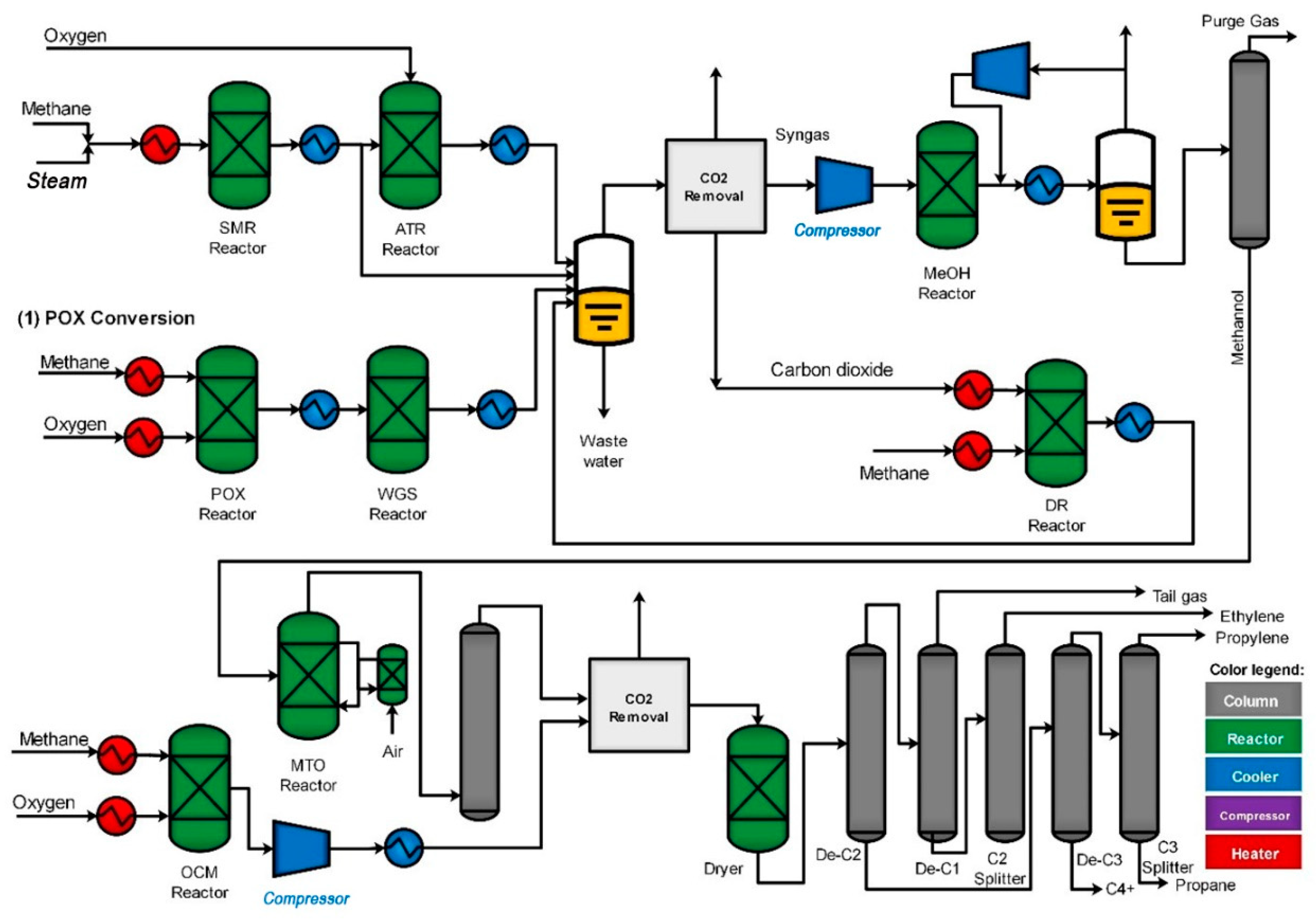
Figure 1. Methane-to-olefins flowsheet using SMR, DRM, and POX reforming technologies.
Hydrogen 03 00001 g001
Figure 2. The effect of CH4:H2O ratio on conversion, syngas yield, CO2 and H2O generation, energy input, and carbon deposition in SR (p = 1 bar). (a) impact of varying the temperature with different CH4:H2O ratios on H2 production, (b) impact of changing the temperature with different CH4:H2O ratios on CO production, (c) impact of varying temperature on carbon balance at CH4:H2O = 1:1, (d) impact of changing temperature on carbon balance at CH4:H2O = 1:10, (e) simple block diagram of SMR.
Hydrogen 03 00001 g002
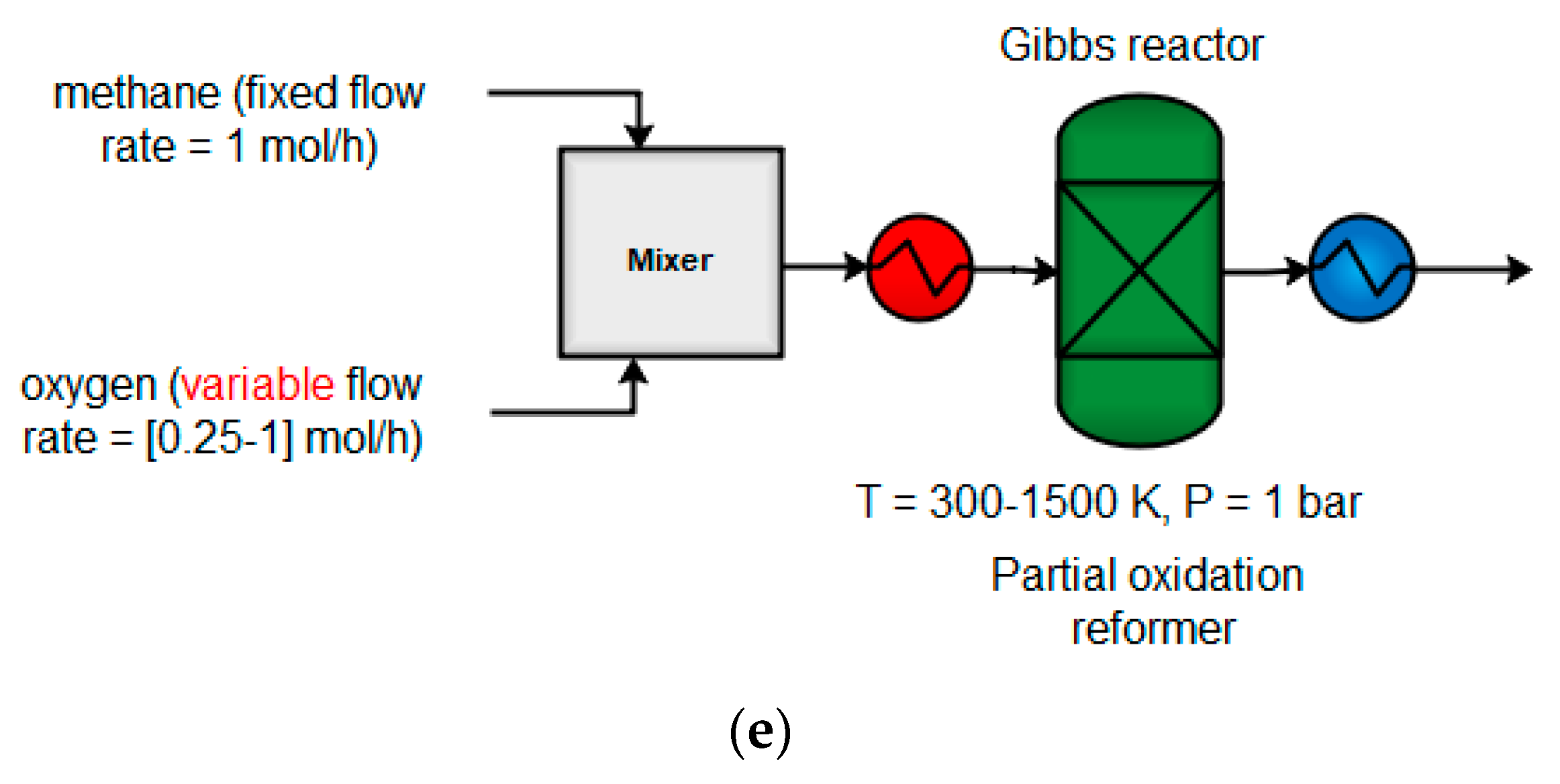
Figure 3. The effects of CH4:O2 ratio on conversion, syngas yield waste production, energy input, and carbon deposition in POX (p = 1 bar). (a) impact of varying the temperature with different CH4:O2 ratios on H2 production, (b) impact of changing the temperature with different CH4:O2 ratios on CO production, (c) impact of varying temperature on carbon balance at CH4:O2 = 1:0.25, (d) impact of changing temperature on carbon balance at CH4:O2 = 1:0.75, (e) simple block diagram of POX.
Hydrogen 03 00001 g003aHydrogen 03 00001 g003b
Figure 4. The effects of CH4:CO2 ratio on conversion, syngas yield, CO2 generation, and carbon deposition in DR (p = 1 bar). (a) impact of varying the temperature with different CH4:CO2 ratios on H2 production, (b) impact of changing the temperature with different CH4:CO2 ratios on CO production, (c) impact of varying temperature on carbon balance at CH4:CO2 = 1:1, (d) impact of changing temperature on carbon balance at CH4:O2 = 1:5, (e) simple block diagram of DR.
Hydrogen 03 00001 g004
Figure 5. The effects of CH4:O2 ratio on conversion, syngas yield waste production, energy input, and carbon deposition in ATR (p = 1 bar). (a) impact of varying H2O or O2 on H2 production, (b) impact of varying H2O or O2 on CO production, (c) impact of varying H2O or O2 on CO2 production, (d) impact of varying H2O or O2 on reformer energy, (e) simple block diagram of ATR.
Hydrogen 03 00001 g005aHydrogen 03 00001 g005b
Figure 6. The effects of CH4:O2 ratio on conversion, syngas yield, energy input, and carbon deposition in CR (p = 1 bar). (a) combination of SMR and DRM, (b) combination of POX, SMR, and DRM, (c) impact of varying temperature on carbon balance using SMR and DRM, (d) effect of changing temperature on carbon balance using POX, SMR, and DRM, (e) simple block diagram of CR.
Hydrogen 03 00001 g006aHydrogen 03 00001 g006b
Figure 7. (a) The effects of varying the CO:CO2 ratio with fixed H2 (nH2 = 2 mol) feed on the conversion of syngas to produce methanol at 373 K and 10 bar; (b) the effect of varying both CO and H2 in the reactor feed without CO2 as a co-feed, at 373 K and 10 bar; (c) the same outlet composition obtained from the CR was used as a feed for the methanol reactor.
Hydrogen 03 00001 g007
Figure 8. The energy input for syngas production from various routes: (a) DRM, (b) SMR, (c) (POX), and (d) (CR).
Hydrogen 03 00001 g008
Figure 9. The energy input for ethane steam cracking process.
Hydrogen 03 00001 g009
Figure 10. The proposed methane to olefin design-process flow sheet.
Hydrogen 03 00001 g010
Figure 11. The temperature−enthalpy change diagram for: (a) the baseline; (b) the integrated approach; and (c) the grand composite curve for heat integration of the methane-to-olefin plant.
Hydrogen 03 00001 g011
Figure 12. The heat exchanger network (HEN) diagram obtained with the ASPEN Energy Analyzer, where red lines show hot streams, and blue lines show cold streams for: (a) the baseline, and (b) the proposed heat integration network.
Hydrogen 03 00001 g012aHydrogen 03 00001 g012b
Figure 13. The effect of energy integration on heating and cooling requirements and carbon emissions. (a) actual total and heating utilities compared to the recommended target, (b) actual cooling utilities and carbon emissions for the conventional process configuration compared to the recommended design target.
Hydrogen 03 00001 g013
Table 1. Product distribution for the MTO reaction [8,45].
Yield (%)Yield on C Basis (%)
Ethylene 21.549.0
Propylene14.032.0
Butene4.3010.0
Methane 0.932.18
Ethane 0.180.42
Pentane 0.952.00
Hydrogen0.380.90
Coke1.333.00
CO20.210.50
Water56.2-
Table 2. Cost parameters for the economic evaluation of the process.
ItemBest Value (USD)
Shale gas5.6/MMbtu
Ethane 0.50/gal
Ethylene 1200/ton
Propane 1.00/ga
Butene 1.60/ga
Hydrogen 1.76/kg
Propylene 1340/ton
Electricity 0.07/kwh
Table 3. Process utilities and feedstock prices.
Methane purchase price (USD kscf−1) [60]3.5
Grade 1 refrigerant2.74 × 10−6
Cooling water (USD kg−1) a3.08 × 10−5
Steam, 100 PSI (USD kg−1) a0.0179
Fired heater, 1273 K (USD kJ−1) a4.2 × 10−6
Electricity (USD kg−1) a0.0775
a Estimated via the Aspen Process Economic Analyzer.
Table 4. The total capital and operating costs for the methane-to-olefin plant.
Total Capital Cost (USD MM)17.54
Total Operating Cost (USD MM/Year)55.31
Total Raw Materials Cost (USD MM/Year)7.23
Total Utility Cost (USD MM/Year)4.92
Desired Rate of Return (Percent/Year)20
Equipment Cost (USD MM)6.76
Total Installed Cost (USD MM)9.50
Table 5. Heat load for methane-to-olefin design process flow sheet.
EquipmentHeat LoadUnit
COMPR522.2kWh
COMPRESS5968
OXIHETR12.22MMBtu
CH4HETR7.29
RECYHTR0.11
C3H6H4.00
HEATER19.56
SYNCOOL15.81
C2H4H6.10
C4H8H1.01
CHILLER14.36
Table 6. The impact of heat integration for the methane-to-olefin plant.
Current
(kJ/s)
Target
(kJ/s)
Saving Potential
(kJ/s)
Energy Cost Savings
(USD/Yr)
Energy Cost Savings
(%)
ΔTmin
(K)
LP Steam444204442266,340100.0010.0
Fired Heater5752153.45599750,92297.3325.0
Total Hot Utilities1.02 × 104153.41.00 × 1041,017,26398.02-
Cooling Water41551.22 × 104−8043−53,808−193.565.0
Refrigerant 1.99 × 10429.871.99 × 1041,724,93099.853.0
Total Cold Utilities2.41 × 1041.22 × 1041.19 × 1041,671,12295.20-
Publisher’s Note: MDPI stays neutral with regard to jurisdictional claims in published maps and institutional affiliations.