1. Introduction
Cell towers are critical telecommunications infrastructure facilities. They ensure the stability and quality of communication, access to the internet, and the speed of information transmission, which is especially important in remote regions or during emergencies [
1,
2,
3]. At the same time, cellular towers are highly loaded structures that must be guaranteed to withstand a wide range of static and dynamic loads, including wind, snow and ice loads, etc. [
4,
5,
6]. Therefore, during design and assessment calculations for strength, stiffness and stability, it is necessary to take into account all the significant factors affecting the operational reliability of these structures. This is especially true for mountainous regions, where structures face unique challenges, such as high wind and snow activity, difficulties in accessing the location, and sometimes limited space for the foundation [
7,
8,
9,
10]. Today, an additional factor complicating the operation of towers in mountainous regions is climate change [
11,
12,
13,
14]. Many regions of the world, including the Ukrainian Carpathians, experience abnormal climatic phenomena that provoke unfavourable physical and geographical processes, such as hurricanes, heavy rains, flooding, sudden temperature changes, etc. Considering such changes during design is important to ensure reliable and safe operation of the telecommunications infrastructure. Moreover, the ongoing military operations in Ukraine create additional challenges for the operation of cell towers [
15,
16]. Damage to infrastructure due to hostilities requires a rapid response to restore communications, which is vital in times of crisis.
Traditionally, metal towers for cellular equipment are divided into several main types depending on their design features and application. Masts are high-rise structures consisting of a single pipe or a built-up structure, which are fixed with guy lines [
17,
18]. They are cost-effective, but require a large area for fastening and periodic monitoring of the condition of the guy lines and their tension. Lattice towers are mostly triangular or rectangular structures made of metal profiles that provide high stability and allow equipment to be placed at different levels [
19,
20]. Monopole towers are steel columns without guy lines, with a simple design and quick installation [
21,
22]. Combined structures combine elements of lattice and monopole towers, allowing for adaptation to specific operating conditions [
23]. Each type has its own advantages and disadvantages that need to be taken into account during the design process, depending on the operating conditions, including climatic, geographical and economic restrictions.
Cell towers intended for remote mountainous regions must balance compactness, structural reliability, and ease of installation under constrained foundation conditions. Three common tower types are considered for such environments: guyed masts, metal monopoles, and lattice towers (
Figure 1). Among them, square lattice towers offer the best trade-off between strength, durability, and load capacity, making them the most suitable solution when foundation area is limited and environmental conditions are severe.
The design of metal towers is based on three main approaches. Analytical methods allow obtaining mathematical solutions to determine the stress–strain state of structures [
24,
25]. They are effective for preliminary calculations and optimisation of the main parameters of structures. Numerical methods, in particular the finite element method, are used to model complex structures and take into account the effects of combined loads [
26]. The use of software packages, such as SCAD, allows for a detailed analysis of the behaviour of structures under various scenarios [
27,
28]. Experimental studies include testing of samples and prototypes of towers to assess the real behaviour of structures [
29,
30]. They provide a high level of accuracy but require significant financial and time resources.
Current studies aimed at developing new approaches and structural solutions to improve the efficiency of metal structures and facilities are presented in [
31,
32,
33]. A promising direction is the introduction of lightweight high-strength materials, in particular aluminium and composite alloys, which reduces the weight of structures while maintaining their load-bearing capacity [
34,
35]. An important role is also played by the use of specialised protective coatings that extend the life cycle of structures and ensure their stability in aggressive environments [
36,
37,
38]. An effective solution is the use of modular systems that simplify the transport and installation of towers in remote or hard-to-reach regions [
39]. In the context of energy efficiency, solar panels and wind energy systems are being integrated to provide autonomous power to equipment located on towers [
40]. The use of intelligent monitoring systems, in particular smart controllers capable of tracking the dynamic operation of metal structures in real time, is of considerable interest [
41,
42]. Particular attention is paid to improving methods of diagnostics and calculation of long-term structures, taking into account the gradual degradation of mechanical properties of materials and the impact of stress concentrators [
43,
44], as well as the development of defects [
45,
46,
47] and cracks [
48,
49,
50]. In order to reduce dynamic loads caused by wind flows and seismic impacts, researchers propose the use of inertial and frictional dampers and other types of vibration dampers [
51,
52,
53,
54]. Thus, the modern design of telecommunication towers combines innovative materials, monitoring and vibration protection technologies, and calculation methods to ensure reliability in difficult conditions [
55,
56].
Optimization of lattice telecommunication towers operates on three interlocking levels. First, geometric proportioning—plan form (triangular or square), leg inclinations, panel heights, and the location of the pyramidal-to-prismatic interface—governs global stiffness, steel mass, and natural frequencies; studies on topology and proportioning for towers and related lattice masts consistently show that judicious placement of the transition and rational panelization improve the stiffness–weight balance [
57,
58,
59,
60]. Second, configuration design covers three choices: the bracing scheme (X, K, or diamond), the grouping of members, and the cross-section family (angles or tubes). It works best when treated as a combined size, shape, and topology problem.
The design must satisfy standard limits on strength, drift, stability, and modal separation.
Modern metaheuristic methods—genetic algorithms and simulated annealing—explore these coupled discrete–continuous spaces effectively. They are often paired with surrogate models and have proven reliable [
59,
60,
61,
62,
63]. Third, detailing and constructability—joint design, splice locations, tolerances, transport modules, and the interface with compact foundations—should be embedded as hard or penalized constraints so that mathematically optimal solutions remain buildable in constrained mountainous terrain [
58,
60,
61,
62]. Taken together, this systems view aligns advances in structural optimization with field realities and explains why simple, testable design rules for the transition height can emerge as robust, practitioner-friendly outcomes [
57,
58,
59,
62].
This study was prompted by a real industrial problem. In recent years, several cell tower accidents have occurred in the Carpathian region, causing serious concern among telecoms operators, construction companies and regulators. Previously, similar tower designs had worked flawlessly, but now their operation has faced new, unforeseen problems. Inspection of damaged towers and technical expertise of those in pre-emergency condition revealed two key factors that significantly affected their load-bearing capacity.
The first factor is the limited area available for foundation placement. Many towers were built in mountainous terrain where flat areas are extremely limited and geological conditions make large-scale excavation difficult. The high steepness of the slopes, the risk of landslides, the heterogeneity of the soil and the presence of rock often made traditional methods of laying foundations with a large base area impossible. In addition, the need to transport construction materials to hard-to-reach areas forced engineers to optimise the weight and size of foundation structures. As a result, compromise design decisions were often made to reduce the base area.
The second factor is force impacts that exceed normal values. Abnormal climatic events, such as hurricane force winds, heavy snowfall, flooding, or sharp temperature fluctuations, have created loads that exceed those considered in existing regulations when designing towers [
64,
65,
66,
67,
68]. This is especially true for remote mountainous regions where weather conditions are rapidly changing and often unpredictable. In addition, the analysis showed that existing directives and regulations in some cases do not take into account the latest trends related to climate change and the growth of anthropogenic pressure. In particular, the basic norms used to calculate loads were created decades ago and do not take into account new extreme conditions.
The aim of this study is to develop practical design guidance for lattice cell towers erected on compact foundations in mountainous terrain, taking into account code-based wind and icing load combinations. Particular emphasis is placed on the influence of the pyramidal–prismatic transition height on structural stiffness, material efficiency, and modal adequacy. This research consolidates effective technical solutions and supports safer, more reliable network operation in hard-to-access regions through a concise, reproducible design workflow.
To conclude the introduction, a few words should be said about the structure of this article. In the following section, Materials and Methods, we immediately present and analyze the finite element models of two tower variants—one using tubular elements and the other using angle sections—both featuring the transition from the pyramidal to the prismatic part of the shaft at the optimal height. Although this optimized configuration is the outcome of later analysis, it is introduced early in the article to clearly demonstrate the modelling methodology, boundary conditions, and load scenarios. The subsequent section (Results and Analysis) examines the deformation behaviour, internal forces, and material consumption of these optimized towers under combined loading. After this, in the final sections, we present the rationale and the process by which the optimal geometry was determined.
2. Materials and Methods
We study 42 m lattice cell towers on compact foundations in mountainous terrain, comparing tubular and angle schemes under identical geometry and code-based wind and icing loads. The pyramidal–prismatic transition height is treated as a controllable geometric parameter that governs the balance between top-displacement control, steel tonnage, and modal adequacy.
2.1. Numerical Models of Lattice Towers
Numerical modelling of cell towers is an important stage in the design, analysis of their load-bearing capacity and operational behaviour. Let us consider the creation of a spatial computational model of a quadrilateral lattice tower in the SCAD Office 23.1.1.1 software package (a computational complex for strength analysis of structures using the finite element method).
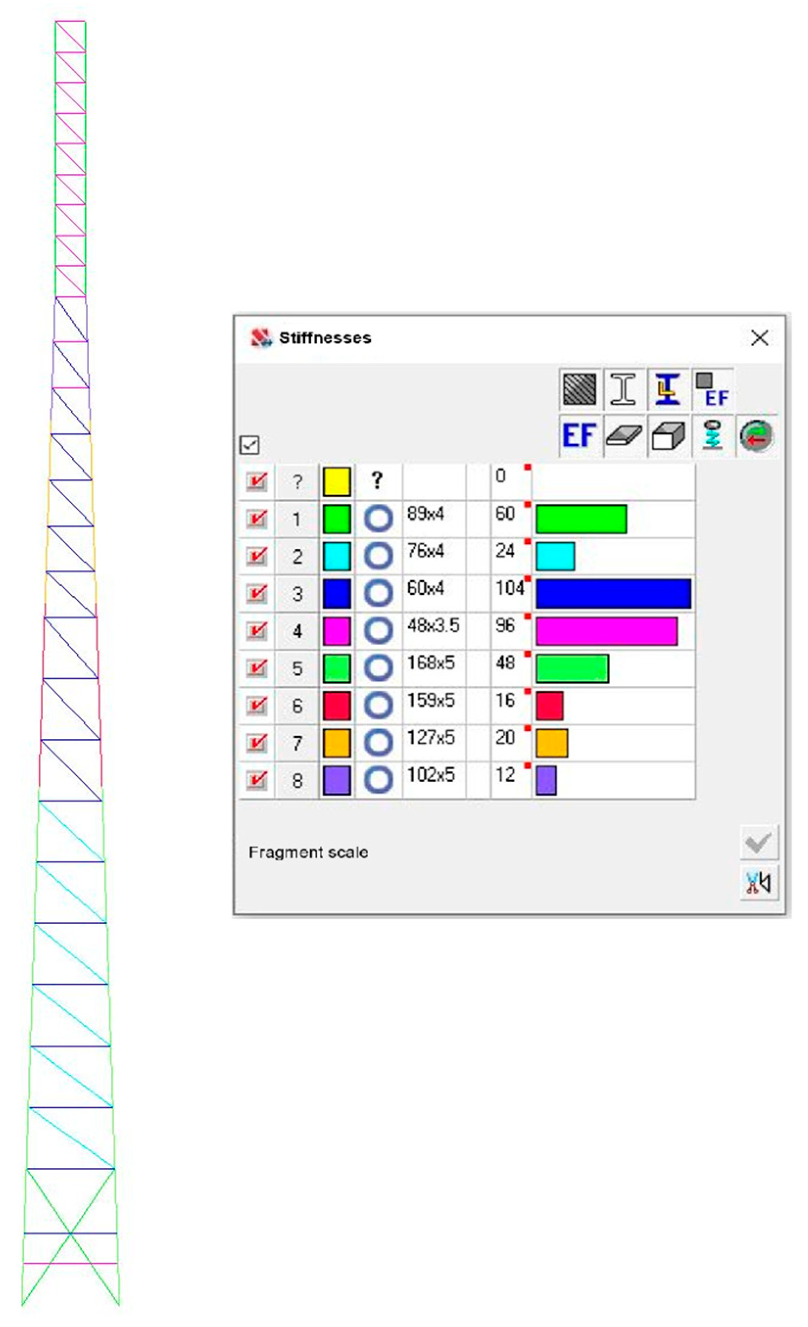
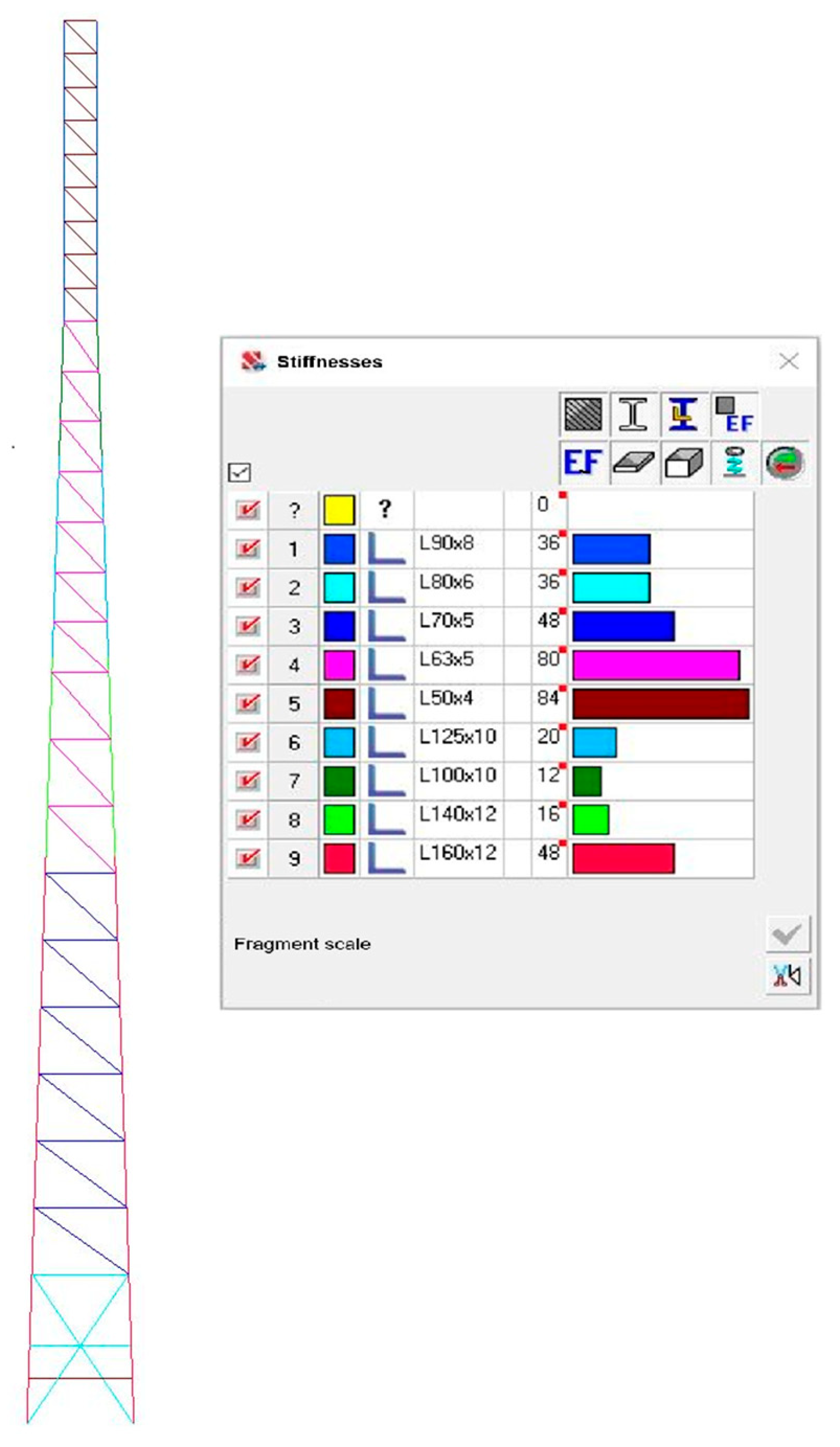
The overall geometrical parameters of the tower are: total height—42 m; base dimensions—3.2 × 3.2 m, which corresponds to the conditions of the limited base area. The tower body is pyramidal from 0.000 m to 33.000 m, prismatic from 33.000 m to 42.000 m, and the upper base is 1.0 m × 1.0 m (see
Figure 2 and
Figure 3).
S235 steel with the following physical and mechanical characteristics was selected as the main material for structural modelling: elastic modulus—
; Poisson’s ratio—0.3; bulk weight—7850 kg/m3; linear expansion coefficient—
1/K, characteristic yield strength—235 MPa, characteristic tensile strength—360 MPa.
When evaluating the choice of modelling method, we found that the use of solid modelling to analyse the lattice structure of the tower was excessively resource-intensive both in terms of computing power and due to the increased complexity of the results’ pre-processing and interpretation. Instead, the choice of rod finite elements made it possible to significantly reduce the amount of computation while maintaining the accuracy of determining the stress–strain state of the structure. In addition, this methodology corresponds to the actual physical behaviour of the tower elements, which work mainly in tension and compression.
Therefore, spatial rod finite elements with six degrees of freedom at each node were used for modelling: three linear displacements (X, Y, Z) and three angular displacements (Ux, Uy, Uz). This approach makes it possible to correctly convey the main forces that occur in the nodes of the structure. In addition to the global coordinate system, each rod element has a local right-handed Cartesian reference system, relative to which forces are determined and local loads can be set. During the calculation, the stiffness matrix is built for the entire elastic part of the rod element, and at least five design sections are considered for each finite element, which guarantees an accurate assessment of the distribution of internal force factors along its length.
All lattice elements are connected to each other and to the chords by means of hinged joints, which corresponds to the actual operating conditions of the tower structure and allows for an accurate reproduction of its behaviour under load. The numerical model contains 148 nodes, which ensures an adequate representation of the nodal connections and makes it possible to analyse the stress–strain state of individual structural elements. The total number of finite elements is 380, which corresponds to the selected lattice tower design. The methodology used to create the numerical model allows obtaining correct results for analysing the strength and stability of the structure.
For the purpose of comparative analysis, two numerical models describing the spatial lattice structures of the towers were created. The main difference between the models is the use of different shapes of cross-sections of structural elements:
- -
Model 1 (
Figure 2)—All rod elements are made of round tubes.
- -
Model 2 (
Figure 3)—All rod elements are made of equilateral angles.
The choice of these profiles is explained by their wide availability in the Ukrainian construction materials market and the technological features of their use during installation.
Figure 2 and
Figure 3 show the design diagrams of numerical models of the towers, where the stiffnesses of individual rod elements are indicated by colour coding. This colour indication allows for quick identification of structural sections with increased or decreased stiffness, which is important for analysing the stress–strain state of the structure and optimising its performance.
2.2. Boundary Conditions and Load Scenarios
The metal tower is structurally designed as a spatial rod system consisting of a vertical lattice body clamped to the base. The upper components of the tower are left free to ensure the distribution of climatic and dynamic loads.
The calculations and analysis of the operational performance of the towers take into account the impact of permanent and temporary loads, as well as their critical combinations.
Constant loads: the dead weight of metal structures, determined taking into account the coefficient of 1.05 directly in the calculation complex; weight of technological equipment, detailed data on which are given in
Table 1.
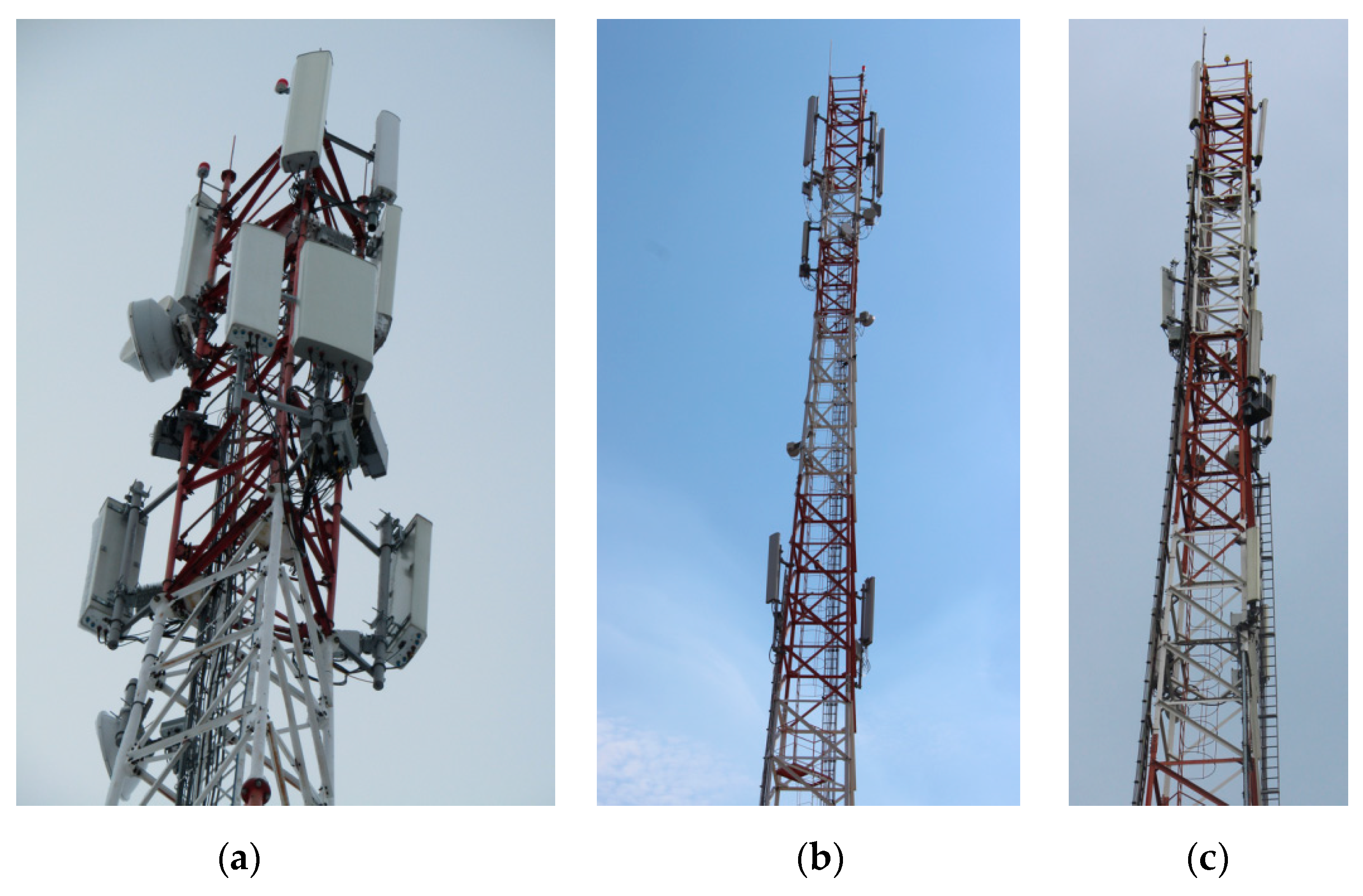
Figure 4 shows a general view of typical technological equipment: antenna systems, radio units, feeders, etc. Attention should be paid to the location of the equipment along the height of the tower, taking into account the rational distribution of masses and wind area. Antennas are usually mounted at the top to improve signal coverage, while power supplies, switch cabinets and other auxiliary equipment can be placed at the bottom.
In total, the towers we are looking at have nine panel antennas installed, providing sectoral network coverage in the 700–2600 MHz range. To support their operation, eighteen radio modules are used to amplify and modulate the signal directly near the antennas, minimising feeder losses and increasing network efficiency. Four radio relay antennas operating in the microwave range are installed to provide backhaul communication between the base stations. Signal transmission between the components is carried out via coaxial feeders, and power is supplied to the active equipment via 22 power cables. For synchronisation and high-speed data transmission, 22 optical cables are used to connect the antenna modules, the base station and the network core.
Temporary loads: wind and ice loads determined in accordance with the regulatory requirements for the 4th wind region and the 2nd type of terrain at an altitude of 750 m above sea level (using a correction factor that takes into account the increase in the intensity of wind loads with increasing altitude); wind pressure fluctuation, which takes into account the dynamic component of wind impact.
Figure 5 and
Figure 6 show the vertical scans of the towers with section numbering, height marks and the scheme of wind loads applied to the chords. A detailed comparison of the wind loads at different tower heights and information on the cross-sections of the elements at these heights is given in
Table 2. To quantify the dynamic behaviour of the tower, static loads were converted into masses and the natural modes and frequencies were determined using the Lanczos method in the frequency range from 0 to 3.8 Hz, with the first natural modes taken into account. This approach makes it possible to detect possible resonance phenomena and adequately assess the impact of the wind pulsation component.
For each scenario, as well as for dangerous load combinations, simulation modelling was carried out to determine deformations and stresses in critical areas of structures and to assess strength, stiffness and stability by limit states. The analysis of the main results is presented in the next section of the paper.
To summarise the climatic actions and their traceability, we define the site as wind region IV with terrain category II and an elevation of about 750 m, derive the basic wind pressure with height and exposure adjustments, and apply gust and pressure coefficients appropriate to lattice towers and appurtenances. The resulting pressures are distributed by tier to chords and bracing as line loads following the wind-application scheme in
Figure 5 and
Figure 6, while antenna, microwave and cable systems are represented through their drag areas and masses from
Table 1. For winter conditions, ice accretion thickness and density are taken in accordance with DBN V.1.2-2:2006 “Loads and Actions,” combined with concurrent wind to form the governing design cases, including storm wind without ice, winter wind with ice, and construction-stage wind. Static actions and self-weight are converted to consistent nodal masses for modal analysis, with mode shapes and frequencies evaluated in the 0–3.8 Hz range. Global shears and overturning moments are cross-checked against hand estimates to confirm load-path fidelity, and identical partial factors and boundary conditions are maintained across alternatives to ensure transparent comparability. For alignment with international practice, an equivalent workflow may be carried out using EN 1991-1-4 and ISO 4354 for wind, ISO 12494 for atmospheric icing, ANSI/TIA-222-I for telecom appurtenances and load categories, and EN 1993-3-1 for global analysis and member checks [
69,
70,
71,
72,
73].
3. Results and Analysis
3.1. Analysis of the Deformed State of the Towers
The towers were calculated for the 4th wind region, terrain type 2, taking into account the geographical height of 750 m and a correction factor that specifies the value of dynamic wind pressure (the current State Construction Norms B.1.2-2:2006 ‘Loads and Impacts’ was used as a regulatory basis). The applied calculation approaches do not contradict the current State Construction Norms B.2.6-198:2014 “Steel structures. Design standards”. The design life of the facility is 40 years. The liability reliability factor was adopted in accordance with State Construction Norms B.1.2-14:2018 ‘System of ensuring reliability and safety of construction facilities’. The towers are designed for the installation of amplified power antenna and feeder equipment with a total area of 9 m2 in the upper part of the tower.
Note that, for international consistency, wind actions and exposure can be modelled in accordance with EN 1991-1-4 and ISO 4354, atmospheric icing with ISO 12494, telecom appurtenances and importance categories with ANSI/TIA-222-I, and the global analysis and member verification with EN 1993-3-1 [
69,
70,
71,
72,
73].
The analysis of the deformed state of the tower was carried out taking into account the most unfavourable combination of loads: the structure’s own weight, the weight of the technological equipment (antenna and feeder systems with a total area of 9 m2 located in the upper part of the tower), as well as the ultimate wind load acting on both the structural elements of the tower and the installed technological equipment. Simulation modelling was used to determine the deformations and displacements of the structure, including both static and dynamic analysis, including the effect of the pulsation component of the wind load. The calculations were performed in the SCAD Office 23.1.1.1 software package.
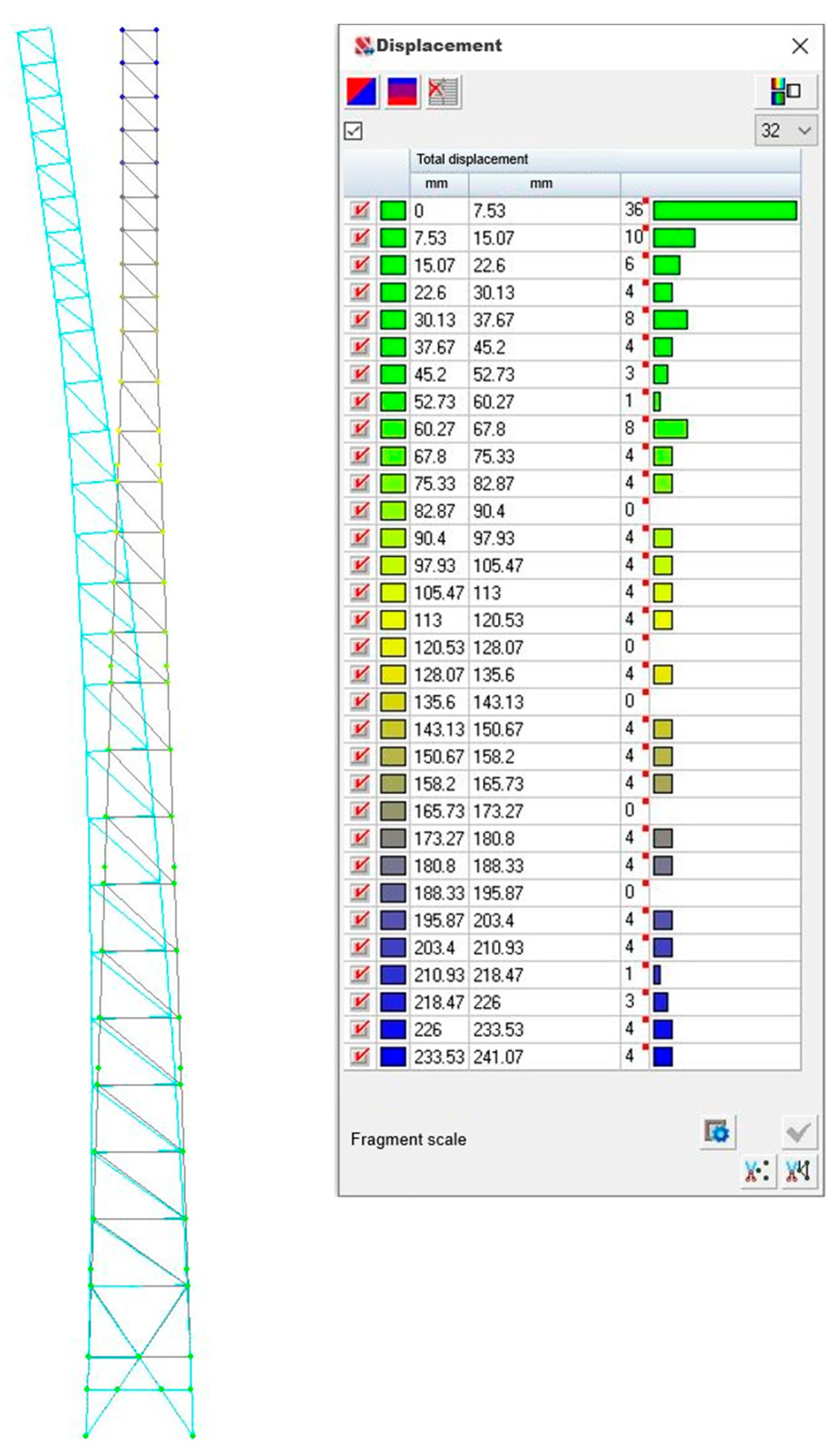
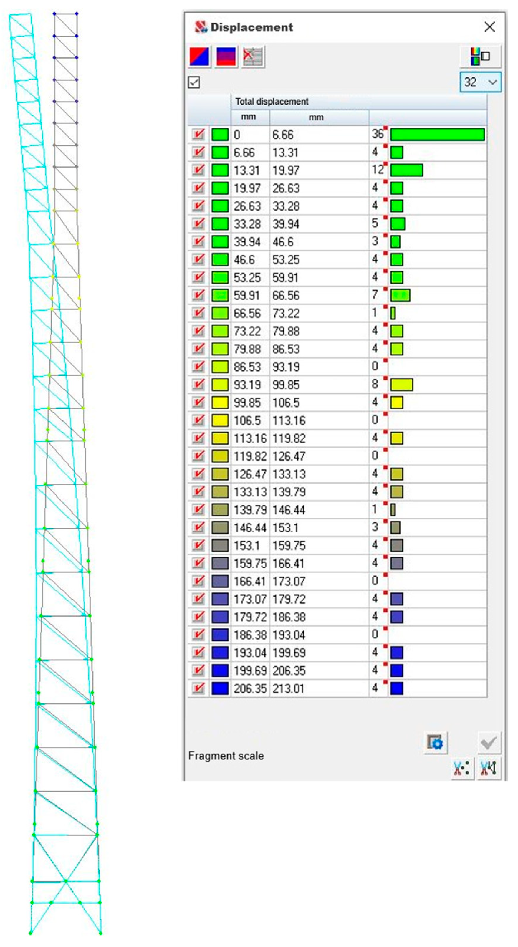
The modelling results indicate that the deformability of the structure is largely determined by the type of cross-section of the elements used. The towers made of tubular elements show greater horizontal displacements than those made of equilateral angles. The forms of displacements of the towers obtained from the results of numerical modelling are shown in
Figure 7 and
Figure 8. They illustrate the nature of deformation changes in the structure in response to static loads. In particular, the maximum horizontal displacements of the upper components for the tubular tower were 241 mm, while for the angle tower they were 213 mm. This difference (~12%) is explained by the higher spatial stiffness of the tower made of angle elements in the plane of the main loads and their ability to resist spatial deformation more effectively. An additional analysis of the structure’s behaviour under dynamic loads (pulsation component) confirmed the findings. In particular, the angle bars towers proved to be less prone to resonant vibrations, which is important given their operation under long-term exposure to variable loads.
3.2. Analysis of Internal Forces and Assessment of Tower Load-Bearing Capacity
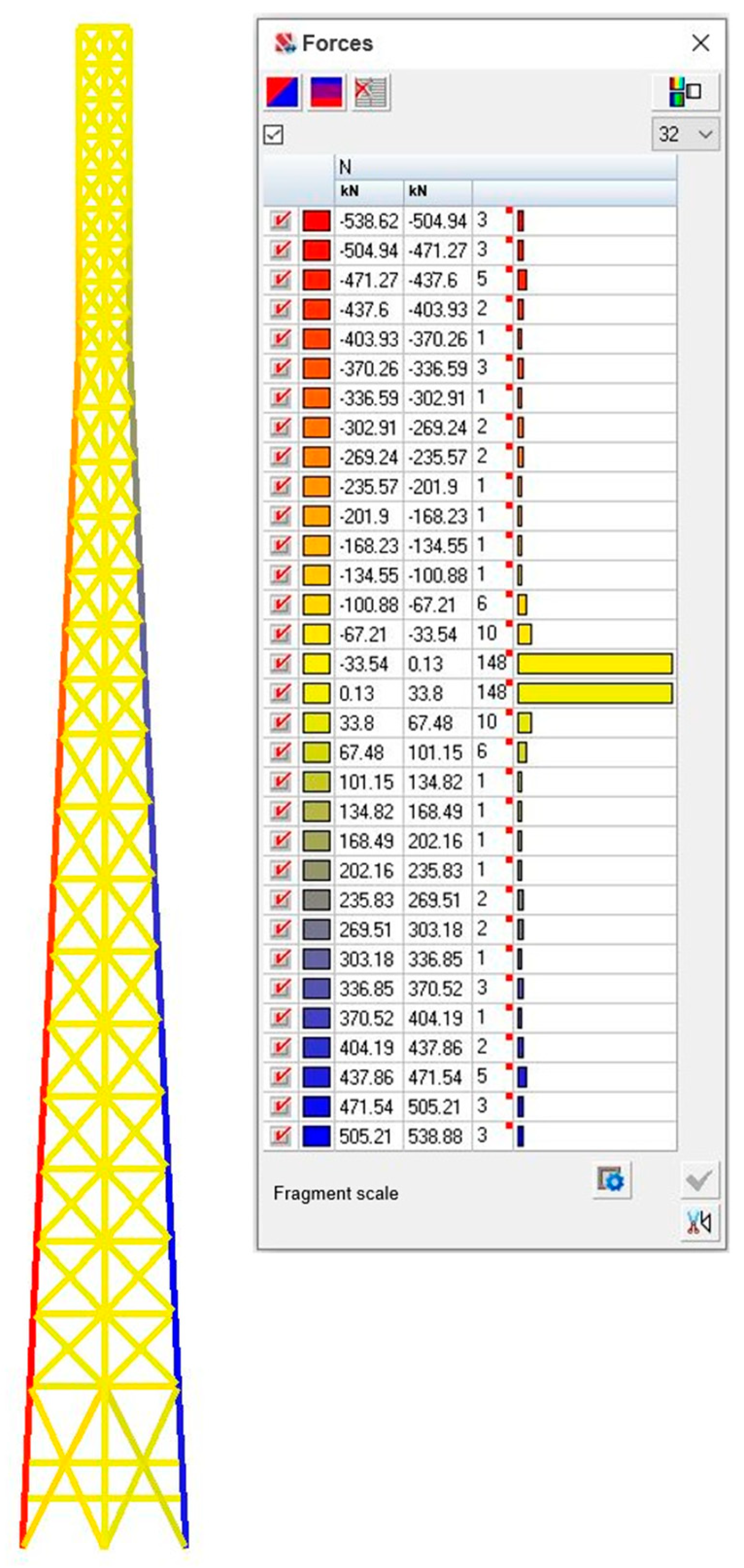
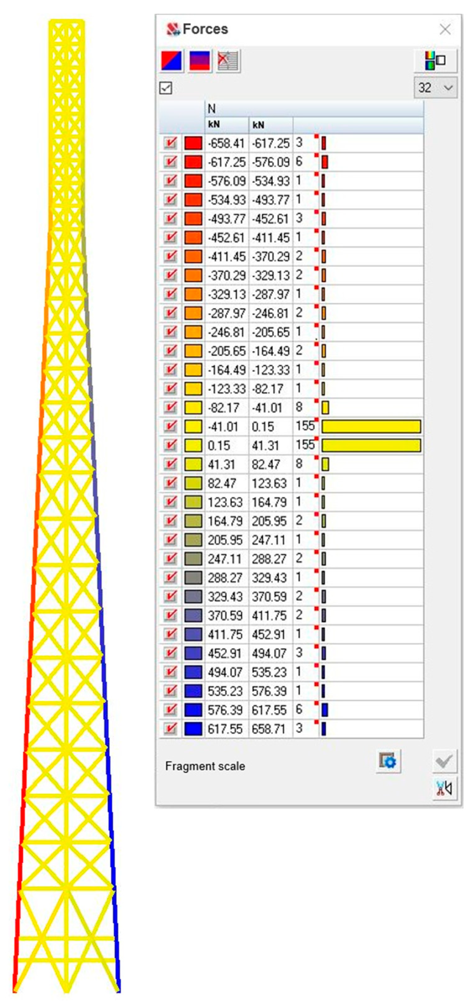
Simulation modelling was carried out to determine the internal forces in the tower’s structural elements and assess their load-bearing capacity under the most adverse loads. The simulation took into account combinations of the following loads: the tower’s own weight, the weight of technological equipment and the pulsation component of wind loads. Colour chromograms of the calculated forces are shown in
Figure 9 and
Figure 10.
The analysis of the results shows that the round tube tower demonstrates a more uniform distribution of forces in the rods. This is due to the fact that tubular sections have the same stiffness in all directions, which contributes to better force distribution through the nodes. In contrast, a tower made of equilateral angles has more pronounced force contrasts in adjacent rods. This may be due to the fact that the angle sections have different stiffnesses in the main plane of inertia and outside it, and they can also create larger eccentricities in the nodes. The absolute values of axial forces in the tower made of angular sections are higher (
Table 3). This may indicate a lower overall stiffness of the structure, resulting in a redistribution of forces between the rods. The higher compressive forces in the angle elements may mean that these elements are at greater risk of losing local or overall stability, although the current load carrying capacity checks have shown that they are in compliance. The absolute values of the forces in the tower made of angles are higher than those in the tubular tower, with a difference of 19%. In more detail, the difference in forces in the structural elements of the towers (with reference to the cross-section) can be estimated in
Table 3.
Note that for the tube tower, the assemblies perform more uniformly, as evidenced by the smooth gradient of the colour chromogram. Since the aerodynamic characteristics of the towers differ, the wind load is distributed differently (see
Figure 5 and
Figure 6). This causes certain differences in the nature of the force distribution along the tower height.
Therefore, if the priority of the design result is an even distribution of forces and lower peak force values, then a tower with round tubes is more efficient. It should be noted that in the event of horizontal loads exceeding the standard (e.g., hurricane winds or abnormal seismic effects, etc.), the tubular structure will better resist torques due to the axial symmetry of its cross-sections.
To make the scope explicit, we report the governing support reactions for the forty-two-metre tower with a base-to-height ratio of about one to thirteen. From the envelope of design combinations, the tubular alternative develops approximately 540 kN in a single leg, while the angle-section alternative reaches approximately 660 kN. These magnitudes occur both in compression and in uplift depending on wind with or without icing. Compact foundations should therefore be proportioned to provide hold-down of at least this order per leg, with compatible shear transfer and control of eccentricity, and in mountainous sites this typically points to reinforced anchor-cage blocks or rock-anchored base plates with straightforward access for inspection and retightening.
In SCAD Office, selection and verification of cross-sections are performed in two modes:
- –
Pass-through mode—For quick selection or verification of all tower elements, with visualisation of the load-bearing capacity utilisation in percentage;
- –
Local mode—For detailed analysis of a single tower element.
When selecting the cross-sectional dimensions of a round tube tower and an equilateral angle tower, we take into account the following:
- –
Tensile rods—Checked only for strength;
- –
Compressed rods—Apart from the strength calculation, they are additionally checked for overall stability and local stability.
The calculation results included:
- –
Percentage of use of the bearing capacity of each tower element under the first group of limit states (strength and overall stability);
- –
Percentage of use of the bearing capacity of the tower element under the second group of limit states (flexibility).
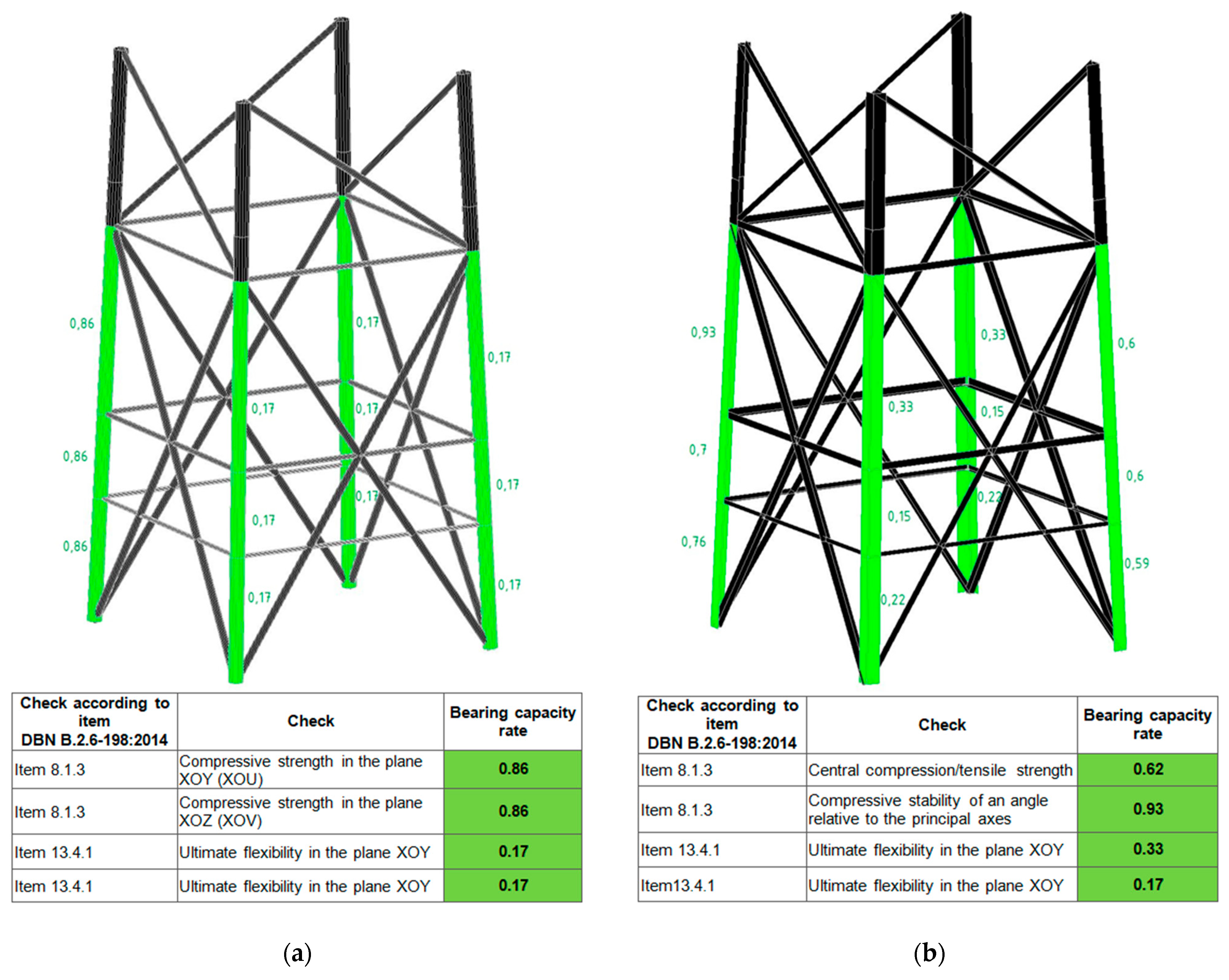
Figure 11 shows the following results for the most loaded tower sections.
All tower elements successfully passed this test. To ensure the technological efficiency of the structure, the unification of cross-sections of the elements is used, which allows the same profiles to be selected for groups of elements. An important advantage of SCAD Office is that the results obtained are automatically checked for compliance with current building regulations and standards.
3.3. Comparison of Metal Consumption
The reactions in the tower support nodes were determined using simulation modelling. The total weight of the steel structure of each tower was calculated as the sum of the vertical support reactions for the load case—‘dead weight of steel structures’. This value was obtained using the SCAD Office 23.1.1.1 calculation software with a safety factor of 1.05.
The analysis of the data showed that the weight of the main elements of the tower made of round tubes is 5630 kg, while the weight of a similar structure made of equilateral angles reaches 6420 kg. The difference in metal consumption between these options is about 14%.
Given these results, it can be concluded that the lattice tower with tubular elements has a lower metal consumption, which directly affects the reduction in the cost of materials and the overall cost of manufacturing the structure.
3.4. Optimization of the Transition Zone Location from the Pyramidal to the Prismatic Section of the Tower
The geometric configuration of a lattice tower significantly affects its overall stiffness, deformation behavior, material consumption, and resistance to operational loads. This section focuses on the analysis of one important yet insufficiently explored parameter—the position of the transition zone between the pyramidal and prismatic parts of the tower shaft. Based on engineering intuition, it was hypothesized that even a minor change in the location of this zone could affect stiffness distribution and structural efficiency. Despite its clear practical relevance, the influence of the transition zone’s location remains underrepresented in the current technical literature. Therefore, before making a final design decision, a numerical study was conducted to evaluate how variations in this geometric parameter affect key structural characteristics—stiffness, efficiency, and material use.
Five geometric configurations of the tower were considered, all sharing identical basic parameters: total height, base dimensions, top platform size, types of cross-sections of elements, and load combinations. The only variable parameter was the distance from the base of the tower to the boundary between the pyramidal and prismatic parts of the shaft. For each of the five variants, a separate three-dimensional FEM model was developed in the SCAD Office 23.1.1.1 software environment, and numerical analysis was performed as demonstrated in the previous sections. Although the overall distribution of deformations and internal forces appeared similar in visual representations, the numerical results revealed a clear sensitivity to geometric changes. Due to the repetitive nature of the graphical content, the final results are presented in tabular form (see
Table 4), enabling a direct comparison of the efficiency of all configurations according to key performance criteria.
To keep the criterion transparent and comparable, we use the dimensional penalty
and its normalized (unit-free) form
where
is the maximum horizontal displacement at the tower top for a given transition height
,
is the total steel mass, and
is the benchmark configuration (hence
).
To reflect potential priorities between drift control and steel economy, we consider a weighted generalization with a scaling exponent
:
Here
is the weight on drift and
on mass; thus
means equal price assigned to drift and mass. With equal price and
, the weighted form reduces exactly to the product form introduced above. Because raising a positive quantity to a positive power is a monotone transformation, the value of
that minimizes
is the same as for the product form.
Finally, we refer to the “knee point” as the transition height beyond which marginal efficiency deteriorates—that is, the percent reduction in top displacement per percent increase in mass drops below unity (clear onset of diminishing returns). In our data this occurs near
, which explains the practical appeal of that configuration.
To strengthen the interpretability of the efficiency criterion and make the design choice reproducible, we complement the penalty-function view with a marginal-efficiency index (MEI) between adjacent candidate heights
and
:
where
is the maximum top displacement under the governing load combination,
—negative when drift decreases;
is the total steel weight and
(typically positive). Values
indicate efficient drift reduction per unit weight,
a balanced trade-off, and
diminishing returns. In our data, the MEI decreases from values above one at 27, 30, and 33 m to values below one beyond 33 m, quantitatively confirming the observed knee near
(33 m for
). Because MEI is ratio-based, uniform scaling of lateral actions preserves this knee location.
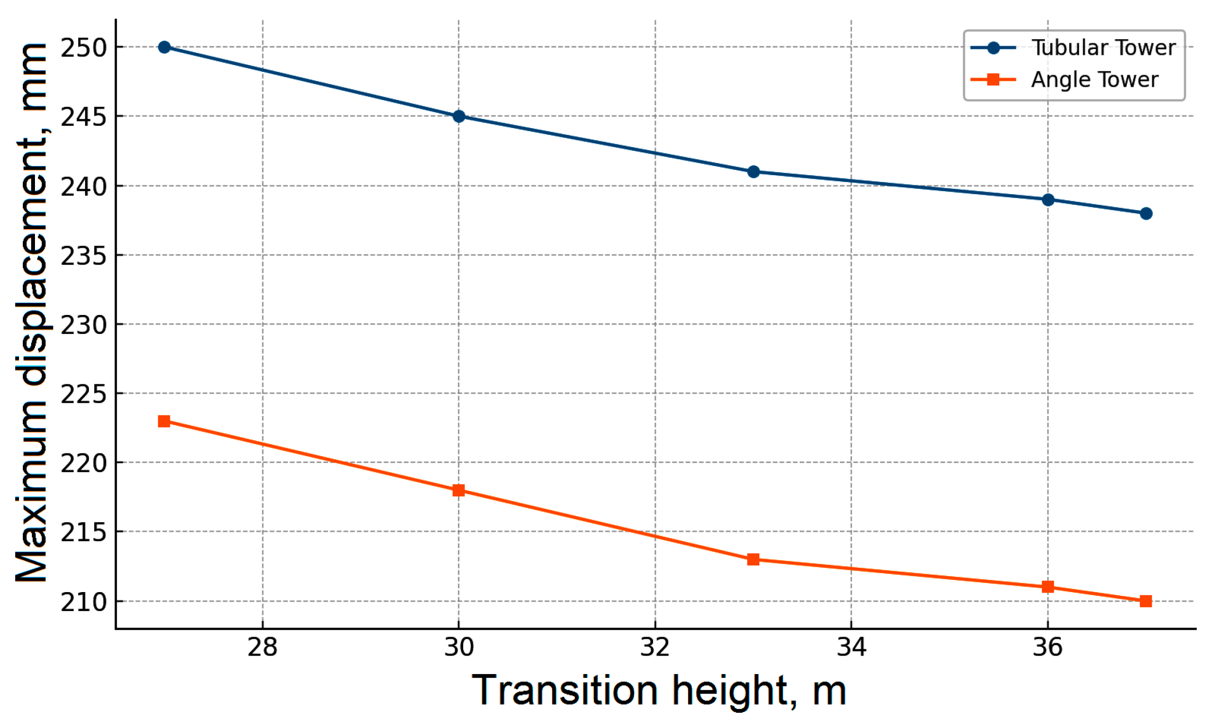
Figure 12 illustrates how the transition height affects the horizontal displacement of the tower top. The tower constructed from angle sections demonstrates better stiffness characteristics, consistently resulting in smaller displacements compared to the tubular structure. However, the analysis of how tower-top displacement varies with the transition height (
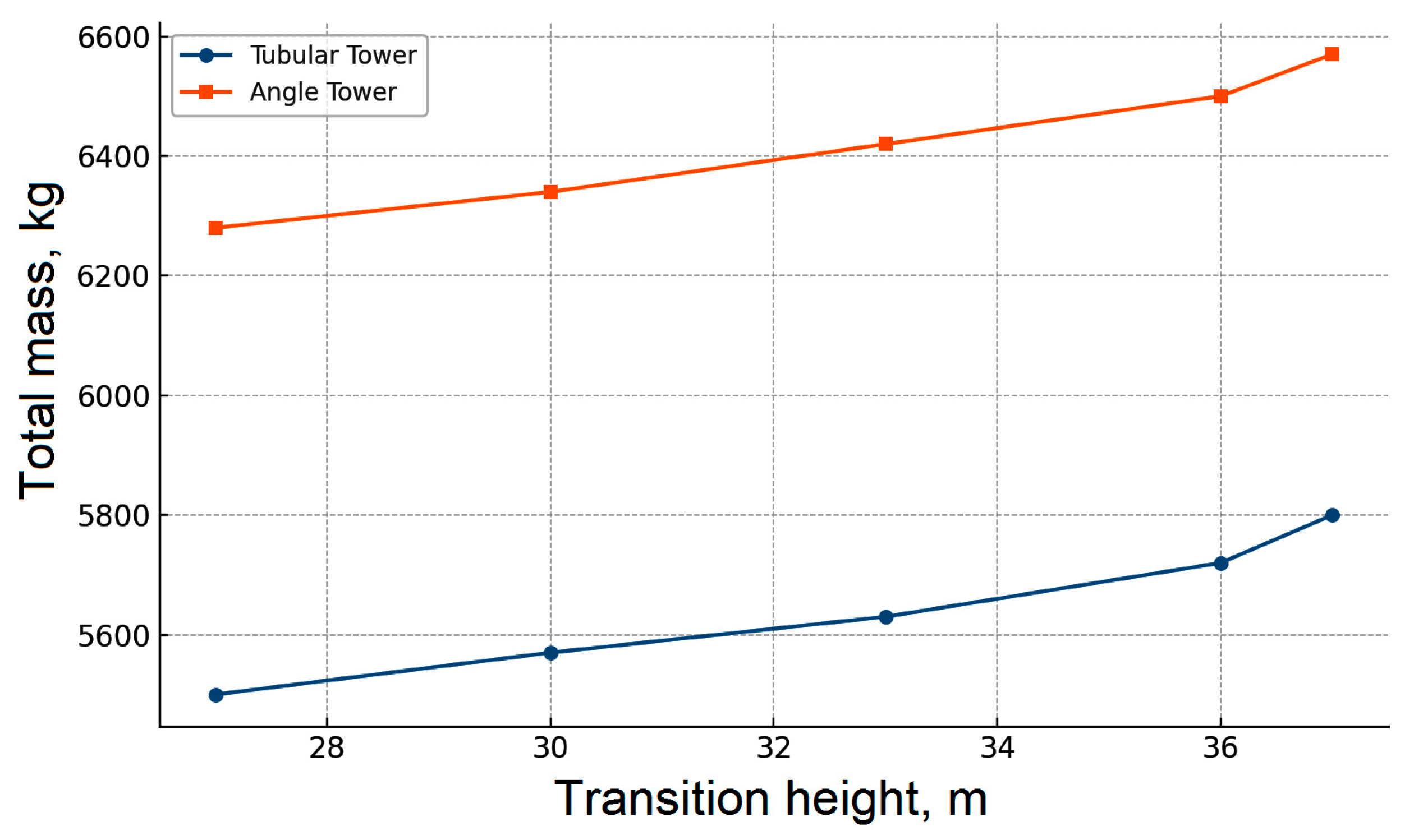
Figure 12) does not allow for an unambiguous conclusion regarding the optimal position of the transition zone. As the transition height increases, a gradual reduction in the top displacement is observed, indicating enhanced structural stiffness. At the same time, another critical parameter—the total weight of the tower—increases with a higher transition elevation (
Figure 13). Thus, a trade-off arises between two competing design objectives: minimizing displacement and minimizing material consumption.
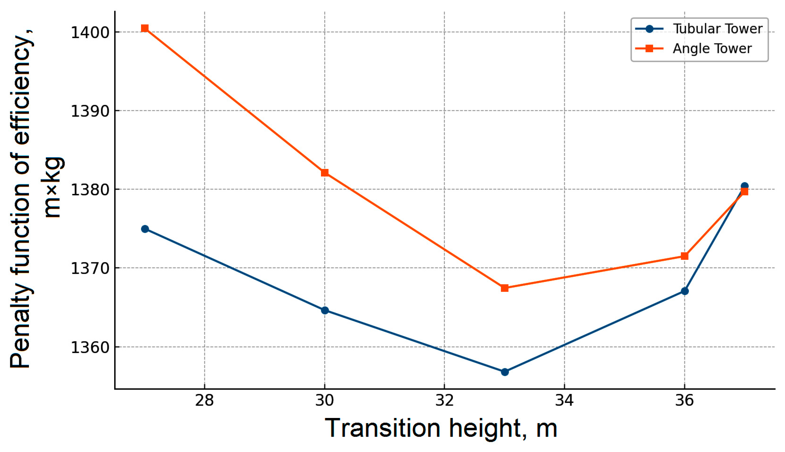
To enable a comprehensive comparison of the geometric configurations, we introduced a penalty function representing tower efficiency. This function is defined as the product of the maximum horizontal displacement at the tower top and the total structural mass. Such a generalized indicator allows for the simultaneous consideration of two key aspects: stiffness (through displacement) and material usage (through weight). The lower the value of the penalty function, the more efficient the structure is considered in terms of the engineering trade-off between deformation resistance and cost-efficiency. Physically, the penalty function reflects the “material consumption per unit of stiffness”.
Figure 14 presents the dependence of the tower efficiency penalty function on the transition height for two types of structures—tubular and angle-section towers. In both cases, the minimum of the function is observed when the transition occurs at a height of 33 m, indicating consistent behavior regardless of the cross-sectional type of the tower elements. Both models were analyzed under identical geometric and loading conditions, with the only varying parameter being the transition height between the pyramidal and prismatic parts. As shown in the graphs, the pattern of variation in the penalty function in response to changes in this parameter is similar for both tower types, which supports the structural stability and robustness of the result. It should be noted that the study examined five discrete configurations, and while the obtained optimal value of 33 m could be further refined with a more detailed gradation, any potential deviation is expected to be minor. Therefore, the transition height can be considered a significant design parameter influencing structural efficiency and should be accounted for at the early stages of tower design—especially under space-constrained foundation conditions or predefined structural weight limitations. All plots are shown in absolute SI units to preserve direct engineering interpretability, normalization is used only in the text to report relative changes and does not affect the location of the optimum.
A comparative analysis of the penalty function graphs revealed that although the angle-section tower exhibits lower horizontal displacement (i.e., greater stiffness), this advantage comes at the cost of increased structural mass. As a result, its penalty function remains higher across the entire range of examined transition heights. This outcome highlights a fundamental engineering trade-off—selecting the appropriate tower type depends on whether stiffness or structural weight is prioritized. Nevertheless, regardless of the tower type, the minimum of the penalty function is consistently achieved when the transition is placed at a height of 33 m, confirming the reliability and generality of the conclusion.
For both structural types, it was found that when the transition is located at 33 m, the most heavily loaded elements are situated in the lower tower section, with the utilization of load-bearing capacity reaching 86% for the tubular structure and 93% for the angle-section tower (see
Figure 11).
The normalized analysis shows that both section families follow the same trend relative to the configuration with the transition at 33 m—the transition height governs the stiffness–mass balance. The 33 m case is the “efficiency knee”—beyond it, additional steel yields diminishing returns in reducing top displacement, whereas below it the loss of stiffness grows faster than the mass savings. The optimum is robust, small deviations from 33 m provide no material improvement and do not change the conclusions. Recommendation—for towers on compact foundations, place the pyramidal-to-prismatic transition at approximately 78–80% of the total height (for a 42 m tower, about 33 m).
3.5. Evaluating the Efficiency of the Optimized Tower Configuration Through Modal Analysis
At the final stage of the study, a modal dynamic analysis was performed for two tower configurations—one composed of angle profiles and the other of tubular elements. The objective was to evaluate not only the static performance but also to identify potential dynamic vulnerabilities, particularly under pulsating wind loads typical of mountainous regions.
Modal analysis provides more than numerical confirmation of the first-mode frequency—it is a decisive check on the global safety margin of lattice towers. For tall and slender communication structures, even a seemingly minor shift in natural frequency can amplify wind-induced oscillations or create resonance problems. According to widely adopted standards such as Eurocode EN 1991-1-4 (Wind Actions) and ANSI/TIA-222-I (Structural Standard for Antenna Supporting Structures), the most critical range for first-mode frequencies of tall towers is approximately between 0.25 and 1.0 Hz, where the risk of overlap with dominant wind spectra is highest [
70,
71]. Ensuring that the optimized tower remains clearly above this interval confirms compliance with contemporary international practice and demonstrates that the design is robust under site-specific wind climates.
Both models were developed in SCAD Office, incorporating complete geometry and realistic loading conditions. The mass of the equipment mounted on the upper platform was modeled using concentrated dynamic masses, while the self-weight of the tower was included automatically by the software. Consequently, the computed natural frequencies reflect the response of the fully loaded structure under near-operational conditions.
The analysis revealed that the first natural frequency of the tower with angle profiles is 1.68 Hz, while the tubular tower exhibits a slightly lower frequency of 1.46 Hz. In both cases, the first and second modes share the same frequency, which can be attributed to the geometric symmetry of the towers around the vertical axis: the first two mode shapes represent orthogonal sway oscillations in the horizontal plane (see
Table 5). The third natural frequency exceeds 5 Hz in both models, ensuring a sufficient dynamic separation from higher modes.
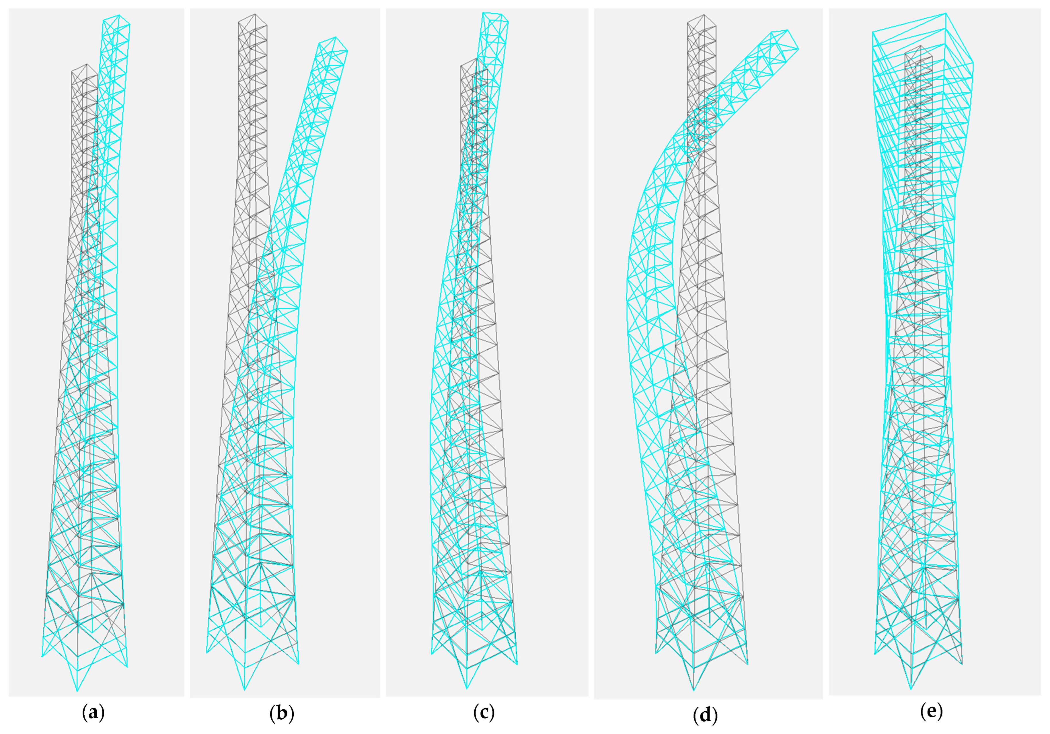
Visual inspection of the mode shapes indicated that both tower types display nearly identical vibration patterns. The dominant modes are characterized by lateral sway with increasing deformation toward the top. Since the primary geometric difference lies in the cross-section type rather than the structural scheme, we present visualizations of the mode shapes for only one model—the tower made of angle profiles (
Figure 15).
Although the computed first-mode frequencies (1.46–1.68 Hz) are relatively low, they are considered satisfactory. The relatively low first-mode frequencies are typical for tall lattice towers with slender geometries and concentrated top mass. Nevertheless, the calculated frequencies remain above the dominant energy range of the wind spectrum (0.1–1.0 Hz), reducing the risk of resonance excitation. Given the limited foundation footprint and impulsive wind characteristics typical of high-altitude sites, the selected tower configuration proves technically viable.
For winter operation, atmospheric icing increases the distributed mass of chords, bracing, and appurtenances, and this is already reflected in our load cases in accordance with the code-prescribed icing parameters for the selected climatic region. Under abnormal icing that falls outside the code envelope, the same modal check should be repeated with conservative accretion added as lumped or distributed mass to members and appurtenances. The expected effect is a downward shift of the first frequency and a corresponding increase in winter drift. For the recommended geometry the frequency margin remains adequate in typical scenarios, but if a project-specific reassessment shows a reduced margin, it can be restored by a modest upward adjustment of the transition height, by local reinforcement in the lower shaft, or by temporary operating restrictions during extreme icing events.
In conclusion, the optimized geometry—with a transition from the pyramidal to prismatic section at 33 m—ensures not only a minimum value of the static efficiency penalty function but also acceptable dynamic performance. The concurrence of optimal static and acceptable dynamic characteristics supports the recommendation of this configuration as a base model for designing communication towers under complex engineering and environmental conditions.
Apart from the structural efficiency aspects discussed above, there are also practical issues that strongly affect the choice of tower type in mountainous terrain. Tubular towers have smooth external surfaces that help shed water and ice and reduce the risk of corrosion on the outside. At the same time, their hollow interiors are vulnerable to hidden corrosion caused by condensation, which means that protection must be applied both inside and outside. This makes fabrication and long-term maintenance more complicated and expensive. Towers built from angle sections, on the other hand, are more exposed to localized corrosion at open joints and in small gaps between members. Yet their open form makes it easier to galvanize them, to spot problems during inspection, and to repair damaged areas on site. A similar contrast exists in assembly: flanged and welded joints in tubular towers demand precise fabrication and more labor, while bolted splice joints in angle towers are quicker to erect, easier to adjust, and simpler to maintain. In remote mountainous areas, where access is difficult, weather windows are short, and maintenance resources are limited, angle-section towers often prove the more practical and cost-effective solution. They may require more frequent inspection, but in return they offer simpler repair procedures and lower overall costs for protection and assembly throughout the service life.
To consolidate the engineering basis for our recommendations, we synthesize the deployment and maintainability implications of the two section families using the evidence reported above. In our models, tubular towers reduce steel tonnage by about 14 percent, which is attractive at procurement, whereas angle-section towers provide a stiffer global response and lower resonance risk within the examined height and loading regime. In mountainous terrain, field operability becomes decisive: angle towers use bolted splices and open, gusseted joints that are easy to galvanize, inspect, retighten, and repair locally. Tubular systems, though aerodynamically smooth, require both external and internal protection and rely on welded or flanged joints with tighter tolerances and more controlled assembly steps, which are difficult to assure under limited access and short weather windows at altitude. On balance, and assuming the code-based wind-with-icing combinations and the optimized transition height adopted here, this trade-off often shifts the practical choice toward angle-section towers. Transport logistics, crew productivity, and contractor means and methods remain project specific and should be confirmed at bid level. The present paper provides the structural and operational rationale on which those planning checks can build.
4. Conclusions
This paper presents a comprehensive analysis of structural solutions for the design of metal cell towers adapted for operation in remote mountainous regions and in conditions of limited space for the base.
Analysis was based on the consideration of 42 m tetrahedral lattice towers installed at 750 m above sea level in a limited base area of 3.2 × 3.2 m (base to height ratio ≈ 1:13). For the first time, special methodological attention is devoted to how the transition between pyramidal and prismatic segments in cell tower shafts influences overall structural performance. A dedicated parametric analysis of the tower shaft configuration clearly demonstrated that the position of the transition zone between the pyramidal and prismatic parts has a decisive impact on structural stiffness and material efficiency. It was found that placing the transition at a height of 33 m provides the best balance between stiffness and weight by minimizing a generalized penalty function that simultaneously accounts for the horizontal displacement of the tower top and the overall structural mass. Modal analysis further confirms the robustness of this solution: the optimized configuration maintains a natural frequency of 1.68 Hz, providing a reliable safety margin against resonance effects.
The assessment of the deformation characteristics showed that the towers made of tubular elements have larger horizontal displacements compared to structures based on equilateral angles (~12% difference in stiffness). On the other hand, the analysis of internal forces showed that the absolute values of axial forces in the towers made of equilateral angles exceeded the corresponding values for the tubular tower by an average of 19%. The assessment of the dynamic behaviour of the structures showed that the angle structure is less prone to resonant vibrations. The load-carrying capacity utilisation factor for all the structures under consideration was within acceptable limits. All tower elements were tested for strength and general and local stability in accordance with current building regulations.
The results of the comparative analysis of material consumption show that the use of tubular elements can reduce the weight of the structure by ~14% compared to a similar tower made of equilateral angles, which affects the reduction in material and transportation costs. However, this advantage is offset by the complexity of manufacturing and assembling tubular components, as well as the fact that corrosion protection of tubular towers is more expensive and difficult to implement. Therefore, for mountainous regions where fast deployment, structural resilience, and maintainability are crucial, the use of tetrahedral towers with equilateral angles and a transition zone at 33 m is recommended.
The next stages of the research will involve field monitoring of the designed tower’s behaviour, which will enable assessment of its operational efficiency, refinement of predictive models, and optimisation of maintenance strategies.
Limitations and scope. This study is computational and code-based. Experimental verification lies outside the present scope and is planned for future work. The parametric space is intentionally bounded to representative 42 m lattice towers on compact foundations, evaluated under regional wind and icing prescriptions with standard load combinations. The transition-height recommendation addresses strength and serviceability only. High-cycle fatigue is not quantified because it depends on joint detailing and the site-specific stress-range spectrum. It will be verified at the execution-design stage in accordance with the selected detail categories and site spectra. While this focus narrows generality, deliberate alignment with widely adopted design documents and the use of normalized performance indices make the results directly actionable for practitioners and suitable for rapid deployments in mountainous terrain.

