Article

Life Cycle Assessment of Modular Steel Construction for Sustainable Social Housing in the UK

1
BEST Research Institute, School of Engineering and Built Environment, Liverpool John Moores University, Liverpool L3 3AF, UK
2
Starship Hub, Hythe, Wirral Waters, Wirral CH41 1AA, UK
*
Author to whom correspondence should be addressed.
CivilEng 2026, 7(1), 18; https://doi.org/10.3390/civileng7010018
Submission received: 19 December 2025 / Revised: 15 February 2026 / Accepted: 4 March 2026 / Published: 16 March 2026
(This article belongs to the Section Construction and Material Engineering)

Abstract

The UK faces an urgent challenge to simultaneously accelerate housing delivery and reduce whole-life carbon emissions, yet robust empirical evidence on the carbon performance of modular steel housing remains limited. This study aims to quantify the carbon impacts of a modular light-gauge steel frame social housing dwelling in the UK and to benchmark its performance against contemporary low-carbon construction typologies. A cradle-to-grave life cycle assessment was conducted using primary project data from a real modular housing development, with embodied carbon modelled in One Click LCA and operational energy assessed through SAP 10.2-verified datasets. The results indicate a total whole-life carbon footprint of 91.3 tCO2e over a 50-year period, with embodied emissions (A1–A3) accounting for 38.2% and operational energy and water use contributing 48.1%. The normalised embodied carbon intensity of 366 kgCO2e/m2 (A1–A5) is comparable to recent high-performing cross-laminated timber buildings, demonstrating that optimised modular steel systems can allow for low-carbon outcomes typically associated with bio-based construction. Sensitivity analysis shows that low-carbon foundation concrete, bio-based insulation, and steel optimisation can reduce upfront emissions by approximately 8–10%. Dynamic energy simulations were also used to assess how different design choices influence operational carbon emissions. This study provides transparent, real-project evidence of the whole-life carbon performance of UK modular light-gauge steel frame housing and identifies practical design strategies for further decarbonisation. The findings support informed decision-making for policymakers, designers, and housing providers seeking scalable, low-carbon residential solutions.

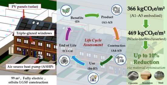
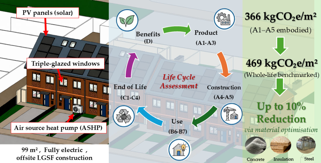
Graphical Abstract

1. Introduction

The United Kingdom faces a severe housing shortage alongside the urgent requirement to meet national net-zero carbon commitments by 2050. Around 8.4 million people live in unsuitable or unaffordable accommodation [1], while meeting housing demand would require delivering more than 440,000 homes per year, far above current construction rates [2,3,4]. This shortage is particularly acute within the social housing sector, where cost constraints, delivery speed, and long-term operational affordability are critical considerations for housing providers and policymakers [1,3]. At the same time, housing development contributes approximately 27% of national carbon emissions [5], creating a dual challenge: increasing housing supply, while reducing whole-life environmental impacts.
Off-site modular construction has emerged as a promising response to these pressures. Evidence indicates that modular systems can reduce the construction time by 30–50%, lower costs through design standardisation, and reduce on-site waste while improving quality and productivity [6,7]. These characteristics are especially relevant to social housing delivery, where rapid construction, cost predictability, and consistent quality are essential to meeting demand at scale [3,6]. International experience from Sweden, Japan, and China demonstrates the potential for high repeatability, reduced disruption, and strong energy performance [8,9,10]. However, despite these advantages, the environmental performance of modular housing, particularly its full life cycle carbon profile, remains insufficiently evidenced in the UK context.
A whole-life carbon perspective is essential because recent policy developments, such as the Future Homes Standard, have substantially reduced operational emissions [11], while embodied emissions from materials and construction account for around half of the total life cycle impacts in new low-energy homes [12,13,14]. Despite growing research on modular construction internationally [15,16,17], several important gaps remain in the UK context. Previous research highlights considerable methodological variation in building LCA studies, including differences in material databases, life cycle stage coverage, and operational modelling approaches, which can result in substantial variation in reported outcomes and affect cross-study comparability [18,19,20,21]. Embodied and operational emissions are also frequently assessed in isolation [22,23]. Furthermore, comparative assessments between steel-based modular systems and bio-based alternatives often draw on heterogeneous datasets, or inconsistent system boundaries, making it difficult to derive conclusions that are directly applicable to UK housing delivery [15,24].
To address these critical gaps, this study presents a transparent, project-specific cradle-to-grave life cycle assessment of a modular light-gauge steel frame (LGSF) residential building in Northwest England. The assessment is based entirely on primary material quantities, manufacturer Environmental Product Declarations (EPDs), and verified operational modelling inputs, using EN 15804-compliant whole-life carbon tools [25]. The case study reflects a contemporary modular dwelling typology aligned with current UK social housing priorities, where affordability, scalability, and long-term performance are central objectives [3,26].
The methodological contributions of this study are threefold:
  • A full cradle-to-grave life cycle assessment of a UK modular LGSF dwelling using real manufacturer and project data, overcoming the proxy-dominated limitations of previous studies.
  • A structured sensitivity analysis, testing alternative low-carbon materials and steel optimisation strategies to identify practical pathways for reducing upfront carbon in modular housing.
  • A hybrid operational carbon methodology, combining a SAP-verified dataset [27] with an IES VE dynamic simulation [28] to evaluate performance and uncertainty.
These contributions provide both empirical evidence and design-relevant insights for developers, engineers, and policymakers seeking to scale low-carbon modular housing in line with national climate targets [26,29]. Following this introduction, Section 2 describes the case study and LCA approach; Section 3 presents the life cycle results; Section 4 discusses findings and sensitivity analysis; and Section 5 concludes with implications for practice.

2. Materials and Methods

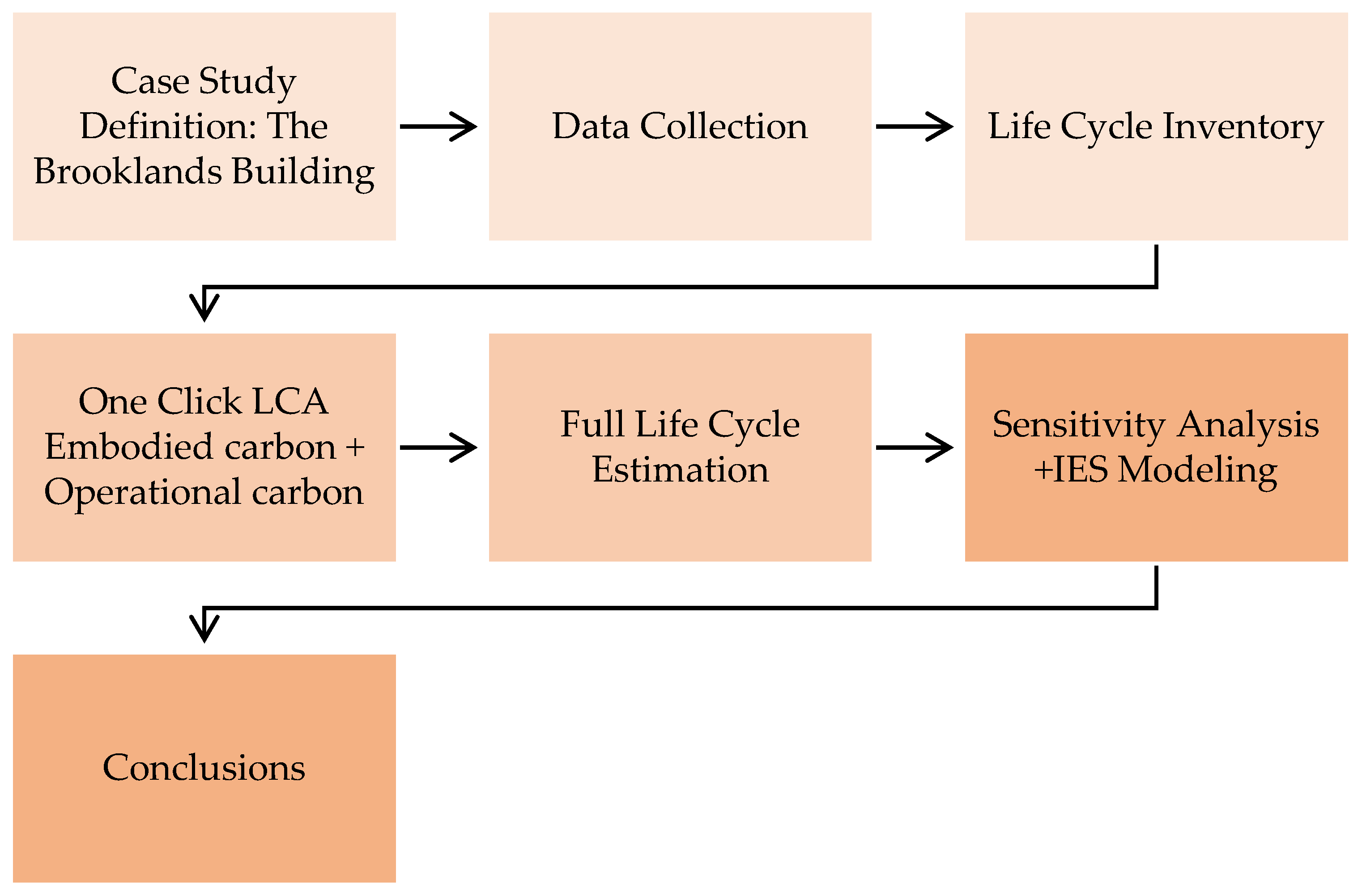
This study conducts an environmental assessment of a LGSF modular house, using a cradle-to-grave LCA methodology. The LCA process is based on the ISO 14040 and ISO 14044 standards [30], incorporating the calculation rules of BSI [31] and RICS [14]. The overall workflow (Figure 1) comprises three phases:
  • Case definition and data collection, which involved developing the material inventory and compiling geometric and material attributes based on site inspections, Revit models Autodesk Revit (Version2025.3.0, Autodesk Inc., San Rafael, CA, USA) [32] and architectural drawings.
  • Life cycle modelling and analysis, which quantified embodied impacts for stages A1–A5 using One Click LCA software (Version 4.0.9; One Click LCA Ltd., Helsinki, Finland) [33], a widely used platform for calculating and reporting the embodied and whole-life carbon impacts of buildings and construction products.
  • Sensitivity analysis, which examined the effects of design alternatives—including bio-based insulation, low-carbon concrete, foundation design, and an optimised steel frame—on total emissions. Operational energy use (stage B6) was modelled in the IES Virtual Environment (Version 2025.1.0.0, IES VE; Integrated Environmental Solutions Ltd., Glasgow, UK) [28], a software platform used to simulate building energy performance and operational carbon emissions.

2.1. Goal and Scope Definition

The goal of this study is to quantify the cradle-to-grave whole-life carbon emissions of a UK modular LGSF dwelling and to identify dominant life cycle contributors and feasible carbon reduction strategies. The intended audience includes designers, modular housing manufacturers, developers, policymakers, and researchers concerned with low-carbon residential construction.
The functional unit is defined as 1 m2 of gross internal area (GIA) of the dwelling, assessed over a 50-year reference study period, to which all life cycle inputs and outputs —including material quantities, transport emissions, construction activities, operational energy and water use, and end-of-life processes—are normalised. Although RICS [14] recommends a 60-year lifespan, a 50-year period was adopted to align with UK housing warranty conventions and to ensure consistency with previous modular housing LCA studies [34,35,36,37].
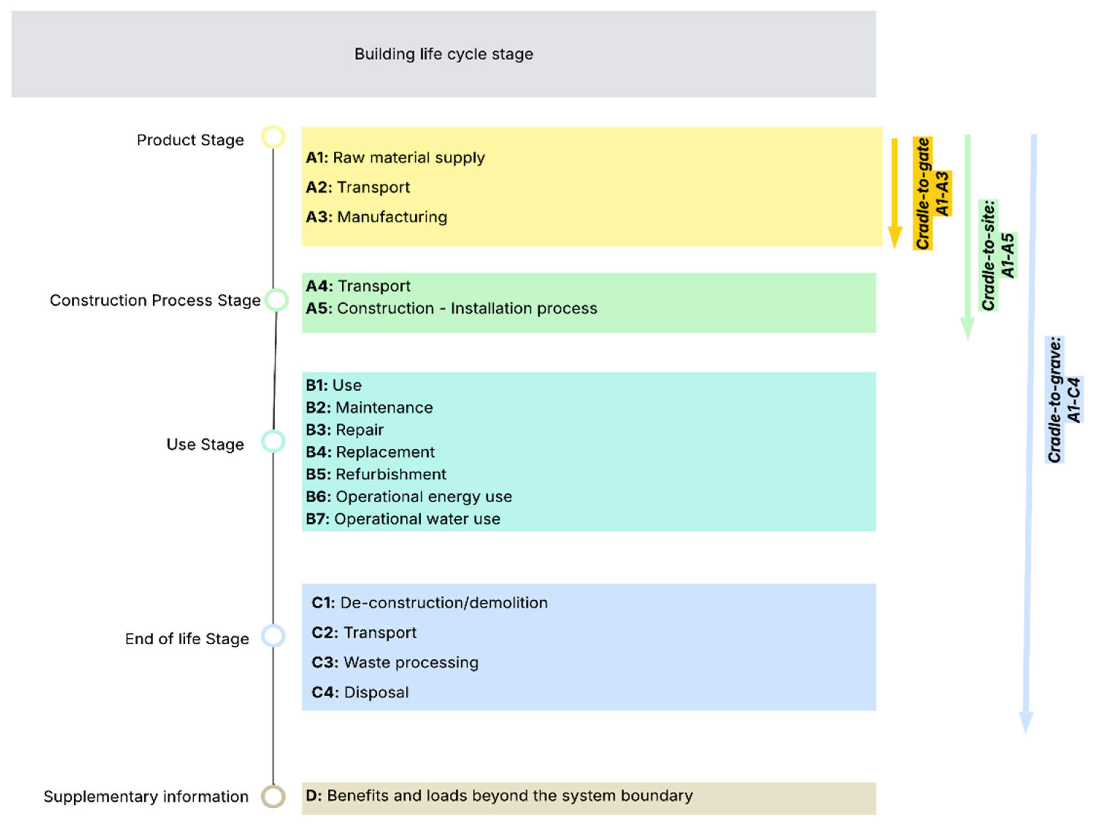
The system boundary is cradle-to-grave and includes life cycle modules A1–A5 (product and construction), B1–B7 (use stage, including operational energy and water), C1–C4 (end-of-life), and D (benefits and loads beyond the system boundary). Elements such as furniture, plumbing fixtures, lighting, and external works (e.g., fencing, paving, parking) were excluded due to limited data availability and their marginal influence on structural system comparison. Figure 2 defines the life cycle boundary applied in the assessment and clarifies which stages contribute to the reported cradle-to-grave results, ensuring transparency and reproducibility of the system boundary used.

2.1.1. Case Study

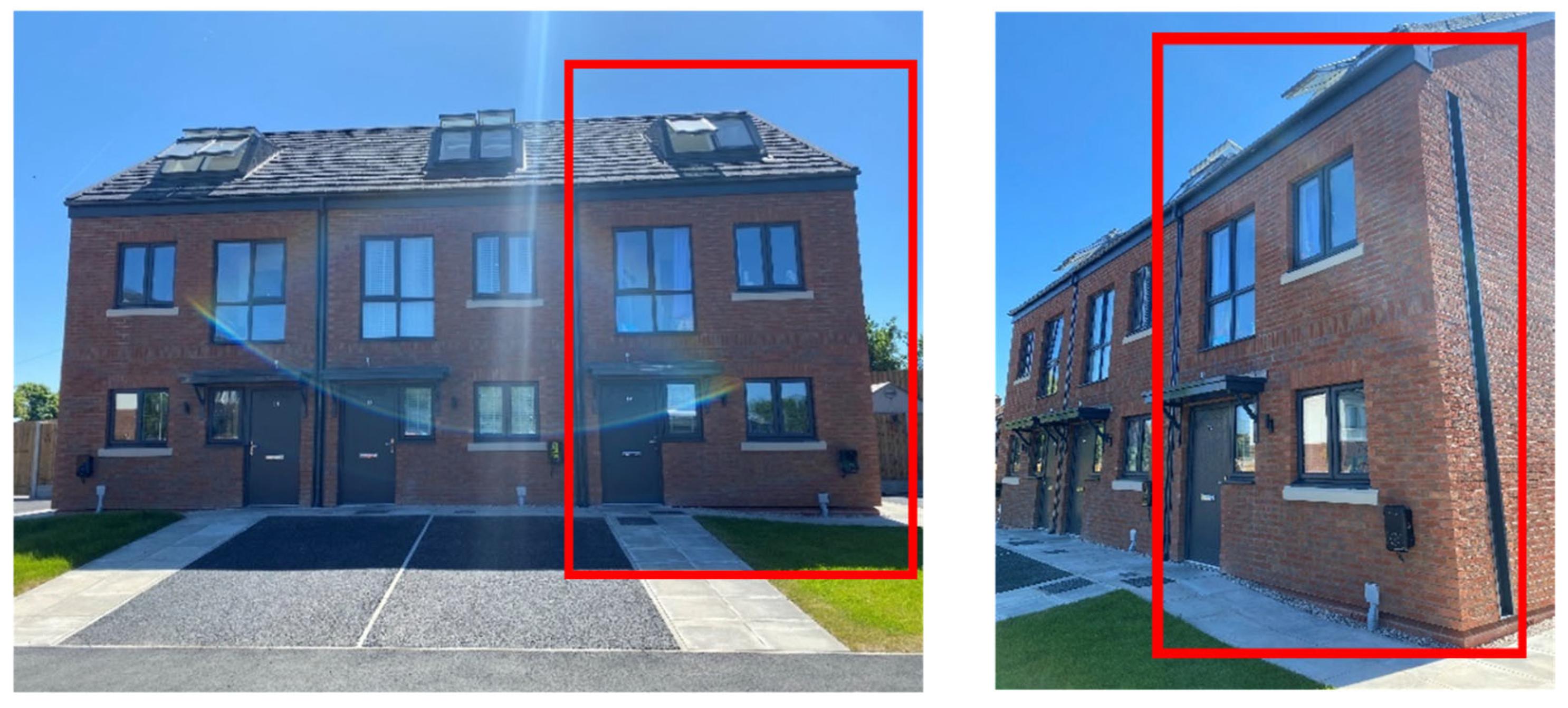
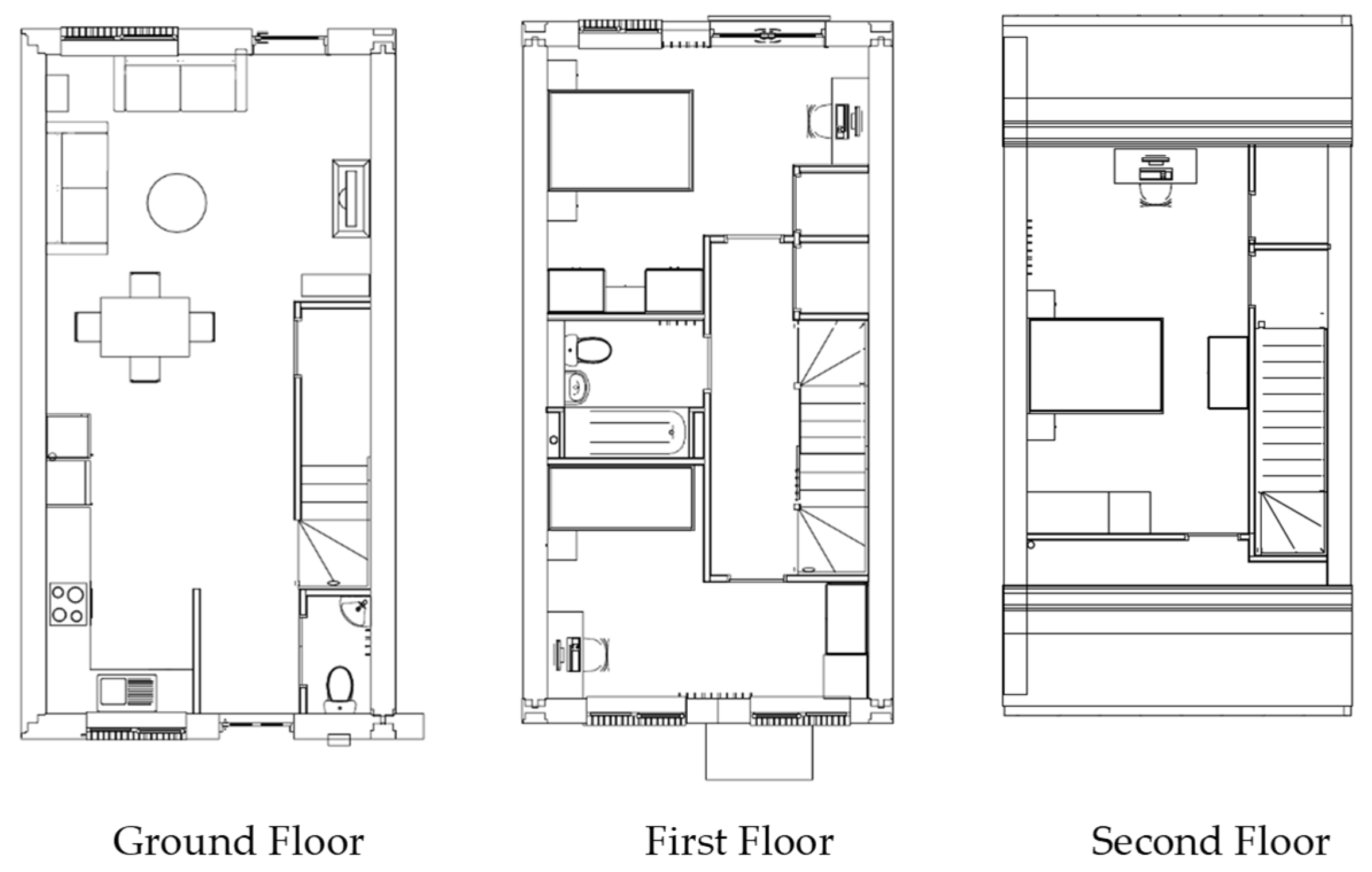
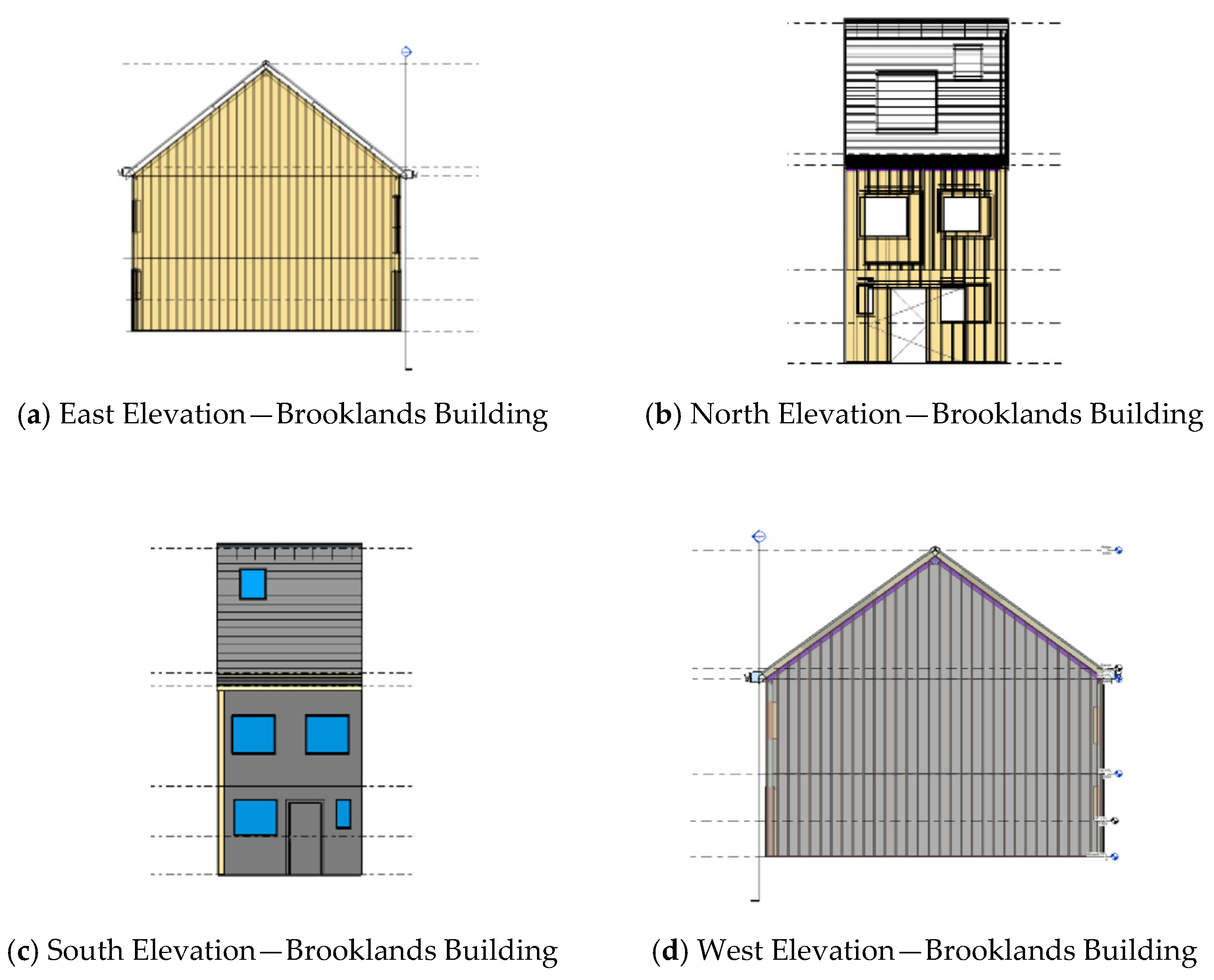
As noted by Narula and Finnegan (2025) [3], the use of the light-gauge steel frame is increasing in the UK and has the potential to meet or exceed UK national energy use ratings. Building on this context, the selected case study focuses on a modular LGSF housing development by Starship Group, located at the Brooklands site in Wirral Waters, UK [38,39]. This case study was selected because it represents a typical UK modular LGSF dwelling delivered within current social housing programmes, using standardised prefabrication, UK-compliant fabric performance, and commercially available building systems. The project comprises three zero-energy terraced houses, and one house was selected to identify the environmental impacts of a single contemporary house (Figure 3). The dwelling is a three-storey terraced house with a gross floor area (GFA) of 99 m2, containing three bedrooms, a living area, kitchen, two bathrooms and two staircases, representing a typical contemporary family home. Architectural geometry and spatial layouts were produced in Autodesk Revit by Starship Group (Figure 4 and Figure 5). Table 1 summarises the main parameters and demonstrates that the Brooklands dwelling is representative of contemporary UK social housing delivered through modular LGSF construction.
The structural system uses prefabricated light-gauge steel frame panels’ assembly, enabling rapid on-site installation. The structural frame consists of lightweight, channel-section profiles made from galvanized cold-formed steel, which are engineered for high strength-to-weight ratios [38]. Due to site-specific ground conditions, the building is supported on piled foundations with a suspended ground slab and perimeter ground beams. Walls are anchored to the slab via a proprietary Hilti M16 system, ensuring structural stability under site-specific ground conditions.
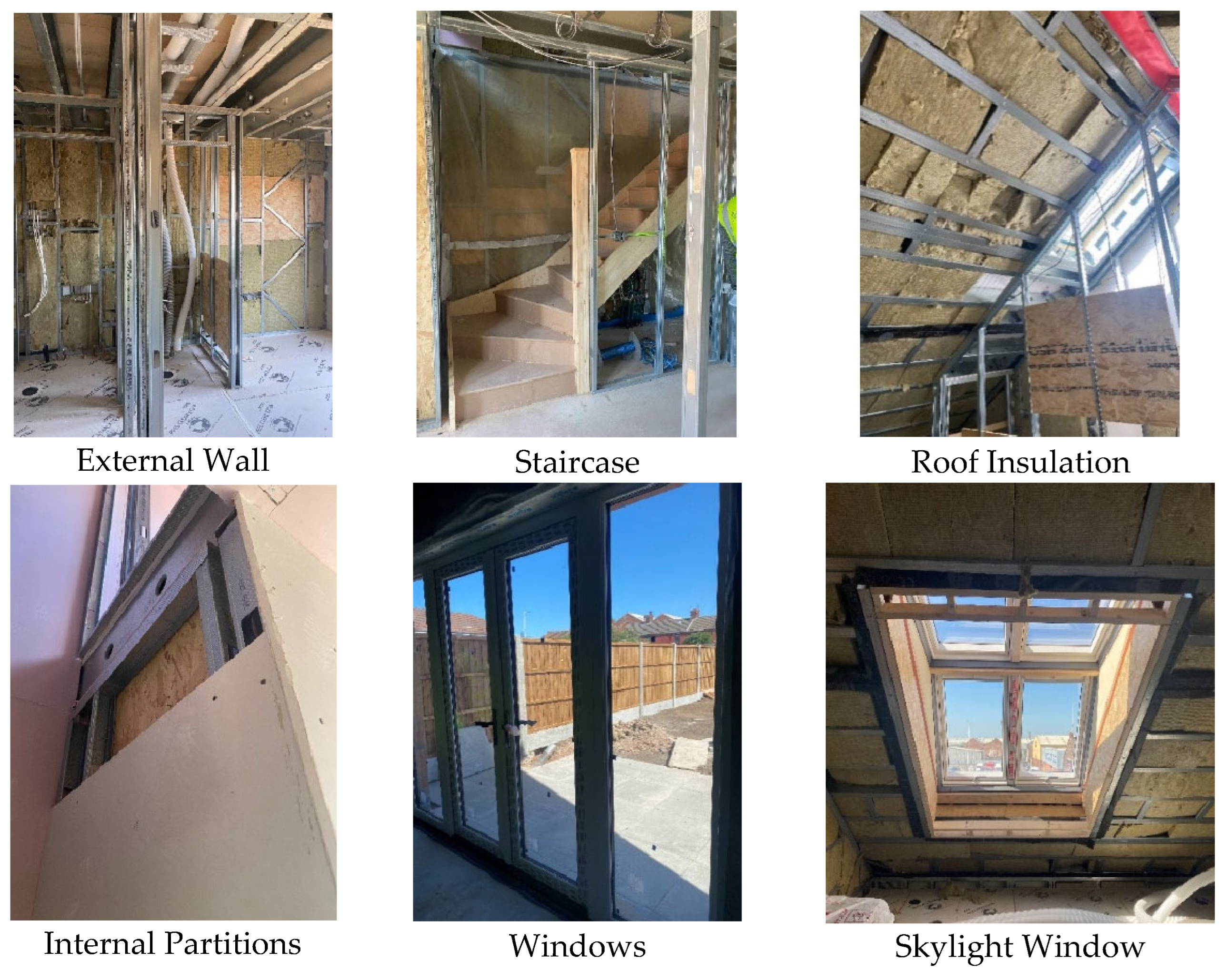
The wall panels included eight layers with a total thickness of 365 mm, with an LGSF core, inner gypsum board finish, dual insulation layers (PIR and Rockwool) [40], and a 12.5 mm sheathing board [41,42], with a 20 mm Vandersanden brick-slip cladding externally [43,44]. The specific Brick system applied by Starship Group in this type of residential house is named Pirrouet® CO2-negative facing bricks (Vandersanden, Cambridgeshire, UK) [44,45], which are able to absorb as much as 60 kg CO2 per tonne of material during the production process. Internal partitions consist of steel studs with optional mineral wool infill and plasterboard on both sides. Openings feature low-emissivity, argon-filled triple-glazed uPVC windows. The dwelling is fully electric, with no gas connection. Space heating and hot water are provided by a 3.5 kW Vaillant aroTHERM Plus ASHP (SCOP 3.65) [46] and a 150 L Unistor cylinder [47]. Ventilation combines natural openings with an MVHR unit achieving 91% heat recovery efficiency. Renewable energy is supplied by nine monocrystalline photovoltaic modules (1134 × 1950 × 30 mm each) mounted on the roof [48]. Figure 6 shows key construction elements, including wall panels, roof insulation, partitions, windows and modular stair components, all of which are included in the material inventory presented in Table 2.

2.1.2. Software and Modelling Approach

For the performance of life cycle assessment, One Click LCA software [33] which is an online platform that utilises a variety of databases, including third-party-checked EPDs, as outlined in EN 15804 [25] and ISO 14040/44 [30], was used. The software calculates environmental impacts by combining material quantities with database records and outputs indicators [49,50]. It includes four main categories of environmental data: manufacturer-specific EPDs, generic regional data, plant-specific data, and private databases.
Material selection and quantities were informed through a combination of architectural drawings, project reports, Revit model outputs [32], site visit observations, and personal consultation with the Starship Group technical team. In this study, a structured hierarchy was adopted for EPD selection to ensure representativeness and traceability: (i) manufacturer-specific EPDs were prioritised when available, (ii) if unavailable, functionally similar products from other manufacturers were selected, (iii) otherwise, UK generic EPDs were applied, and (iv) in the absence of UK data, regional European datasets (e.g., Netherlands, Belgium, France) were used.

2.2. Life Cycle Inventory (LCI)

2.2.1. Product Stage (A1–A3)

The product stage covers all cradle-to-gate process emissions for building elements and materials used in the construction of the Brooklands case study. All the 33 required materials for the case study elements were determined and populated in the One Click LCA model in this project. All collated data are reported in Table 2, where the building components are divided into broad categories, and each element includes their dimensions, quantities, embodied carbon factors, and data sources. Table 2 presents the full material inventory used in the life cycle assessment, derived from Revit model quantities, project documentation, and site verification. These quantities form the direct input to the One Click LCA model and underpin all subsequent embodied carbon calculations reported in Section 3.
Table 2. Material inventory—Brooklands case study.
ElementComponents/MaterialsOne Click LCAQuantityUnitEmbodied Carbon Factor (kgCO2e/Unit) *Transport (km)Source
FoundationGround beamsReady-mix concrete, C32/407.50 m 3 212.060Project documentation **
Ground slabReady-mix concrete, C32/406.60 m 3 212.060Project documentation
PilesReady-mix concrete, C32/401.52 m 3 290.060Project documentation
Reinforced concreteReinforcement steel cut and bent rebar2732.85kg0.7110Project documentation
Vertical Structure
External WallsVandersanden brick slip systemPerforated dense facing bricks98.32 m 2 0.3160Project documentation and manufacturer datasheet
Cement particle boardCement-bonded particle board98.32 m 2 1399.7560Project documentation
PIR insulationPIR rigid insulation boards98.32 m 2 18.480Project documentation and manufacturer datasheet
Glassroc X sheathing boardGypsum plasterboard98.32 m 2 2.0460Project documentation and manufacturer datasheet
Rockwool Flexi SlabStone wool insulation panels98.32 m 2 3.060Project documentation and manufacturer datasheet
Gyproc Fireline Board and 3 mm skimGypsum plasterboard98.32 m 2 1.5660Project documentation and site visit
Exoperm 250 self-adhesive breather membraneVapor barrier membrane98.32 m 2 1.0780Project documentation
VCL membrane behind wallboard4-layer vapour-permeable underlay0.415 m 3 1.0180Project documentation
Treated timber batten (50 × 25 mm)Green treated timber12.75kg35.0130Project documentation
Base Track-AluminiumAluminium profiles for subframe system14.5kg9.59 Project documentation
Fire Barrier_04 × 30 mmFire-resistant ventilated cavity barrier 1.32110Project documentation
Load-Bearing StructureLight-gauge steel frame (column, beam, slab)Light-gauge steel track and stud framing from hot-dipped galvanized cold-formed steel4744.76kg2.98110Project documentation
Internal Partitions Steel studs (TPS70)Wall systems with mineral wool, steel studs and gypsum plasterboards70 × 2400 mm9.3560Site visit (assumption)
Mineral wool insulation100mmSite visit (assumption)
Gyproc plasterboard2 × 12.5 mmSite visit (assumption)
Horizontal Structures
Flooring and CellingFloor screedFloor screed mortar, cement screed76.6 m 2 0.1660Project documentation and manufacturer datasheet
Rockwool insulationStone wool insulation76.6 m 2 13.060Project documentation and manufacturer datasheet
Chipboard flooringChipboard, untreated, biogenic CO276.6 m 2 69.08130Project documentation and site visit
CarpetCarpet tile--9.73130Project documentation
Damp insulationDamp insulation PA76.6 m 2 0.7180Project documentation
Gypsum plasterboard (Celling)Gypsum plasterboard76.6 m 2 1.5660Project documentation and site visit
RoofConcrete roof tilesConcrete roof tiles51.16 m 2 9.0360Project documentation
Trisomet core insulation Trisomet (sandwich panel with insulation)51.16 m 2 32.680Project documentation
Rockwool RWA45Stone wool insulation--13.060Project documentation and manufacturer datasheet
VCL 1000 gauge4-layer vapour-permeable underlay9.04m1.0180Project documentation
Gyproc FireLine boardGypsum plasterboard51.16 m 2 1.5660Project documentation
Plaster skimInterior finishing plaster51.16 m 2 0.1560Project documentation
Softwood battensTraditional roof trusses from softwood9.825 m 3 56.3130Project documentation
Ridge tileRoofing tile from clay (terracotta), ridge4.52m1.6760Project documentation
GuttersPVC rain gutters for buildings9.04m38.7110Project documentation and site visit
Others
StairsSteel modular staircaseSteel modular staircase13m115.0110Site visit (assumption)
Wooden staircaseWooden staircase2Units139.0130Site visit (assumption)
Airtight SealantAirtight sealant Joint sealants11.62Tubes15.3130Project documentation
Doors and Windows
Triple-glazed PVC frame windowTriple-glazed PVC frame window9.24 m 2 139.0130Project documentation
Modular skylight triple-glazed windowSkylight HFC 080220 0016 (Velux)5.62 m 2 227.66130Project documentation
Internal doors (11 units)Internal wooden7.84 m 2 21.5130Project documentation
External composite steel entrance doorsComposite steel entrance doors1Unit163.0130Site visit
* EPDs used within One Click LCA correspond to embodied carbon impacts at the product stage (A1–A3), based on publicly available manufacturer EPDs or equivalent verified generic datasets where manufacturer-specific data are unavailable. ** “Project Documentation” refers to confidential, proprietary data provided by Starship company and includes, but is not limited to, architectural drawings, technical specifications, and Revit model outputs.

2.2.2. Transportation Stage (A4)

Transport emissions for construction materials were calculated in One Click LCA using the UK-RICS transport scenario. This UK-specific dataset estimates transport impacts based on typical average haul distances and transport modes for different material types, rather than project-specific straight-line distances. The scenario applies a representative mix of transport modes, including road freight (diesel lorries), rail, and sea transport for imported materials, providing a realistic and standardised approach for UK-based life cycle assessments [33].

2.2.3. Construction Stage (A5)

Construction emissions were limited to excavation and modelled using UK generic datasets. Emissions from small tools and site electricity were excluded, according to EN 15978 recommendations [31].

2.2.4. Use Stage Inventory (B1–B7)

Emissions during use (B1), maintenance (B2), repair (B3), refurbishment (B4), and replacement (B5) are included by the One Click LCA tool, based on each product’s service life. The same distance and mode assumptions that were applied in transportation stage A4 were also applied for refurbishment (B4) and replacement (B5). When the precise service life was unknown, the “Technical Service Life” option was used, which is recommended by the software [33]. For example, windows were assumed to be replaced every 30 years, and floor finishes every 15 years [14].
Operational Energy—Inventory (B6)
Operational energy demand was estimated using a hybrid methodological approach, combining a SAP-verified proxy dataset, and a dynamic IES VE simulation used for sensitivity analysis, only.
Although the building had been constructed, it was unoccupied at the time of assessment and had not yet entered operational use. Consequently, no monitored energy data, utility bills, or post-occupancy performance information was available for the LCA. In this context, SAP 10.2 was adopted as the primary source of operational energy data, as it provides the only fully standardised, regulator-aligned, and reproducible method for estimating energy use in UK dwellings. The SAP-verified electricity demand dataset from the Building Research Establishment [27] was imported into One Click LCA [33] and used as the basis for operational energy inputs. While SAP is the official UK compliance method and enables transparent comparison with other UK housing LCAs, the reliance on modelled values is recognised as a limitation, since actual in-use consumption may vary due to occupant behaviour and system performance. This uncertainty is therefore explicitly examined through sensitivity analysis.
To explore potential variability, a dynamic thermal model was developed in the Integrated Environmental Solutions Virtual Environment (IES VE) [28]. The model represented the as-built geometry, fabric performance, HVAC configuration, airtightness assumptions, occupancy schedules, and photovoltaic generation under typical meteorological conditions for Liverpool. The dwelling was modelled as fully electric, with space heating and domestic hot water provided by a 3.5 kW air-source heat pump (SCOP 3.65) [46] and a 150 L hot water cylinder [47], supplemented by a 4.62 kWp rooftop photovoltaic system [48]. As post-occupancy monitoring data were not available, the IES VE model could not be calibrated and was therefore not used to generate primary LCA inputs. Instead, it was employed solely to assess uncertainty and potential variation in operational performance, as discussed in Section 4.3. Key IES modelling parameters and assumptions are summarised in Table 3 to ensure transparency and reproducibility.
Operational Water Use—Inventory (B7)
Operational water use followed Part G of the UK Building Regulations, assuming 150 L/person/day for a five-person household over 50 years. Emissions for tap water and wastewater treatment used One Click LCA’s UK generic datasets.

2.2.5. End-of-Life Stage (C1–C4)

The end-of-life stage includes deconstruction/demolition (C1), transport to waste-treatment facilities (C2), processing for recycling or recovery (C3), and final disposal of non-recoverable materials (C4). Deconstruction was modelled as mechanical disassembly using standard UK industry default assumptions [25], with waste transport distances of 60–130 km depending on the material stream. For end-of-life modelling, the “Material locked (recommended)” option was selected in One Click LCA to ensure consistency with EN 15804 and EN 15978 guidance [25,51]. This approach applies standardised, sector-average assumptions for deconstruction, transport, processing, and disposal, recognising the inherent uncertainty of future demolition pathways and avoiding speculative optimisation of end-of-life scenarios, as recommended in the LCA methodology literature [18,52].
Recycling and recovery rates were derived from verified Environmental Product Declarations (EPDs) and standard industry-average end-of-life scenarios, as no project-specific manufacturer take-back schemes were available. These include ≥95% recycling for steel, energy recovery for PIR insulation, and partial aggregate reuse for concrete, reflecting current European and UK waste management practices [22,23,35,49]. It is acknowledged that, in the absence of national take-back schemes or contractual commitments, actual future recycling performance may differ from these assumed values.
A summary of end-of-life and recycling assumptions is provided in Table 4. As Module D results are known to be highly sensitive to these assumptions [18,26,52], they are reported separately and interpreted as indicative rather than definitive, while primary conclusions are based on cradle-to-grave impacts (Modules A–C).

3. Life Cycle Impact Assessment (LCIA)

3.1. LCA Results per Life Cycle Stage

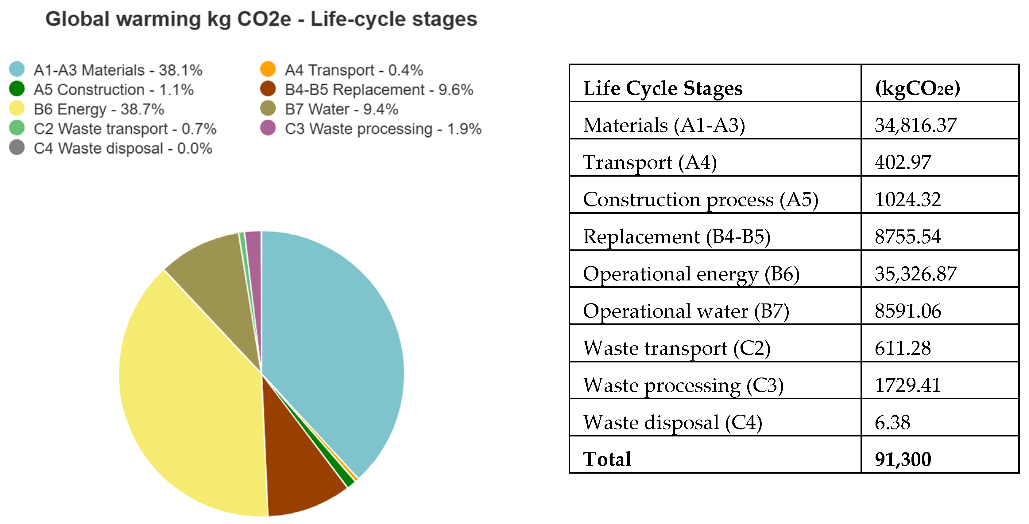
This section presents the life cycle carbon results for the Brooklands modular house, classified by standard LCA stages in accordance with EN 15978 [31] and the RICS Whole-life Carbon methodology [14]. The results for each life cycle stage are shown in Figure 7. The figure illustrates the relative contribution of each stage to total whole-life carbon, enabling rapid identification of the dominant emission sources and highlighting the balance between embodied and operational impacts. The total whole-life carbon footprint of the Brooklands unit amounts to 91.3 tCO2e over a 50-year reference study period, equivalent to 18.4 kgCO2e/m2/year or 922 kgCO2e/m2 of gross internal floor area. When considering stages A1-A5, the normalised embodied carbon intensity is equal to 366 kgCO2e/m2, whilst the total A1–A3 embodied carbon of the Brooklands development is 34.82 tCO2e, equivalent to 351.68 kgCO2e/m2 GIA. The largest contributors are the product stage (A1–A3) at 34.8 tCO2e (38.1%) and operational energy (B6) at 35.3 tCO2e (38.7%). Together, these account for more than three-quarters of the total impact, underscoring that both upfront material choices and operational efficiency are equally critical in modular housing decarbonization [53]. Operational water use (B7) adds 8.6 tCO2e (9.4%), highlighting the significance of water-related impacts, which are often underreported or inconsistently assessed in building LCAs [54]. This value is based on regulated domestic water consumption derived from SAP 10.2 calculations, incorporating assumed occupancy rates and standard UK emission factors for water supply and wastewater treatment. Although frequently considered secondary to operational energy (B6), the results demonstrate that water-related emissions are not negligible over a 50-year reference study period, consistent with recent LCA evidence [55].
In contrast, transport (A4) (0.402 tCO2e) and construction processes (A5) (1.02 tCO2e) together contribute less than 2% of the total. Transport emissions reflect the local/regional sourcing of materials, which is typical of modular construction projects and helps reduce upstream carbon impacts [35]. A5 also represents a small share, which shows the efficiency benefits of modular assembly compared with traditional construction [56]. Similarly, end-of-life (C1–C4) emissions are relatively minor at 2.3 tCO2e (2.6%), partly due to the potential recyclability of steel components [53], reflecting the inherently dismantlable nature of modular construction, which allows major elements to be selectively removed rather than destructively demolished [52].
Beyond global warming, the LCA also considered additional impact categories in accordance with EN 15978 [31] and ISO 14040/44 [30]. Table 5 presents these indicators, including ozone depletion, acidification, eutrophication, formation of ozone of lower atmosphere (POCP), abiotic depletion potential (ADP) for non-fossil resources, and abiotic depletion potential (ADP) for fossil resources [57]. The results reveal notable non-carbon pressures. In particular, fossil resource depletion is high at 670,000 MJ, reflecting the reliance on energy-intensive steel and concrete. Acidification potential reaches 263 kg SO2e, largely attributable to upstream electricity and cement processes. Eutrophication impacts (231 kg PO4e) highlight risks to water quality, while ozone depletion, though small in absolute terms (0.024 kg CFC-11e), remains environmentally significant.

3.2. Embodied Carbon: Stages A1–A3

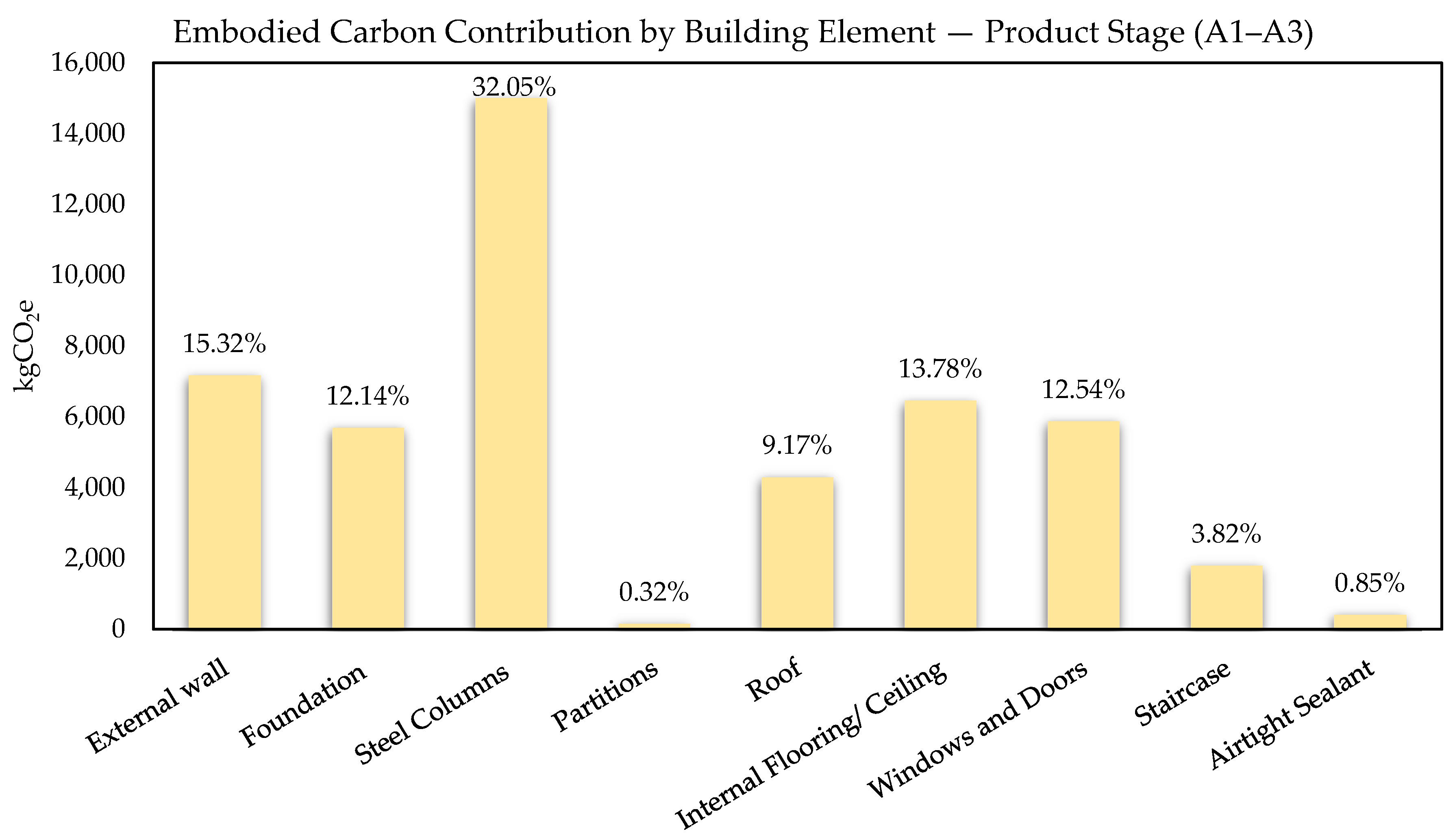
The total A1–A3 embodied carbon for the Brooklands unit is 34.82 tCO2e, equivalent to 351.68 kgCO2e/m2 GIA, which is already well below the RIBA 2025 (800 kgCO2e/m2) and 2030 (625 kgCO2e/m2) limits [58], and close to the LETI 2030 best-practice target of 300 kgCO2e/m2 [59]. Figure 8 shows the relative contribution of each element to the total embodied carbon for the A1–A3 stages. At the element level, the steel frame contributes 32%, highlighting the structural system as the largest hotspot. This reflects the high energy intensity of steel production, consistent with previous findings in modular housing LCAs [60,61,62]. Structural steel was modelled as hot-dipped galvanised cold-formed light-gauge steel using manufacturer-specific or equivalent EN 15804-compliant EPDs [25], consistent with UK LGSF modular construction practice. Other significant shares include external walls (15.32%), internal floors/ceilings (13.78%), and foundations (12.14%), while partitions and airtight seals make negligible contributions.
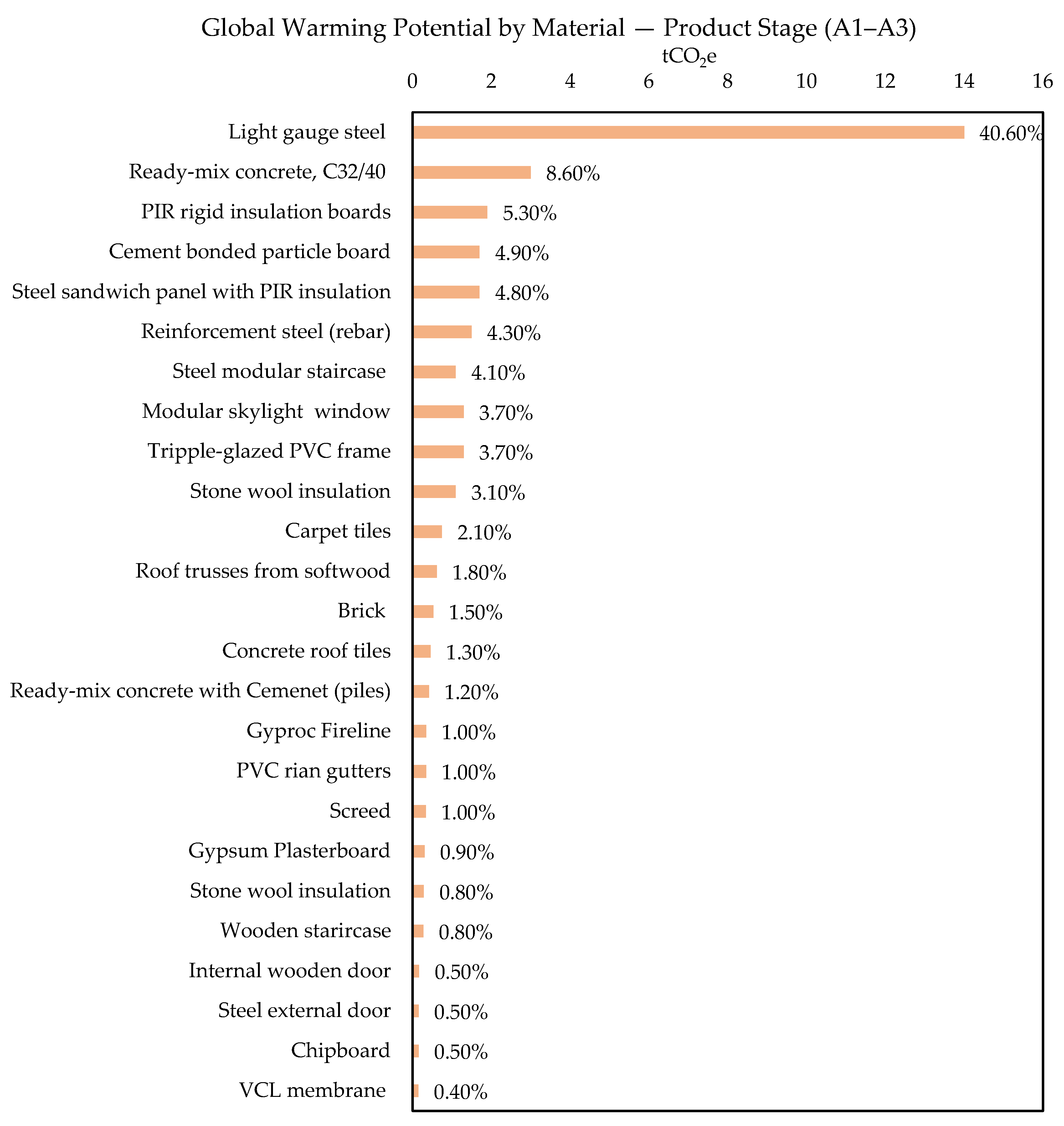
Figure 8 shows that embodied carbon is heavily concentrated in primary structural and envelope components. Beams and slabs also carry a large share, primarily due to ready-mix concrete. To further dissect these impacts and identify specific material-level hotspots within the product stage (A1–A3), Figure 9 shows the embodied carbon per material. The material breakdown confirms that light-gauge steel alone contributes 40.60% of total A1–A3 impacts. Other significant contributors are concrete slabs and ground beams (8.60%), PIR rigid insulation boards (5.30%), and glazing units (7–8%).
To improve comparability with other studies, the three dominant material contributors at the product stage (A1–A3), from Figure 9, were further normalised using the functional unit. Based on a gross internal floor area of 99 m2 and a 50-year reference study period, light-gauge steel contributes approximately 141.4 kgCO2e/m2 (2.83 kgCO2e/m2/year), ready-mix concrete (C32/40) contributes 30.3 kgCO2e/m2 (0.61 kgCO2e/m2/year), and PIR rigid insulation boards contribute 19.2 kgCO2e/m2 (0.38 kgCO2e/m2/year). Given their dominant contribution to A1–A3 impacts, these materials were selected as baseline components for the sensitivity analysis presented in Section 4.2.
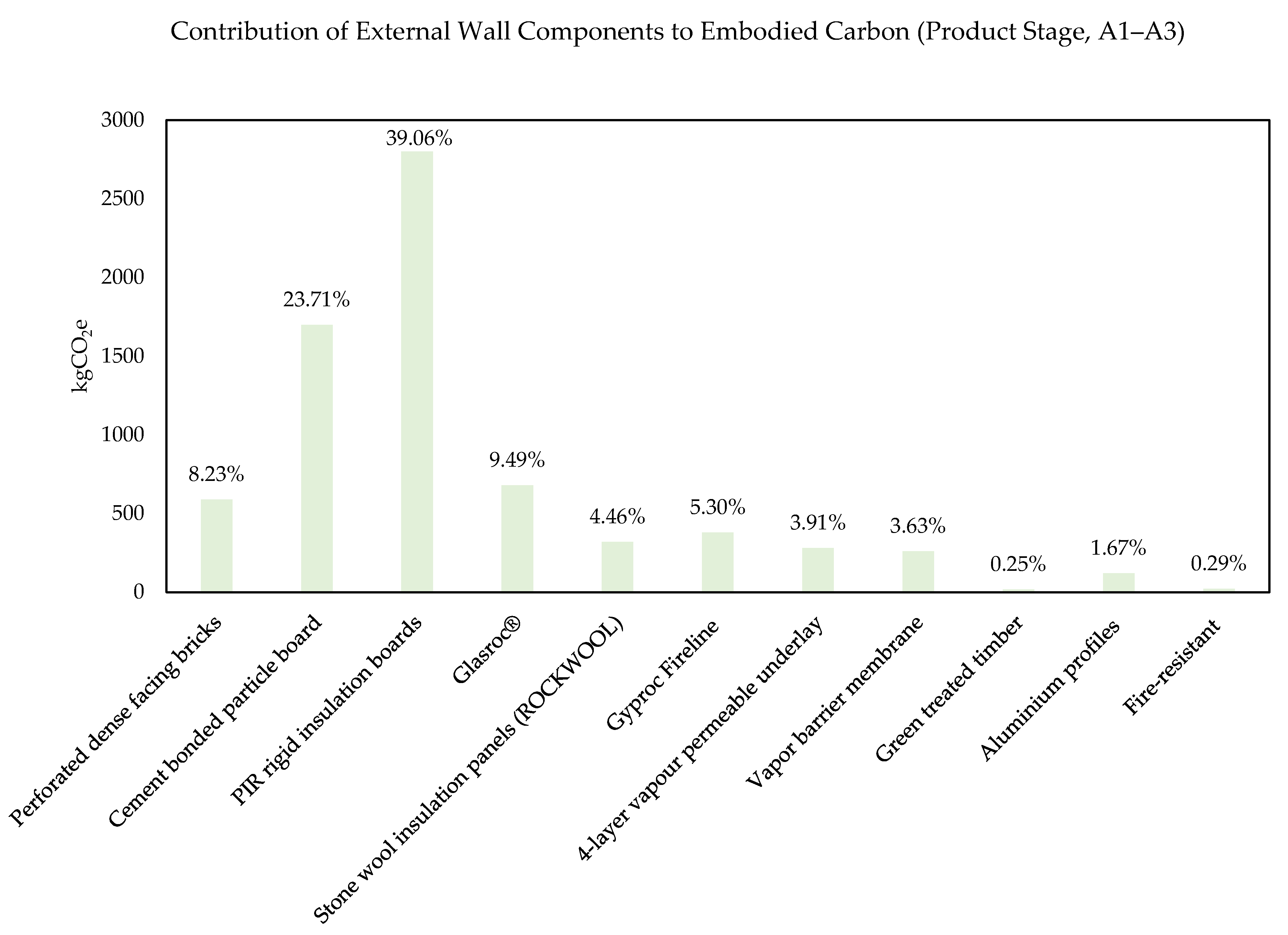
External walls account for the second-highest share of total embodied carbon. The contribution of each external wall component to the total embodied carbon at the A1–A3 stage is presented in Figure 10. This wall panel comprises ten layers, of which the PIR rigid insulation boards account for 39.06% (2.8 tCO2e) of the panel’s embodied carbon (2.8 tCO2e) (Figure 10). This is due to the high Global Warming Potential (GWP) of rigid petroleum-based foam insulation, which, while offering excellent thermal performance, carries a higher manufacturing footprint. The cement-bonded particle board is the next largest component at 23.71% (1.7 tCO2e), followed by Glassroc® sheathing boards at 9.49%.

3.3. Operational Carbon: Stage B6–B7

Operational carbon over the 50-year study period totals 43,917.9 kg CO2e, representing 48.1% of the whole-life carbon footprint. This consists of the following:
  • 35,326.87 kg CO2e (38.7%) from household electricity consumption (B6);
  • 8591.06 kg CO2e (9.4%) from operational water use (B7).
These values are based exclusively on the SAP 10.2 proxy dataset, ensuring alignment with UK regulatory practice and maintaining reproducibility [27]. SAP 10.2 provides a standardised, regulator-aligned, and reproducible method for estimating operational energy use in UK dwellings, avoiding the uncertainty of uncalibrated simulations. To complement this baseline assessment, the IES VE model was used to explore uncertainty and performance variability, with the results presented separately in Section 4.3.

3.4. Module D: Beyond the System Boundary

Module D, which quantifies benefits and loads beyond the system boundary, provides an essential perspective on the building’s role within a circular economic framework. This stage evaluates the potential environmental credits (or burdens) arising from reuse, recycling, and energy recovery that occur beyond the declared life cycle boundary (C4), thus displacing the need for virgin material production in future systems. For the Brooklands modular case study, Module D yields a net GWP credit of −6.89 tCO2e. The largest contributor to this credit is the recovery of high-impact structural components, primarily light-gauge steel framing (−5.88 tCO2e), which account for over 85% of the Module D benefit. The credit of −6.89 t CO2e offsets approximately 29% of the total cradle-to-grave embodied carbon (A1–C4 = 23.47 tCO2e), exceeding the combined burdens from the C-stage processes. This outcome highlights how modular construction can facilitate material recirculation and measurable carbon recovery within the built environment, consistent with prior findings by [56].

4. Interpretation

4.1. Discussion and Benchmarking

The whole-life carbon results of the Brooklands modular dwelling highlight the dual significance of both upfront embodied impacts and long-term operational performance in the carbon profile of contemporary UK housing. The product stage (A1–A3) accounted for the largest share of emissions, driven primarily by steel-intensive elements, such as the light-gauge steel frame and foundation components. These findings align with recent research showing that structural systems often dominate early life cycle impacts in buildings [49,63]. When operational performance is considered over the building’s service life, operational carbon is estimated to represent approximately 48.1% of total life cycle emissions, reflecting the influence of the high-efficiency building envelope, triple-glazed openings, air-source heat pump, and on-site solar generation. This combined assessment supports emerging evidence that low-energy modular homes can substantially reduce lifetime environmental impacts, when fabric and energy systems are designed in an integrated manner [59,64].
Benchmarking whole-life carbon performance across residential buildings is inherently challenging due to differences in functional units, system boundaries, reference study periods, material specifications, and operational modelling assumptions. As a result, comparisons between published studies are most appropriate for assessing the plausibility and order of magnitude rather than strict numerical equivalence.
A normalised comparison of upfront embodied carbon intensity (A1–A5), expressed per unit floor area, can be drawn between the Brooklands case study and a recent CLT multi-storey building reported by Dodoo et al. [16]. The CLT study reports an embodied carbon intensity of approximately 300 kg CO2e/m2, while the Brooklands modular dwelling exhibits a value of 366 kg CO2e/m2 based on the sum of A1–A5 impacts divided by its gross floor area of 99 m2. Keyhani et al. [65] have shown substantial variability in embodied carbon results depending on database selection and end-of-life assumptions, with product-stage values exceeding 500 kg CO2e/m2 in some UK residential scenarios [65]. Within this broader context, the Brooklands results fall within the range reported for best-practice low-carbon residential construction.
Additional contextual benchmarking with UK and international LCAs of steel- and hybrid-framed dwellings shows typical upfront embodied carbon intensities of approximately 350–550 kg CO2e/m2 for A1–A5 [26,34,35,63], placing the Brooklands case study toward the lower end of reported values for steel-based systems. This reflects the benefits of off-site fabrication and reduced construction waste.
The reported whole-life carbon intensity of the CLT case study [16] is 465 kg CO2eq/m2, accounting for stages A1–A5, B1–B2, B4, and C1–C4. The Brooklands case study yields a similar order of magnitude at 469 kg CO2eq/m2; however, this value is derived from a different combination of life cycle stages (A1–A4, B4–B5, and C1–C4). Hence, these figures are derived from different combinations of life cycle stages and should therefore be interpreted as indicative rather than directly comparable. Taken together, the benchmarking indicates that the Brooklands modular LGSF dwelling performs within the upper tier of reported UK residential case studies and achieves whole-life carbon outcomes comparable to leading low-carbon timber and hybrid systems. This supports the conclusion that well-designed modular steel construction can deliver a competitive whole-life carbon performance when material efficiency and operational energy demand are addressed holistically.
To evaluate the robustness of these findings and to optimise the performance, a sensitivity analysis was undertaken covering both embodied and operational aspects. For embodied carbon, alternative scenarios were developed for the three material groups with the highest A1–A3 contributions: foundation concrete (lower-carbon mixes), insulation (five bio-based options), and structural steel (profile optimisation). These reflect realistic design variations consistent with EN 15978 [31] and RICS [14] guidance on scenario testing. Operational carbon sensitivity was assessed using the IES VE dynamic simulation and a ±10% variation around the base annual electricity demand, capturing typical uncertainties related to modelling assumptions and real-world performance. The following subsections present the embodied and operational sensitivity scenarios in detail.

4.2. Embodied Carbon: Interpretation and Sensitivity Analysis

This subsection evaluates the sensitivity of the Brooklands embodied carbon results by modelling three improvement scenarios targeting the main contributors identified in the baseline assessment: the concrete foundations, thermal insulation, and structural steel frame. These elements were selected as they offer practical opportunities for reducing upfront carbon through alternative specifications or design optimisation. The scenarios were implemented using EPDs available in One Click LCA, including some non-UK datasets, which are acknowledged as a limitation. Table 6, Table 7 and Table 8 report scenario-based sensitivity results rather than predictive outcomes, illustrating the relative magnitude of potential carbon reductions achievable through alternative material specifications and structural optimisation.

4.2.1. Foundation Concrete

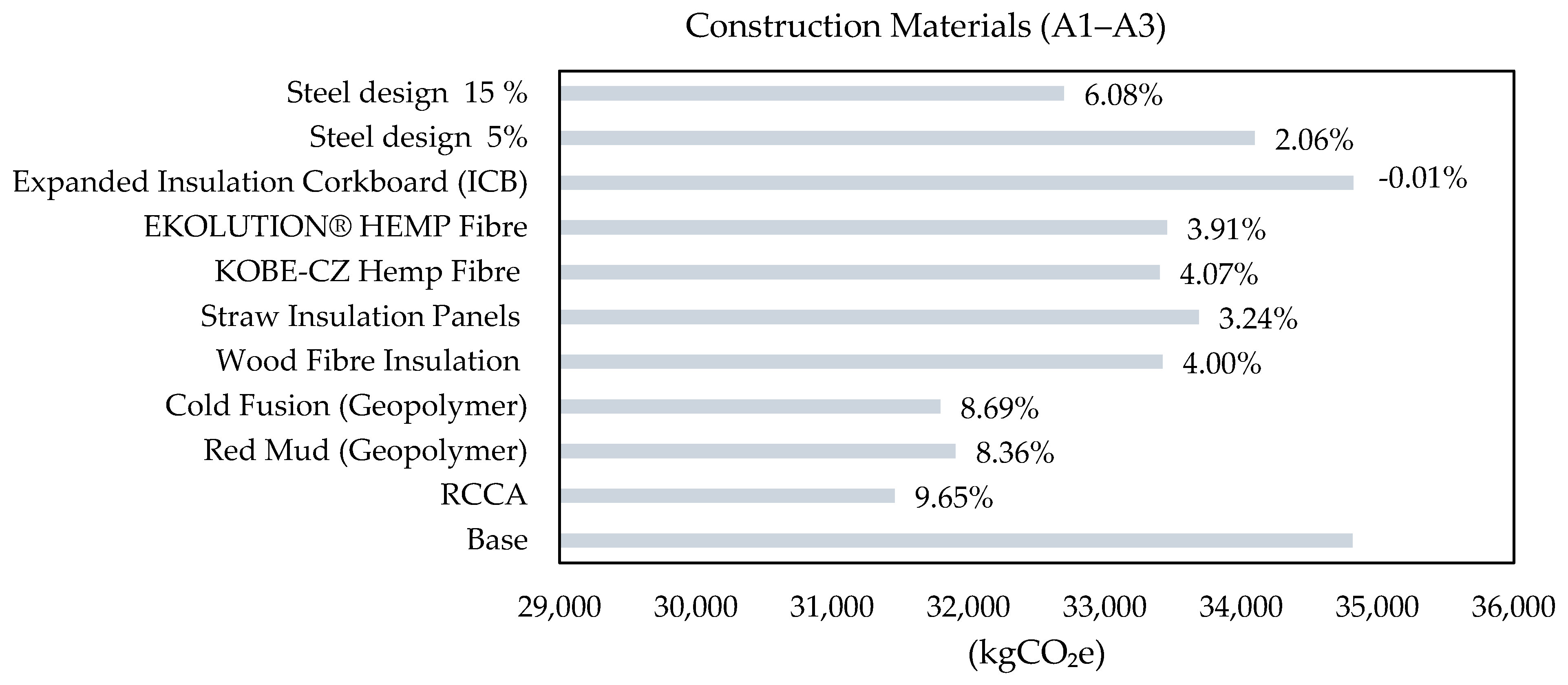
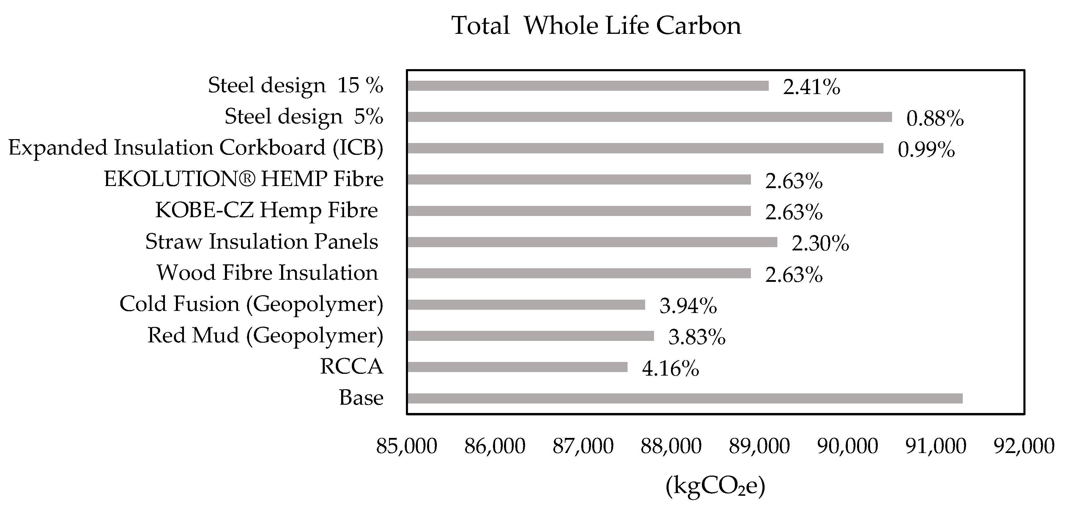
The foundation system is one of the most carbon-intensive building elements due to its high Ordinary Portland Cement (OPC) content. Three alternative mixes were modelled: a recycled crushed concrete aggregate (RCCA) mix and two geopolymer concretes (red mud and cold fusion), and the comparison is shown in Table 6. These substitutes reflect viable low-carbon options increasingly examined in the literature [66,67]. The RCCA scenario produced the largest reduction in A1–A3 emissions, lowering foundation impacts from 34,816 kgCO2e to 31,457 kgCO2e, a 9.65% reduction. The geopolymer options reduced emissions by ~8.4–8.7%, also decreasing the foundation’s share of whole-life carbon. These improvements stem from replacing virgin aggregates and OPC with recycled or industrial by-product materials, consistent with circular economy principles [68,69]. It should be noted that the use of geopolymer concrete in this study reflects technical potential rather than compliance-ready solutions within current UK regulatory frameworks.
Table 6. Comparison of embodied carbon impacts for concrete foundation alternatives.
ScenarioEmbodied Factor (A1–A3)A1–A3 (kgCO2e)Total Whole-Life Carbon (kgCO2e)%A1–A3 Reduction% WLC
Reduction
Country
C32/40 Concrete (Base)212.0 kg CO2e/m334,816.3791,300.00 --UK
RCCA Concrete0.0008 kg CO2e/kg31,457.0987,500.009.65%4.16%NZ
Red-Mud Geopolymer 0.30 kg CO2e/kg31,904.7087,800.008.36%3.83%USA
Cold-Fusion Geopolymer0.27 kg CO2e/kg31,791.6887,700.008.69%3.94%USA

4.2.2. Insulation: Bio-Based Alternative

The baseline insulation, PIR rigid boards, accounts for approximately 5.3% of whole-life carbon. Five bio-based alternatives were modelled: wood fibre, straw panels, hemp fibre (two product variants), and expanded corkboard, and the results are shown in Table 7. Each alternative was adjusted in thickness to maintain the equivalent thermal resistance and U-value. Wood fibre and the two hemp options achieved the strongest reductions, lowering A1–A3 emissions by 1.36–1.42 tCO2e (4.0–4.07%). Straw insulation reduced emissions by ~1.13 tCO2e (3.24%). Corkboard showed higher emissions due to an EPD that did not account for biogenic storage, suggesting further work is required to evaluate cork’s full carbon profile [70]. Across the alternatives, total whole-life emissions decreased by 2.1–2.6 tCO2e, demonstrating that switching from petrochemical to bio-based insulation can significantly lower embodied carbon without altering performance. This aligns with recent research highlighting the climate benefits of bio-based materials in housing [35,71].
Table 7. Comparison of embodied carbon impacts for PIR and bio-based insulation alternatives.
ScenarioEmbodied
Carbon Factor
(A1–A3)
A1–A3 (kgCO2e)Total Whole-Life Carbon (kgCO2e)%A1–A3 Reduction% WLC
Reduction
Country
Base (PIR)18.40 kg CO2e/m234,816.3791,300.00--France
Wood fibre boards2.38 kg CO2e/m233,422.2288,900.004.00%2.63%Germany
Straw panels8.90 kg CO2e/m233,689.5089,200.003.24%2.30%Lithuania
KOBE-CZ hemp fibre2.18 kg CO2e/m233,400.9188,900.004.07%2.63%Czech Republic
EKOLUTION® hemp fibre2.18 kg CO2e/m233,455.2788,900.003.91%2.63%Sweden
Expanded corkboard (ICB)87.0 kg CO2e/m334,821.2390,400.00−0.01%0.99%Portugal

4.2.3. Steel: Optimised Structural Steel Design

Steel is the largest contributor to the Brooklands embodied carbon footprint, accounting for approximately 32.05% of the total whole-life carbon (total steel mass of 4744.76 kg). The rolling form data shows that the largest share of steel in this modular house comes from the profiles used for floors (C250-65-1.6, 1562.2.6 kg) and roofs (C200-65-1.6, 971.74 kg), with wall framing being also significant (C100-41.3-1.6, 1955.8 kg). This shows that optimising the design of floor and roof beams offers potential for embodied carbon savings in the structural system.
Optimised cold-steel profiles and higher steel grades could allow a reduction in structural steel weight without compromising structural integrity [72]. Experimental and numerical research on cold-formed steel members has demonstrated that profile optimisation can significantly improve structural efficiency, allowing material reductions while maintaining strength and serviceability performance [73]. In addition, the adoption of advanced system-based design methods has been shown to result in lighter and more economical designs, with material requirement reductions of up to 15% [62]. The 5% and 15% steel reduction scenarios were selected to represent lower- and upper-bound ranges of potential structural optimisation. These values are intended to explore the sensitivity of embodied carbon results to reasonable improvements in design efficiency, rather than to predict specific as-built reductions [73].
To test the potential for practical reductions, this scenario models a 5% and 15% reduction in total steel mass, and the results are shown in Table 8. The results demonstrate that an optimised structural steel design system can significantly reduce embodied carbon emissions during the A1–A3 stages [62]. A moderate optimisation scenario achieves a 2.1% reduction in A1–A3 embodied carbon, while a more aggressive approach delivers over 6% savings at this stage alone. Since steel production represents the largest carbon contributor in the Brooklands modular house, these reductions are particularly impactful.
Table 8. Optimised structural steel design and structural steel embodied carbon and total whole-life carbon footprint.
ScenarioA1–A3 (kgCO2e)% Steel Share of Whole-Life CarbonTotal Whole-Life Carbon (kgCO2e)%Reduction
A1–A3 (kgCO2e)
Base34,81632.05%91,300-
5% less-steel design 34,10030.57%90,5002.09%
15% less-steel design 32,70027.40%89,1006.11%

4.2.4. Summary of Alternative Reductions to Embodied Carbon

Figure 11 and Figure 12 summarise the impact of all embodied carbon scenarios. The foundation alternatives delivered the greatest reductions (up to 9.65% in A1–A3 and 4.16% in whole-life carbon), followed by bio-based insulation (reductions of 2.3–2.6% in whole-life carbon). Steel optimisation achieved additional reductions of 0.9–2.4%. Combined, these results show that early-stage material selection can reduce embodied emissions by up to ~10%, supporting a pathway toward lower-carbon modular construction. The combined reduction of approximately 10% represents an indicative upper-bound scenario, derived by aggregating individual measures rather than modelling their simultaneous implementation within a single integrated design.

4.3. Operational Carbon (B6): Interpretation and Sensitivity Analysis

The IES VE model developed in Section 2.2.4 provided an alternative estimate of the dwelling’s operational energy use and was employed here solely for sensitivity analysis. The model predicted a total delivered energy intensity of 57 kWh/m2·yr, which lies within both the CIBSE TM54 [64] and LETI benchmark [59] ranges for new-build EPC Band A dwellings (50–60 kWh/m2·yr), and aligns with the RIBA 2030 [58] intermediate performance target. In the primary life cycle assessment results, operational carbon emissions (B6) are based on SAP 10.2-derived electricity demand without applying photovoltaic (PV) export credits, in line with UK regulatory reporting practice. Although the case study building is equipped with PV, its generation is incorporated only within the IES VE model and used in this section to explore potential reductions in net delivered energy.
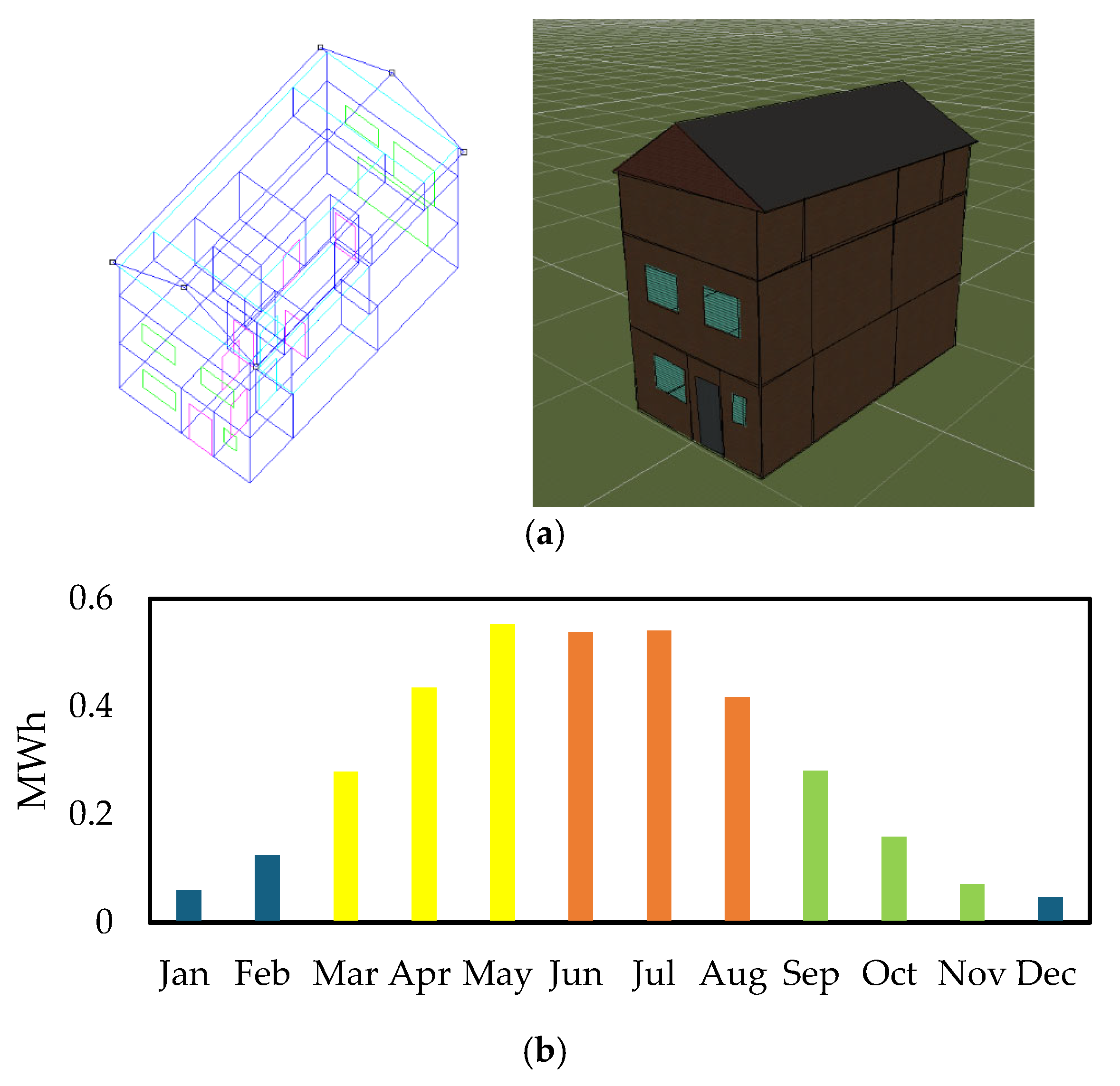
When on-site solar generation was included, the model yielded a net delivered energy of approximately 2430 kWh/year, corresponding to a Net Energy Use Intensity (EUI) of 24 kWh/m2·yr. Figure 13 illustrates the monthly PV generation profile, showing strong seasonal variation, with a peak output of 0.55 MWh in May and 0.06 MWh in January. This seasonal pattern highlights the importance of storage and grid integration to maintain stable net-zero operational performance. Validation against LETI benchmark ranges showed strong agreement for space heating, domestic hot water and lighting (Table 9), supporting the plausibility of the model. The heat pump seasonal coefficient of performance (SCOP = 3.65) is based on manufacturer data and aligns with the annualised value applied within SAP 10.2, ensuring consistency between regulatory energy assessment and sensitivity-based modelling.
The building envelope supports this low operational demand: walls and roof achieve low U-values, all windows are triple-glazed with uPVC frames, and the glazing ratio is approximately 14.86 m2, including a large roof light (5.62 m2) on the third floor to maximise daylight and reduce reliance on artificial lighting. Collectively, high insulation, airtightness, and efficient lighting help maintain comfort while minimizing energy use [74]. Given the absence of measured energy data, a ±10% variation was applied to the base SAP-derived demand to represent typical performance gap uncertainty (commonly 5–30% in UK dwellings) [75]. This enables a realistic range of operational carbon outcomes without relying entirely on an uncalibrated dynamic model. In comparison with the SAP baseline (35,326 kgCO2e), the IES VE scenario reduces operational carbon to 25,159 kgCO2e, representing an approximate 29% reduction under favourable performance and photovoltaic generation conditions. Results of the ±10% scenarios, and the standalone IES VE scenario, are presented in Table 10.

5. Conclusions and Future Research

This study assessed the whole-life carbon performance of the Brooklands modular dwelling, demonstrating how a light-gauge steel frame system can deliver low-carbon outcomes when supported by fabric-efficient design and optimised material specification. Using primary construction data within a reproducible LCA framework, the analysis shows that the dwelling achieves a normalised carbon intensity of 469 kgCO2e/m2 across the reported life cycle stages A1–A4, B4–B5, and C1–C4. When expressed for the product and construction stages (A1–A5), the embodied carbon intensity is 366.09 kgCO2e/m2, which is of a similar order of magnitude to values reported for recent high-performing CLT buildings. This comparison is intended as contextual benchmarking rather than direct equivalence, reflecting differences in building typology, scale, and modelling assumptions, and indicating that modular steel systems can achieve upfront carbon levels typically associated with bio-based construction.
The distribution of impacts, with 38.2% arising from embodied emissions and 48.1% from operational energy and water use, reinforces the need to address both domains concurrently. Sensitivity analysis indicates that realistic material substitutions, including lower-carbon concrete, bio-based insulation, and steel optimisation, could collectively reduce product-stage emissions by up to 10%, offering clear opportunities for design-stage carbon reduction without altering building form. Operational variations of ±10% represent typical performance uncertainty and do not alter the conclusion that the dwelling performs within expected high-efficiency ranges.
Overall, the findings indicate that modular LGSF housing can achieve a strong whole-life carbon performance when supported by an efficient building envelope, low-carbon energy systems, and informed material selection. For housing associations and social housing providers, the results demonstrate that procurement strategies prioritising low-carbon materials, verified EPDs, and efficient building services can meaningfully reduce whole-life emissions without compromising the delivery speed or housing quality. As modular construction continues to scale in the UK, transparent and reproducible LCAs will be essential for informing material choices, refining future design iterations, and supporting the delivery of affordable, resilient, and low-carbon homes.
This study also underscores the importance of supply chain decisions for embodied carbon outcomes, particularly the selection of regionally representative EPDs, materials with a higher recycled content, and lower-carbon manufacturing pathways. While the present work focuses on environmental performance, integrating economic considerations through life cycle costing represents an important complementary direction for future decision-making in social housing delivery.

Future Research Directions

This study identifies several areas where further research would strengthen the understanding of the whole-life carbon performance in modular LGSF buildings. First, the embodied carbon analysis relied partly on non-UK EPD datasets due to limited regional data availability; future work should prioritise UK-verified EPDs and examine how local manufacturing pathways affect results. The concrete scenarios demonstrated substantial emissions reduction potential, indicating the need for experimental validation of geopolymer and recycled aggregate concrete mixes under UK structural and durability requirements. Similarly, bio-based insulation options warrant further investigation with respect to the long-term moisture performance, fire safety, and circularity within prefabricated systems. For the structural frame, advanced parametric optimisation could better quantify achievable reductions in steel mass while maintaining structural performance.
Once the Brooklands units are occupied, post-occupancy energy monitoring should be undertaken to compare the measured performance with IES VE predictions, supporting model validation and reducing uncertainty in operational energy estimates. Such data would also enable dynamic life cycle assessment approaches that reflect the temporal evolution of grid decarbonisation, which is not captured in static LCA methods.
An important next step is the integration of life cycle costing (LCC) with whole-life carbon assessment to enable simultaneous evaluation of environmental and economic performance. Comparative assessments with mass timber and hybrid steel–timber systems, using consistent functional units and system boundaries, would provide additional insight into alternative low-carbon construction typologies in the UK context. Finally, expanding the scope beyond carbon to include resource use, indoor environmental quality, and end-of-life circularity would support a more comprehensive evaluation of modular housing systems and inform future low-carbon design strategies.

Author Contributions

Conceptualization, M.G., A.B. and D.N.; methodology, M.G., A.B. and D.N.; software, D.N.; investigation, D.N.; resources, P.C. and S.H.; writing—original draft preparation, D.N.; writing—review and editing, D.N., M.G., A.B., M.F., G.N. and M.R. All authors have read and agreed to the published version of the manuscript.

Funding

This research was funded by Higher Education Innovation Funding (HEIF), Faculty of Health, Innovation, Technology and Science, Liverpool John Moores University (2024–2025), through the project “Optimization of Modular Structural Systems and Panels for Enhanced Sustainability and Performance”, and by the Innovate UK Net Zero Living Programme (2024–2026, Grant Reference: J272019) through the project “Realising Net Zero Liverpool.”

Data Availability Statement

The data presented in this study are available on request from the corresponding author.

Acknowledgments

This study forms part of a collaborative project between the School of Engineering and Built Environment at Liverpool John Moores University and Starship Group aimed at advancing sustainable modular housing solutions in the UK.

Conflicts of Interest

Two co-authors are employees of Starship Group, a partner in the collaborative project described in this study. Starship Group provided project data used in the research. The authors declare that the research was conducted independently and that the company had no influence on the analysis, interpretation of the results, or the decision to publish.

Abbreviations

The following abbreviations are used in this manuscript:
ADPAbiotic Depletion Potential
ASHPAir-Source Heat Pump
BREBuilding Research Establishment
BSIBritish Standards Institution
CLTCross-Laminated Timber
CO2eCarbon Dioxide Equivalent
COP/SCOP(Seasonal) Coefficient of Performance
DFEEDwelling Fabric Energy Efficiency
EPDEnvironmental Product Declaration
EPEnvironmental Performance
EUIEnergy Use Intensity
FDESFiche de Déclaration Environnementale et Sanitaire
GFAGross Floor Area
GIAGross Internal Area
GWPGlobal Warming Potential
HVACHeating, Ventilation and Air Conditioning
ICBInsulation Cork Board
IES VEIntegrated Environmental Solutions—Virtual Environment
ISOInternational Organization for Standardization
kgCO2eKilograms of CO2-equivalent
kWpKilowatt Peak (solar PV output rating)
LCALife cycle Assessment
LGSFLight-Gauge Steel Frame
LETILondon Energy Transformation Initiative
MJMegajoule
MVHRMechanical Ventilation with Heat Recovery
NHFNational Housing Federation
OPCOrdinary Portland Cement
PIRPolyisocyanurate (rigid insulation)
POCPPhotochemical Ozone Creation Potential
PVPhotovoltaic
RCCARecycled Crushed Concrete Aggregate
RICSRoyal Institution of Chartered Surveyors
SAPStandard Assessment Procedure (UK government)
TMYTypical Meteorological Year
uPVCUnplasticised Polyvinyl Chloride
UKGBCUK Green Building Council
U-valueThermal Transmittance (W/m2·K)
WLCWhole-Life Carbon

References

  1. The National Housing Federation (NHF). 1 in 7 People in England Directly Hit by the Housing Crisis. Available online: https://www.housing.org.uk/news-and-blogs/news/1-in-7-people-in-england-directly-hit-by-the-housing-crisis/ (accessed on 30 September 2025).
  2. Cheshire, P.; Hilber, C.A.L. Housing and Planning. 2024. Available online: http://cep.lse.ac.uk (accessed on 15 October 2025).
  3. Narula, Y.; Finnegan, S. Can light gauge steel frame (LGSF) modular housing achieve net zero and support the UK social housing crisis? J. Build. Eng. 2025, 100, 111713. [Google Scholar] [CrossRef]
  4. National Housing Federation. People in Housing Need: A Comprehensive Analysis of the Scale and Shape of Housing Need in England Today; National Housing Federation: London, UK, 2020. [Google Scholar]
  5. Kalidoss, V.; Mohammadpourkarbasi, H. Life Cycle Carbon Assessment of a Contemporary House in the UK Built to Zero Carbon. In Proceedings of the CATE22 Conference; University of Liverpool: Liverpool, UK, 2022; Available online: https://livrepository.liverpool.ac.uk/3163616/ (accessed on 17 May 2025).
  6. Shibani, D.A.; Agha, A.; Hassan, D.; Al-Hadeethi, Y.; Choudhury, M. Effectiveness of the Modern Methods of Construction in Terms of Cost and Time: A Case Study of the United Kingdom. J. Civ. Eng. Res. 2021, 11, 19–28. [Google Scholar]
  7. Pan, W.; Sidwell, R. Demystifying the cost barriers to offsite construction in the UK. Constr. Manag. Econ. 2011, 29, 1081–1099. [Google Scholar] [CrossRef]
  8. Lawson, M.; Ogden, R.; Goodier, C. Design in Modular Construction; CRC Press: Boca Raton, FL, USA, 2014. [Google Scholar] [CrossRef]
  9. Zhai, X.; Reed, R.; Mills, A. Embracing off-site innovation in construction in China to enhance a sustainable built environment in urban housing. Int. J. Constr. Manag. 2014, 14, 123–133. [Google Scholar] [CrossRef]
  10. Hu, Y.; Xiang, L.; Shang, K. The Research Review on Life Cycle Carbon Emissions in the Operational Process of Modular Buildings. Buildings 2025, 15, 2085. [Google Scholar] [CrossRef]
  11. Department For Energy Security and Net Zero. The Home Energy Model: Future Homes Standard Assessment. London, Mar. 2024. Available online: https://www.gov.uk/government/consultations/home-energy-model-future-homes-standard-assessment (accessed on 9 October 2025).
  12. Röck, M.; Balouktsi, M.; Saade, M.R.M. Embodied carbon emissions of buildings and how to tame them. One Earth 2023, 6, 1458–1464. [Google Scholar] [CrossRef]
  13. IEA. Net Zero by 2050: A Roadmap for the Global Energy Sector. May 2021. Available online: https://iea.blob.core.windows.net/assets/deebef5d-0c34-4539-9d0c-10b13d840027/NetZeroby2050-ARoadmapfortheGlobalEnergySector_CORR.pdf (accessed on 9 October 2025).
  14. RICS. Whole Life Carbon Assessment for the Built Environment, 1st ed.; Royal Institution of Chartered Surveyors (RICS): London, UK, 2017. [Google Scholar]
  15. Nguyen, T.D.; Pishdad, P. Assessing the life cycle environmental impacts of modular construction: A US case study of a prototype housing unit. J. Environ. Eng. Sci. 2025. [Google Scholar] [CrossRef]
  16. Dodoo, A.; Ali, F.O.; Bozorgirad, N.; Quarcoo, F.; Larsson, C. Life cycle carbon footprint analysis of cross-laminated timber multi-storey building: Impact of Material Optimisation and substitution strategies. In Proceedings from the 14th World Conference on Timber Engineering: Advancing Timber for the Future Built Environment, WCTE 2025; World Conference on Timber Engineering (WCTE): Brisbane, Australia, 2025; pp. 3504–3511. [Google Scholar] [CrossRef]
  17. Kechidi, S.; Banks, N. Minimising upfront carbon emissions of steel-framed modular housing: A case study. J. Build. Eng. 2023, 72, 106707. [Google Scholar] [CrossRef]
  18. Moncaster, A.M.; Pomponi, F.; Symons, K.E.; Guthrie, P.M. Why method matters: Temporal, spatial and physical variations in LCA and their impact on choice of structural system. Energy Build. 2018, 173, 389–398. [Google Scholar] [CrossRef]
  19. Olanrewaju, O.I.; Enegbuma, W.I.; Donn, M. Challenges in life cycle assessment implementation for construction environmental product declaration development: A mixed approach and global perspective. Sustain. Prod. Consum. 2024, 49, 502–528. [Google Scholar] [CrossRef]
  20. Fnais, A.; Rezgui, Y.; Petri, I.; Beach, T.; Yeung, J.; Ghoroghi, A.; Kubicki, S. The application of life cycle assessment in buildings: Challenges, and directions for future research. Int. J. Life Cycle Assess. 2022, 27, 627–654. [Google Scholar] [CrossRef]
  21. Bacheva, T.S.; Grau, J.F.R. Embodied Impacts in Buildings: A Systematic Review of Life Cycle Gaps and Sectoral Integration Strategies. Buildings 2025, 15, 1661. [Google Scholar] [CrossRef]
  22. Ibn-Mohammed, T.; Greenough, R.; Taylor, S.; Ozawa-Meida, L.; Acquaye, A. Operational vs. embodied emissions in buildings—A review of current trends. Energy Build. 2013, 66, 232–245. [Google Scholar] [CrossRef]
  23. Lützkendorf, T.; Balouktsi, M. Embodied carbon emissions in buildings: Explanations, interpretations, recommendations. Build. Cities 2022, 3, 964–973. [Google Scholar] [CrossRef]
  24. Dani, A.A.; Feng, R.; Fang, Z.; Roy, K. Life Cycle Assessment of a Structural Insulated Panel Modular House in New Zealand. Buildings 2025, 15, 146. [Google Scholar] [CrossRef]
  25. Sustainability of Construction Works—Environmental Product Declarations—Core Rules for the Product Category of Construction Products. European Committee for Standardization (CEN): Brussels, Belgium, 2019. Available online: https://nmfv.dk/wp-content/uploads/2024/01/EN-15804-A2.pdf (accessed on 24 November 2025).
  26. Röck, M.; Saade, M.R.M.; Balouktsi, M.; Rasmussen, F.N.; Birgisdottir, H.; Frischknecht, R.; Habert, G.; Lützkendorf, T.; Passer, A. Embodied GHG emissions of buildings—The hidden challenge for effective climate change mitigation. Appl. Energy 2020, 258, 114107. [Google Scholar] [CrossRef]
  27. BEIS. The Government’s Standard Assessment Procedure for Energy Rating of Dwellings (SAP Version 10.2); BRE Garston: Watford, UK, 2021; Available online: https://files.bregroup.com/SAP/SAP%2010.2%20-%2017-12-2021.pdf (accessed on 18 December 2025).
  28. IES VE. IES Virtual Environment (IES VE). Available online: https://www.iesve.com/software/virtual-environment (accessed on 17 August 2025).
  29. Hoxha, E.; Bazzana, M.; Habert, G.; Le Roy, R. Influence of service life on building LCA. In Proceedings of the Durability of Buiding Materials and Components XIII DBMC, São Paulo, Brazil, 2–5 September 2014; Available online: https://www.researchgate.net/publication/304140721_Influence_of_service_life_on_building_LCA (accessed on 9 October 2025).
  30. ISO 14044; Environmental Management—Life Cycle Assessment—Requirements and Guidelines. International Organization for Standardization (ISO): Geneva, Switzerland, 2006. Available online: https://www.iso.org/standard/38498.html (accessed on 24 August 2025).
  31. BS EN 15978:2011; Sustainability of Construction Works—Assessment of Environmental Performance of Buildings. BSI: London, UK, 2011. Available online: https://knowledge.bsigroup.com/products/sustainability-of-construction-works-assessment-of-environmental-performance-of-buildings-calculation-method (accessed on 17 August 2025).
  32. Autodesk. Revit 2024: Building Information Modelling Software. Autodesk Inc. Available online: https://www.autodesk.com/uk/products/revit/overview?mktvar002=afc_gb_nmpi_ppc&AID=10994792&PID=2016554&gclsrc=aw.ds&gad_source=1&gad_campaignid=198487794&gbraid=0AAAAADmwRu5iQ2BBEp3QduKJv6kyIjwSz&gclid=CjwKCAiAlrXJBhBAEiwA-5pgwobnea9-dq9PPLlR5Pt8KU6QX9jnxwhukk2Wz37uOv_XmDVmxhWSERoC0wIQAvD_BwE (accessed on 1 December 2025).
  33. One Click LCA. One Click LCA: Life Cycle Assessment Software for the Construction Industry. Available online: https://oneclicklca.com (accessed on 17 August 2025).
  34. Cuéllar-Franca, R.M.; Azapagic, A. Environmental impacts of the UK residential sector: Life cycle assessment of houses. Build. Environ. 2012, 54, 86–99. [Google Scholar] [CrossRef]
  35. Pomponi, F.; Moncaster, A. Embodied carbon mitigation and reduction in the built environment—What does the evidence say? J. Environ. Manag. 2016, 181, 687–700. [Google Scholar] [CrossRef] [PubMed]
  36. Forth, K.; Abualdenien, J.; Borrmann, A. Calculation of embodied GHG emissions in early building design stages using BIM and NLP-based semantic model healing. Energy Build. 2023, 284, 112837. [Google Scholar] [CrossRef]
  37. Xu, H.; Kim, J.I.; Chen, J. Improved framework for estimating carbon emissions from prefabricated buildings during the construction stage: Life cycle assessment and case study. Build. Environ. 2025, 272, 112599. [Google Scholar] [CrossRef]
  38. LGSF. Light Gauge Steel Framing (LGSF). Askew/Brook. Available online: https://lgsf.co.uk/projects (accessed on 27 November 2025).
  39. Starship. Delivering the Future Next Generation Zero Carbon Homes. Starship Group. Available online: https://www.starshipgroup.co.uk/copy-of-home (accessed on 17 August 2025).
  40. ROCKWOOL. ROCKWOOL(RW Slabs). Pencoed, Bridgend CF35 6NY, 2025. Available online: https://www.rockwool.com/uk/ (accessed on 17 August 2025).
  41. Gyproc, S.-G.B.A.S. Environmental Product Declaration: Glasroc® X–Sheathing Board (NEPD-3369-1995-EN). 2022. Available online: https://epd-global.no/ (accessed on 29 September 2025).
  42. British Gypsum. Glasroc X Sheathing Board 12.5mm. Saint-Gobain Construction Products UK Limited. Available online: https://www.british-gypsum.com/products/board-products/glasroc-x-sheathing-board-12-5mm (accessed on 17 August 2025).
  43. Saint-Gobian, B.G. Gyproc FireLine 15mm, Environmental Product Declaration. Loughborough. 2024. Available online: https://www.british-gypsum.com/products/board-products/gyproc-fireline-15mm#details (accessed on 28 November 2025).
  44. Vandersanden. Pirrouet® CO2-Negative Brick Slips. Vandersanden. Available online: https://www.vandersanden.com/uk-en/inspiration/pirrouet (accessed on 17 August 2025).
  45. Bricks, M. Environmental Product Declaration: Perforated Dense Facing Bricks (EPD No. S-P-03536). 2021. Available online: https://www.marshalls.co.uk/ (accessed on 29 September 2025).
  46. Vaillant. Air Source Heat Pump aroTHERM Plus. Vaillant Group. Available online: https://www.vaillant.co.uk/product-systems/heat-pumps/arotherm-plus/ (accessed on 17 August 2025).
  47. Vaillant. Heat Pump Cylinder uniSTOR Compatible with Vaillant Heat Pumps. Vaillant Group. Available online: https://www.vaillant.co.uk/product-systems/cylinders/unistor-for-heat-pumps/ (accessed on 28 November 2025).
  48. Hengdian Group. Photovoltaics (Solar Panel). Hengdian Group DMEGC Magnetics Co Ltd. Available online: https://www.dmegc.com.cn/product/3.html (accessed on 17 August 2025).
  49. Säynäjoki, A.; Heinonen, J.; Junnila, S. A scenario analysis of the life cycle greenhouse gas emissions of a new residential area. Environ. Res. Lett. 2012, 7, 034037. [Google Scholar] [CrossRef]
  50. Panu Pasanen. EPDs for Whole Building LCA. One Click LCA. Available online: https://oneclicklca.com/en/resources/articles/epds-for-building-lca/ (accessed on 24 August 2025).
  51. EN 15978; Sustainability of Construction Works—Assessment of Environmental Performance of Buildings—Calculation Method. European Committee for Standardization (CEN): Brussels, Belgium, 2011. Available online: https://standards.iteh.ai/catalog/standards/cen/62c22cef-5666-4719-91f9-c21cb6aa0ab3/en-15978-2011 (accessed on 24 November 2025).
  52. Anderson, J.; Rønning, A.; Moncaster, A. The Reporting of End of Life and Module D Data and Scenarios in EPD for Building level Life Cycle Assessment. IOP Conf. Ser. Earth Environ. Sci. 2019, 323, 012051. [Google Scholar] [CrossRef]
  53. Pomponi, F.; Moncaster, A. Circular economy for the built environment: A research framework. J. Clean. Prod. 2017, 143, 710–718. [Google Scholar] [CrossRef]
  54. Stephan, A.; Stephan, L. Achieving net zero life cycle primary energy and greenhouse gas emissions apartment buildings in a Mediterranean climate. Appl. Energy 2020, 280, 115932. [Google Scholar] [CrossRef]
  55. Mannan, M.; Al-Ghamdi, S.G. Water Consumption and Environmental Impact of Multifamily Residential Buildings: A Life Cycle Assessment Study. Buildings 2022, 12, 48. [Google Scholar] [CrossRef]
  56. UKGBC; Twinn, R.; Desai, K.; Box, P. Net Zero Carbon Buildings: A Framework Definition. 2019. Available online: https://ukgbc.org/wp-content/uploads/2019/04/Net-Zero-Carbon-Buildings-A-framework-definition.pdf (accessed on 1 October 2025).
  57. Passer, A.; Kreiner, H.; Maydl, P. Assessment of the environmental performance of buildings: A critical evaluation of the influence of technical building equipment on residential buildings. Int. J. Life Cycle Assess. 2012, 17, 1116–1130. [Google Scholar] [CrossRef]
  58. RIBA. RIBA 2030 Climate Challenge. 2021. Available online: https://www.architecture.com/about/policy/climate-action/2030-climate-challenge/resources?srsltid=AfmBOoofoXXx7mMixZ6sq92eIICkTIw9qucrIXZ6-HOmaYxgZIvfWiuQ (accessed on 1 October 2025).
  59. LETI. LETI Climate Emergency Design Guide: How New Buildings Can Meet UK Climate Change Targets; LETI: London, UK, 2021; Available online: https://www.leti.uk/_files/ugd/252d09_3b0f2acf2bb24c019f5ed9173fc5d9f4.pdf (accessed on 1 October 2025).
  60. Giesekam, J.; Barrett, J.R.; Taylor, P. Construction sector views on low carbon building materials. Build. Res. Inf. 2016, 44, 423–444. [Google Scholar] [CrossRef]
  61. Bienert, S.; Kuhlwein, H.; Schmidt, Y.; Gloria, B.; Agbayir, B. Embodied Carbon of Retrofits. Ensuring the Ecological Payback of Energetic Retrofits; Carbon Risk Real Estate Monitor (CRREM): Wörgl, Austria, 2023; Available online: https://www.crrem.eu/wp-content/uploads/2023/09/Report-Embodied-carbon-vs-operational-savings_Sep23.pdf (accessed on 1 October 2025).
  62. Real, E.; Arrayago, I.; Mirambell, E. Revolutionizing steel structures: Bridging research and sustainable design for future societal impact. Thin-Walled Struct. 2025, 216, 113609. [Google Scholar] [CrossRef]
  63. Minunno, R.; O’Grady, T.; Morrison, G.M.; Gruner, R.L. Investigating the embodied energy and carbon of buildings: A systematic literature review and meta-analysis of life cycle assessments. Renew. Sustain. Energy Rev. 2021, 143, 110935. [Google Scholar] [CrossRef]
  64. CIBSE. Evaluating Operational Energy Use at the Design Stage—CIBSE TM54: 2022. The Chartered Institution of Building Services Engineers: London, UK, 2022.
  65. Keyhani, M.; Abbaspour, A.; Bahadori-Jahromi, A.; Mylona, A.; Janbey, A.; Godfrey, P.; Zhang, H. Whole Life Carbon Assessment of a Typical UK Residential Building Using Different Embodied Carbon Data Sources. Sustainability 2023, 15, 5115. [Google Scholar] [CrossRef]
  66. Zhang, Z.; Provis, J.L.; Reid, A.; Wang, H. Geopolymer foam concrete: An emerging material for sustainable construction. Constr. Build. Mater. 2014, 56, 113–127. [Google Scholar] [CrossRef]
  67. Zakira, U.; Zheng, K.; Xie, N.; Birgisson, B. Development of high-strength geopolymers from red mud and blast furnace slag. J. Clean. Prod. 2023, 383, 135439. [Google Scholar] [CrossRef]
  68. Scrivener, K.L.; John, V.M.; Gartner, E.M. Eco-efficient cements: Potential economically viable solutions for a low-CO2 cement-based materials industry. Cem. Concr. Res. 2018, 114, 2–26. [Google Scholar] [CrossRef]
  69. Ranganath, S.; McCord, S.; Sick, V. Assessing the maturity of alternative construction materials and their potential impact on embodied carbon for single-family homes in the American Midwest. Front. Built Environ. 2024, 10, 1384191. [Google Scholar] [CrossRef]
  70. Grazieschi, G.; Asdrubali, F.; Thomas, G. Embodied energy and carbon of building insulating materials: A critical review. Clean. Environ. Syst. 2021, 2, 100032. [Google Scholar] [CrossRef]
  71. Ye, F.; Wei, H.; Xiao, Y.; Berardi, U.; Quaranta, G.; Demartino, C. Bio-based insulation materials in sustainable constructions: A review of environmental, thermal and acoustic insulation, durability, and mechanical performances. Renew. Sustain. Energy Rev. 2025, 223, 115872. [Google Scholar] [CrossRef]
  72. Abbaspour, A. Effectiveness Of Embodied Carbon Reduction Methods In UK Construction. Eng. Future Sustain. 2024, 1. [Google Scholar] [CrossRef]
  73. Ye, J.; Hajirasouliha, I.; Becque, J.; Pilakoutas, K. Development of more efficient cold-formed steel channel sections in bending. Thin-Walled Struct. 2016, 101, 1–13. [Google Scholar] [CrossRef]
  74. Hobson, J. Zero-Carbon House Built Within a Week Could Slash Bills. BBC. Available online: https://www.bbc.co.uk/news/articles/c5yl1rqz004o (accessed on 28 November 2025).
  75. Uddin, M.; Khanna, S.K. Sensitivity analysis for identifying key parameters affecting energy consumption in early-stage building design. Energy Build. 2025, 342, 115848. [Google Scholar] [CrossRef]
Figure 1. Flowchart of applied methodology, illustrating the applied methodology, from primary project data and material inventory development to life cycle modelling in One Click LCA and targeted sensitivity analyses.
Civileng 07 00018 g001
Figure 2. Life cycle assessment (LCA) stages, in accordance with EN 15978, illustrating the cradle-to-grave framework including Product and Construction (A1–A5), Use (B1–B7), End-of-Life (C1–C4), and Module D [31].
Civileng 07 00018 g002
Figure 3. Brooklands Building, Wirral Waters, UK. The red boxes highlight the selected dwelling analysed in this study. Photo: Deelaram Nangir.
Civileng 07 00018 g003
Figure 4. Floor plan sketches—Brooklands Building, Wirral Waters, UK [39].
Civileng 07 00018 g004
Figure 5. Revit model and drawings—Brooklands Building, Wirral Waters, UK [39].
Civileng 07 00018 g005
Figure 6. Photographs of selected materials used in this study, sourced from various suppliers. Photo: Deelaram Nangir.
Civileng 07 00018 g006
Figure 7. Life cycle carbon emissions for the Brooklands modular house, broken down by standard LCA modules [51].
Civileng 07 00018 g007
Figure 8. Whole-building embodied carbon at the product stage (A1–A3), disaggregated by building element for the baseline dwelling and expressed as total impacts (kgCO2e) with percentage contributions.
Civileng 07 00018 g008
Figure 9. Whole-building global warming potential at the product stage (A1–A3), disaggregated by individual material categories and expressed as total impacts (tCO2e) and percentage shares over the 50-year reference study period.
Civileng 07 00018 g009
Figure 10. Embodied carbon associated with external wall construction at the product stage (A1–A3), disaggregated by individual components and expressed as total impacts (kgCO2e) and relative contributions for the baseline design.
Civileng 07 00018 g010
Figure 11. Carbon reduction achieved through alternative concrete, foundation insulation, and steel design scenarios at the cradle-to-gate stage (A1–A3).
Civileng 07 00018 g011
Figure 12. Reduction in total carbon footprint resulting from alternative concrete, foundation insulation, and steel design scenarios.
Civileng 07 00018 g012
Figure 13. Monthly PV-generated electricity (in MWh) from the IES simulation, highlighting seasonal variation from January to December: (a) 3D view base model; (b) PV electricity generation by month.
Civileng 07 00018 g013
Table 1. Brooklands Building—main parameters.
ParametersBrooklands Building Case Study
Location/ClimateThe United Kingdom/Temperate Maritime
Building/Usage typeResidential, new built
Gross floor area (GFA) 99   m 2
Internal floor area 76.6   m 2
Heating and cooling system ASHP Vaillant aroTHERM Plus 3.5 kW
Photovoltaic (PV) system 4.62 kWp Monocrystalline photovoltaic system
Mechanical ventilation heat recovery (MVHR)91% efficiency
Number of floors 3
Table 3. Key IES VE model parameters and assumptions.
ParameterValue/DescriptionSource
Conditioned area99.0 m2 (3 storeys)IES VE export (Energy Model Output Report)
Climate fileGBR_ENG_Liverpool (TMY)IES project file
External wall U-value0.13 W·m−2·K−1Manufacturer data/project specifications
Roof U-value0.13 W·m−2·K−1Manufacturer data/project specifications
Ground floor U-value0.15 W·m−2·K−1Project documentation
Glazing U/g-value1.5 W·m−2·K−1/0.52Triple-glazed uPVC frames (EPD)
Airtightness (n50)2.7 h−1 (at 50 Pa)Project documentation
VentilationMVHR with 85% heat recoveryManufacturer datasheet
Heating systemAll-electric ASHP; seasonal COP = 3.6ASHP datasheet
PV system4.0 kWp rooftop array; inverter eff. ≈ 96%Starship design report
Internal gains3.5 W·m−2 (sensible)/1.2 W·m−2 (latent)CIBSE TM59 (2017)
Occupancy profile5-person residential; 07:00–23:00 occupiedIES VE templates
Simulation timestep1 h; annual (8760 h)IES default
Table 4. End-of-life and recycling assumptions for major materials.
MaterialRecycling/Reuse Rate (%)EoL Transport (km)Treatment/FateCredit Allocation MethodReference (Source EPD/Data Source)
Light-Gauge Steel Track and Stud Framing≥95100Recycling (Secondary Metal Feedstock)Avoided Burden (Substitution)EPD KHS&S West Steel Track & Stud (Manufacturer-specific EPD)
Reinforcement Steel (Rebar)≥95100Recycling (Secondary Metal Feedstock)Avoided Burden (Substitution)EPD Reinforcing steel TOM2 (ITB EPD Programme)
Traditional Roof Trusses (Softwood)10050Energy Recovery (Biomass Incineration)Avoided Burden (Avoided Grid Electricity/Heat)FDES (Douglas Fir Softwood, EN 15804 compliant dataset)
Ready-mix Concrete50 (Aggregate Reuse)50Crushing/Grading (Down-cycling)Avoided Burden (Substitution of Aggregate)EPD Ready-Mix Concrete C32/40 (UK/Heidelberg Materials EPD)
PIR Rigid Insulation Boards100 (Assumed for Energy Recovery)50Energy Recovery (Incineration)Avoided Burden (Thermal Energy Credit)FDES/EPD PIR Insulation (KNAUF/Celotex EPD)
Table 5. Environmental impact assessment results—Brooklands modular house (50-year study).
Result CategoryGlobal WarmingOzone DepletionAcidificationEutrophicationPOCPADP for Non-Fossil ResourcesADP for Fossil Resources
kg CO2ekg CFC11ekg SO2ekg PO4ekg EtheneeMJkg Sbe
A1–A334,8000.006715547.50012.80010.200421,000
A44030.00010.9400.1990.0500.8107020
A510200.00033.8800.8910.2930.24312,300
B4–B587600.016532.7006.2502.4706.230115,000
B635,3000.00000.0000.0000.0000.0000
B785900.000765.7001752.5300.03693,100
C1–C423500.00024.7201.0400.1374.44021,500
D−18,800−0.0011−61.500−9.270−8.370−0.348−244,000
Total91,3000.024526323118.20022.000670,000
Per   gross   internal   floor   area   m 2 /year18.440.00000.050.050.000.00135
Per   gross   internal   floor   area   m 2 922.220.00022.662.330.180.226770
Table 9. IES VE benchmarking and validation.
End-Use CategoryIES VE Result (kWh/m2/yr)LETI/CIBSE Target (kWh/m2/yr)
Space heating28.525–30
Domestic hot water18.318–25
Lighting6.95–10
Total site energy demand
(heating + DHW + lighting)
53.738–55 (Approx.)
Table 10. Operational carbon sensitivity analysis for Brooklands modular house.
ScenarioAnnual
Energy Use (kWh)
Operational Carbon (B6) (kgCO2e)% of Whole-Life CarbonTotal Whole-Life Carbon (kgCO2e)
Base341235,32638.7%91,300
IES result243025,15931.0%81,093
+10%375338,90041.0%94,800
–10%307031,80036.2%87,700
Disclaimer/Publisher’s Note: The statements, opinions and data contained in all publications are solely those of the individual author(s) and contributor(s) and not of MDPI and/or the editor(s). MDPI and/or the editor(s) disclaim responsibility for any injury to people or property resulting from any ideas, methods, instructions or products referred to in the content.