1. Introduction
The uncertainty in foundation settlement under embankment loading is a significant factor in engineering quality assurance, influencing structural integrity and long-term stability. Traditional small-diameter pile foundations often result in differential settlement [
1], affecting foundation stability and potentially causing roadbed destruction and structural deformation, thereby impacting project safety and longevity. Enhancing pile foundation-bearing capacity and minimizing differential settlement are crucial in infrastructure construction [
2].
Numerical simulations, particularly those using the finite element method (FEM), are widely applied to study deep mixing pile behavior [
3]. The FEM accurately replicates embankment behavior under various conditions and is more cost-effective and flexible than centrifugal, small-scale, or field tests. The deep mixing pile composite foundation system involves complex three-dimensional interactions [
4], such as pile–soil interaction and drainage consolidation [
5]. While mono-pile and plane strain models simplify computations [
6], advancements in computing power have reduced the costs of full-section 3D FEM [
7], enabling more refined simulations of embankment systems [
8].
Numerous scholars have investigated the settlement, load transfer, and pile–soil interaction of pile foundations. Pham et al. [
9] proposed a simplified analytical model for pile-supported embankments, considering soil arching and consolidation effects. Chen et al. [
10] presented a theoretical solution for pile-supported embankments in soft soils, incorporating soil arching, negative friction, and foundation soil settlement, verified by finite element analysis. Ashour and Ardalan [
11] developed a stability analysis method for pile groups under lateral loads in consolidated soil, examining the effects of pile spacing, soil type, and pile diameter. Kong et al. [
12] analyzed the impact of pile spacing on load distribution and settlement, emphasizing the role of pile–soil interaction, particularly in soft soil layers. Bauer et al. [
13] studied lateral pressure on pile foundations in soft soils due to horizontal soil movement using a 1 g model test, contributing to dynamic loading research. Kahyaoglu et al. [
14] explored the load transfer mechanism of pile foundations under horizontal soil movement with three-dimensional finite element analysis, highlighting pile spacing, arrangement, and interactions between adjacent piles.
Liang et al. [
15] proposed a method for analyzing vertical load response in composite pile foundations, studying the effects of pile types and bedding on load transfer and settlement. Liang et al. [
16] also investigated negative friction in soft soils and its impact on pile foundations, proposing a time-dependent model that accounts for soil creep and predicts friction effects. Rui et al. [
17] examined the vertical stress–settlement response of embankments, considering pile–soil interaction and soil arching. Zheng et al. [
18] studied the load–settlement behavior of CFG–lime pile composite foundations using a three-dimensional nonlinear finite element model, revealing the effects of pile length, diameter, and bedding thickness. Yu et al. [
19] analyzed the load–settlement behavior of T-shaped cement-mixed pile-reinforced composite foundations, showing that enlarging the pile cap helps dissipate pore water pressure and reduce settlement. King et al. [
20] used synchrotron radiation X-ray Computed Tomography scanning to study soil arching in pile-supported embankments, revealing the evolutionary pattern of soil arching at different settlement stages. Zucca et al. [
21] conducted a numerical simulation of cement–soil mixing pile composite foundations, analyzing their interaction with soil. Bosio et al. [
22] performed the numerical modeling of composite foundations using deep mixing piles to investigate their behavior under seismic loading. Luan et al. [
23] proposed a method for analyzing pile group response under dynamic lateral loading in layered soils, considering soil distribution, pile geometry, and pile–soil interaction.
While significant progress has been made in studying the bearing characteristics of deep-stirred pile composite foundations under embankment loading, several gaps in understanding remain unaddressed. Many studies rely on simplified models, overlooking soil nonlinearity, creep effects, and complex pile–soil interactions. The combined effects of pile type, spacing, and interaction require further exploration. Although the influence of pile core modulus and diameter on settlement has been investigated, systematic conclusions on long-term changes in the modulus and optimal pile–soil matching are lacking. Additionally, the role of pore water pressure variations during consolidation and their impact on settlement remain insufficiently studied, necessitating more integrated research approaches.
The load transfer mechanism in piles involves relative displacement between the pile and the surrounding soil, generating side and end resistance. Under vertical loading, the pile undergoes compression, causing downward displacement and inducing upward frictional resistance along its lateral surface. As the load increases, vertical displacement at the pile end enhances side friction. The combined action of end resistance and side friction enables the transfer of vertical displacement from the pile top, completing the load transfer process under vertical loading.
The DMJ pile is an advanced cement deep mixing pile that expands the slurry injection range by incorporating a slurry hole at the end of the mixing blade [
24]. Its key feature include a larger pile diameter and the ability to adjust the inner and outer strength by modifying process parameters, overcoming the limitations of traditional piles.
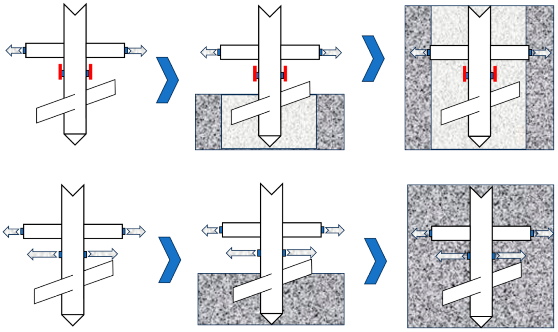
DMJ piles typically include four high-pressure nozzles—two at the drill pipe’s end and two on the mixing rod—controlled by dual high-pressure mud pumps. By adjusting the nozzle operation, the pile shape can be modified. As shown in
Figure 1, when all nozzles spray slurry, large-diameter solid DMJ piles (≈80 cm) are formed [
25]. Alternatively, when only the mixing rod nozzles operate, variable-modulus DMJ piles are created, featuring a high-strength exterior and a low-strength interior composed of returned slurry.
Due to the larger diameter of the pile formed by the DMJ pile composite foundation, the contact area between the pile and the surrounding soil is significantly increased. This, in turn, reduces the differential settlement between the pile and the soil [
26]. Compared to conventional small-diameter piles, DMJ piles offer superior bearing capacity and greater adaptability, thus providing more stable foundation support under embankment loading.
To investigate the bearing performance of DMJ group pile composite foundations, this study employs numerical simulation to compare foundation models with varying structural parameters. The analysis focuses on identifying the variation patterns of settlement behavior, pile–soil stress distribution, and pore water pressure within DMJ-supported systems.
2. Modeling of Composite Foundations
2.1. Geometric Parameters of Model
In this study, a roadbed project is selected for a detailed analysis using numerical simulation. The total width of the adopted roadbed is 28 m, with half of the roadbed width (14 m) selected for modeling due to symmetry. A roadbed height of 4 m is considered for this analysis. The slope ratio is set at 1:1.5, and to mitigate the boundary effect, the foundation dimensions are configured with a width of 60 m and a height of 30 m. A single row of piles is arranged, with the model width fixed at 1.8 m.
2.2. Material and Unit
The embankment fill is modeled using the Moore–Cullen (MC) model, an idealized elastic–plastic constitutive model that requires a minimal number of computational parameters, which can be derived from geotechnical tests on the foundation. The pile body material is represented by a linear elastic model, with the unit type for both the embankment fill and pile material being C3D8. For the foundation soil, the Modified Cambridge (MCC) model is employed. The Modified Cambridge model is widely recognized in the field of soil mechanics, especially for its application to normally consolidated and weakly over-consolidated clays. It incorporates key parameters such as hydrostatic pressure yield behavior, shear shrinkage, and compression stiffness, which are essential for geotechnical engineering analyses.
The study area is located within the Yellow River floodplain, in the lower reaches of the Yellow River Basin, characterized by a shallow groundwater table. The foundation soil is modeled as a surface layer of 1.5 m of coarse-grained soil, with the underlying soil saturated. The drainage surface is set at the water table, 1.5 m below the surface. The unit type for the surface coarse-grained soil is C3D8, while the unit type for the foundation soil involved in seepage is designated as C3D8P. To isolate the effects of pile type and minimize the interference from soil stratification, a homogeneous soil profile was assumed throughout the modeling process. This approach allows for a clearer identification of the pile type’s dominant role in governing bearing performance. The material parameters are provided in
Table 1. Among them, c represents cohesion; φ represents the friction angle; E represents Young’s modulus; ν represents Poisson’s ratio; λ represents the logarithmic bulk modulus for plasticity; κ represents the reciprocal of the bulk modulus; M represents the critical state stress ratio; e
1 represents the intercept of the virgin compression line; k represents the coefficient of permeability; and e
0 represents the initial void ratio.
Both tangential sliding and normal contact behaviors are considered to accurately simulate pile–soil interaction. For the tangential behavior, the Coulomb friction model is adopted, with a friction coefficient of 0.7. In terms of normal behavior, a “hard” contact model is used to prevent physical penetration between contacting surfaces. The small-sliding formulation is applied to capture potential micro-slip behavior realistically while maintaining numerical stability.
2.3. Load and Boundary Conditions
This study primarily focuses on the settlement behavior of the foundation after embankment filling, excluding the process of pile formation. The embankment is constructed in seven layers. The first layer consists of a 4% cement–soil cushion with a thickness of 0.4 m, while the remaining six layers are filled with embankment material, each layer having a thickness of 0.6 m. The filling duration for each layer is set to 5 days, with the settlement observation period extending over 300 days.
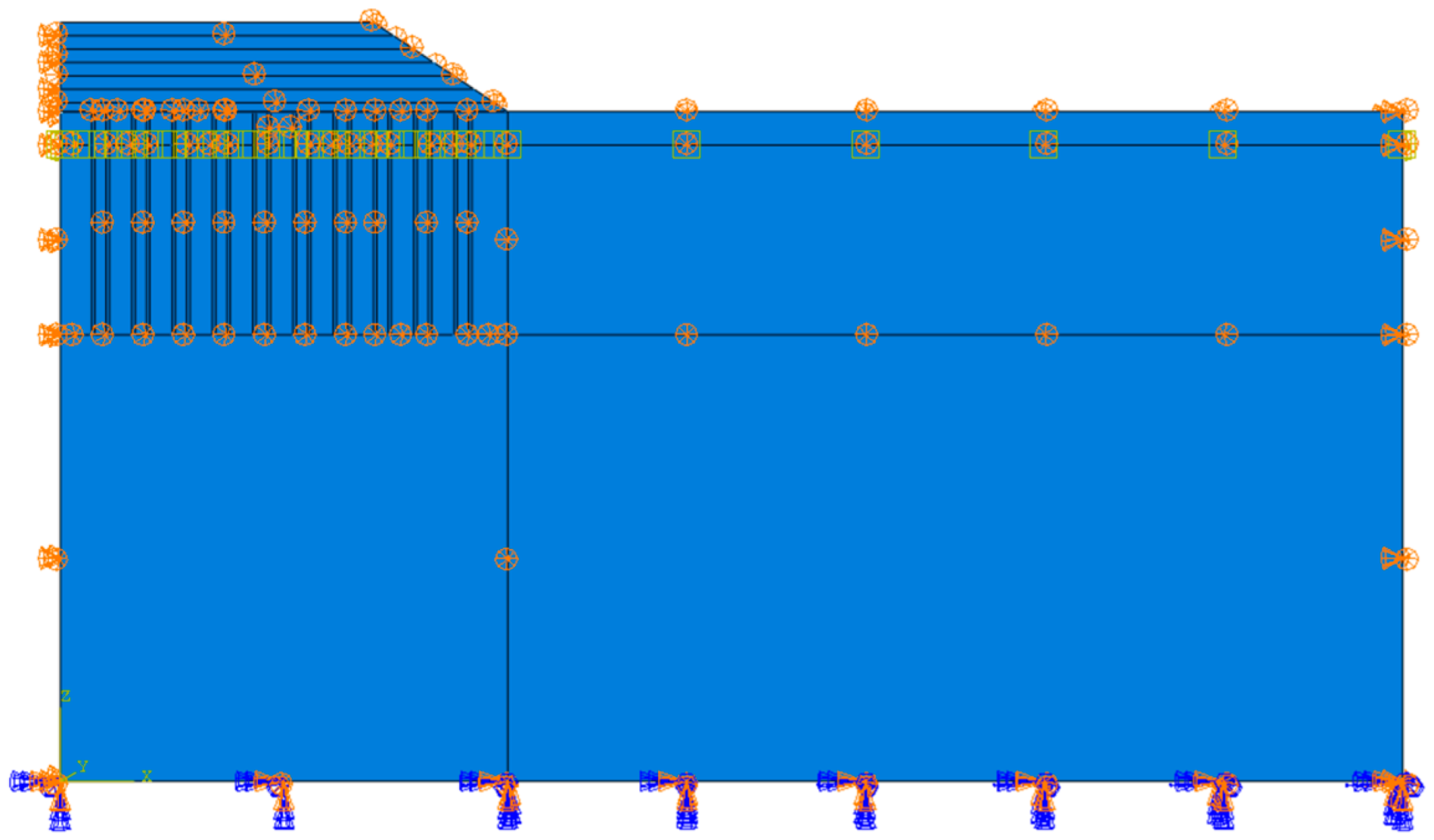
The numerical model is configured with a fixed boundary condition at the bottom, while radial movement at the sides is constrained. The boundary conditions of the model are set as shown in
Figure 2. The effective stress method is employed, with no specific material density defined. The self-weight of the material is incorporated through body forces. The self-weight above the water table is calculated using the natural weight, while the portion below the water table is accounted for using the effective weight.
2.4. Work Condition
A numerical simulation was conducted to examine the bearing characteristics of the composite foundation under two distinct conditions: equal pile spacing and equal area replacement rate. The working conditions are shown in
Table 2. In the simulation with equal pile spacing, the pile spacing was set at 1.8 m, and the piles were assigned serial numbers from FH-1 to FH-5.
For the equal area replacement rate scenario, an area replacement rate of 0.07, corresponding to a 0.5 m pile diameter and 1.8 m pile spacing, was used as the baseline for the back-calculations of DMJ piles. In this context, the pile spacing was adjusted to 2.8 m. For DMJ piles with a variable modulus, the area of the outer ring of the piles was used for calculations, with a pile spacing of 2.2 m.
3. Model Validation
To verify the reliability of the soil consolidation and settlement predictions using the ABAQUS numerical simulation method, this study references the numerical simulation conducted by Jiang [
27] on a PCC pile (Large-Diameter Pipe Pile by using Cast-in-place Concrete) composite foundation under embankment loading for model validation. The simulation is based on the field tests and 3D finite element analysis of a pile-supported reinforced embankment located in the northern suburbs of Shanghai, as reported by Liu et al. [
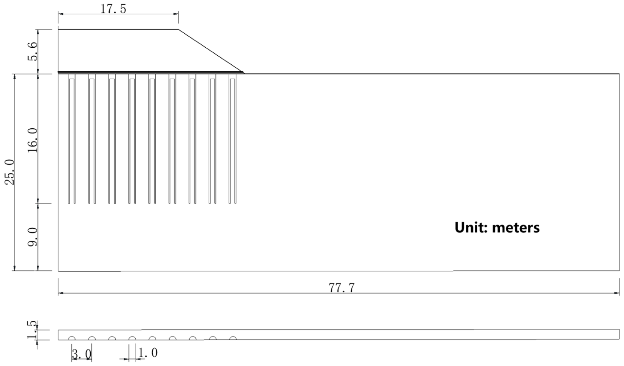
28]. This study provides detailed data and has been frequently cited in the literature. The constitutive model and modeling methodology adopted in this study are consistent with those used in the referenced work, making it suitable for model validation in the context of this research. The model sketch is shown in
Figure 3.
In this study, the original model was simplified to some extent for model validation purposes, aiming to enhance the efficiency of modeling and calculation. The original model section is reinforced with PCC piles, each with a length of 16.0 m, an outer diameter of 1 m, a wall thickness of 0.12 m, and a Young’s modulus of 20 GPa. For the purposes of this study, the PCC piles are approximated as a homogeneous linear elastic pile body with a modulus of 9 GPa. The piles are arranged in a square pattern with a spacing of 3 m.
The embankment features a top width of 35 m and a filling height of 5.6 m across nine layers, with the filling process completed in 55 days. The embankment’s side slope is designed at 1:1.5. Settlement observations were conducted 125 days after the completion of the embankment filling. The pile material is modeled as a linear elastic body, while the embankment fill, gravel bedding, and surface coarse-grained soil are modeled using the M-C model. The groundwater table is set at 1.5 m, and the soil model governing seepage is the MCC model.
Table 3 provides the soil and numerical modeling material parameters.
In this study, the results of the numerical simulation are compared with both the measured data and the simulated results from previous research, as shown in
Figure 4. This study conducts a comparative analysis of vertical settlement during the consolidation process, specifically examining four critical locations: the soil beneath the midpoint of the embankment, the pile head directly beneath this midpoint, the soil beneath the embankment shoulder, and the corresponding pile head beneath the shoulder.
The settlement values of both the soil and pile obtained in this study are found to be smaller than those simulated in the literature. This discrepancy is likely attributed to the simplification of the pile body as an equal-modulus pile in this study, which reduces the stress concentration on the pile side walls of the PCC piles. As a result, this simplification enhances the load-bearing capacity and improves the settlement control effect. The model validation results confirm the effectiveness of the modeling approach used in this study for accurately capturing the settlement characteristics of composite foundations under embankment loading.
4. Settlement Analysis
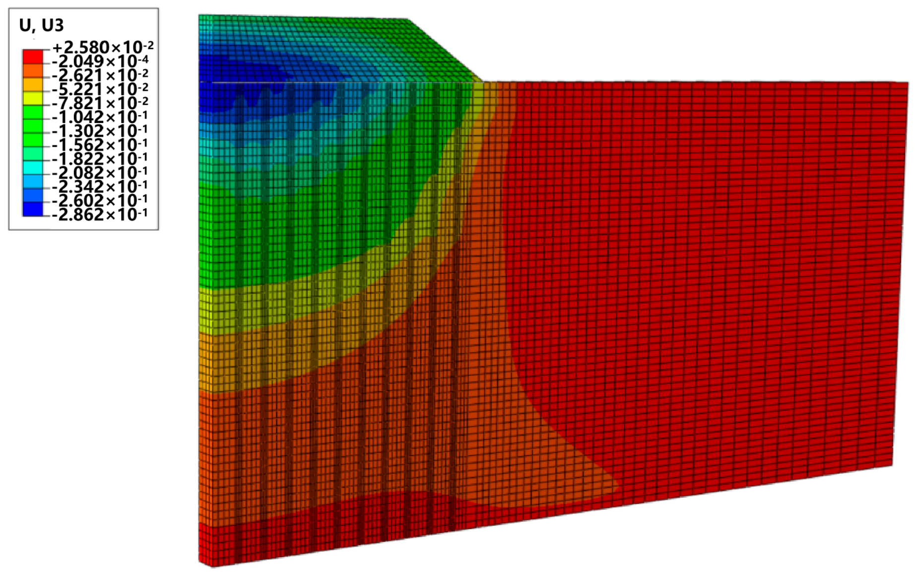
As shown in
Figure 5, the vertical displacement cloud after 300 days of consolidation is presented. The settlement of the foundation’s uppermost surface is dependent on the horizontal distance from the center of the embankment. The maximum settlement is observed at the base at the center of the embankment, with the settlement value gradually decreasing as the distance from the center increases.
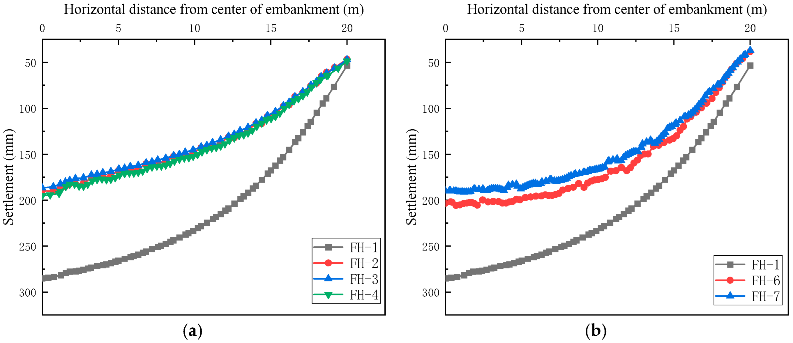
As illustrated in
Figure 6, the settlement of foundation soil is analyzed under conditions of equal pile spacing and an equal area replacement rate. It is observed that when the pile spacing is uniform, the maximum settlement of a conventional pile with a diameter of 0.5 m is 285 mm. The impact of modulus variation on the settlement of the DMJ pile foundation is found to be minimal, with the maximum settlements ranging from 185 to 195 mm. Increasing the diameter of the piles is shown to reduce the settlement of composite foundations by up to 35%.
When the replacement rate remains constant, the maximum settlement of FH-6 is 203 mm, and that of FH-7 is 190 mm, representing a reduction of 28.7% and 33.3%, respectively, compared to conventional piles. The increase in settlement value is minimal compared to the case with equal pile spacing. Additionally, when an equal replacement ratio is used, the number of piles per unit area decreases by 49% and 142%, respectively, in comparison to conventional piles. This reduction in pile quantity can significantly enhance construction efficiency in real-world applications.
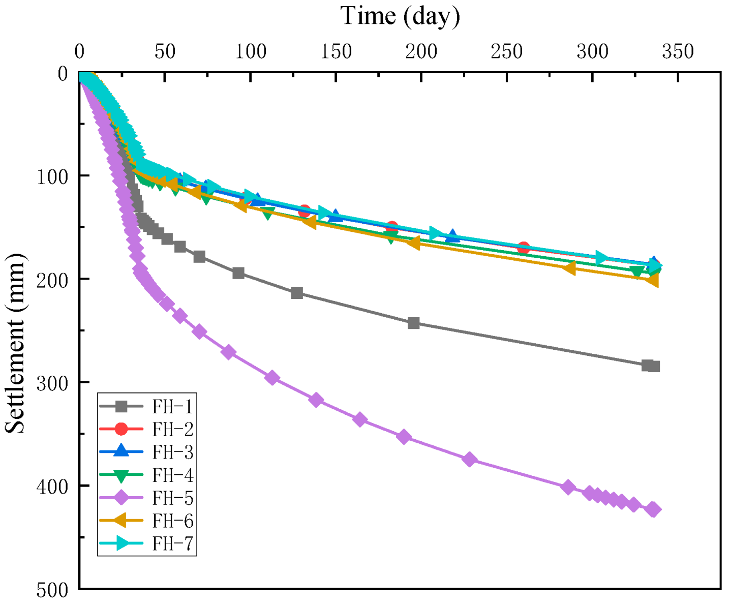
Figure 7 illustrates the settlement of the topsoil of the foundation beneath the center of the embankment as a function of time. During the filling stage, the foundation settlement increases rapidly. Once the filling process is completed, the foundation soil undergoes gradual consolidation, and the settlement rate slows down. Among the various foundation types, the consolidation settlement of the natural foundation soil occurs the fastest, with a maximum settlement of 423 mm. In contrast, the composite foundation reduces the rate of settlement development. The rate of settlement development for the DMJ pile composite foundation is significantly slower compared to that of the conventional pile composite foundation. Furthermore, the controlled settlement rates of the DMJ piles at different pile spacings show minimal variation.
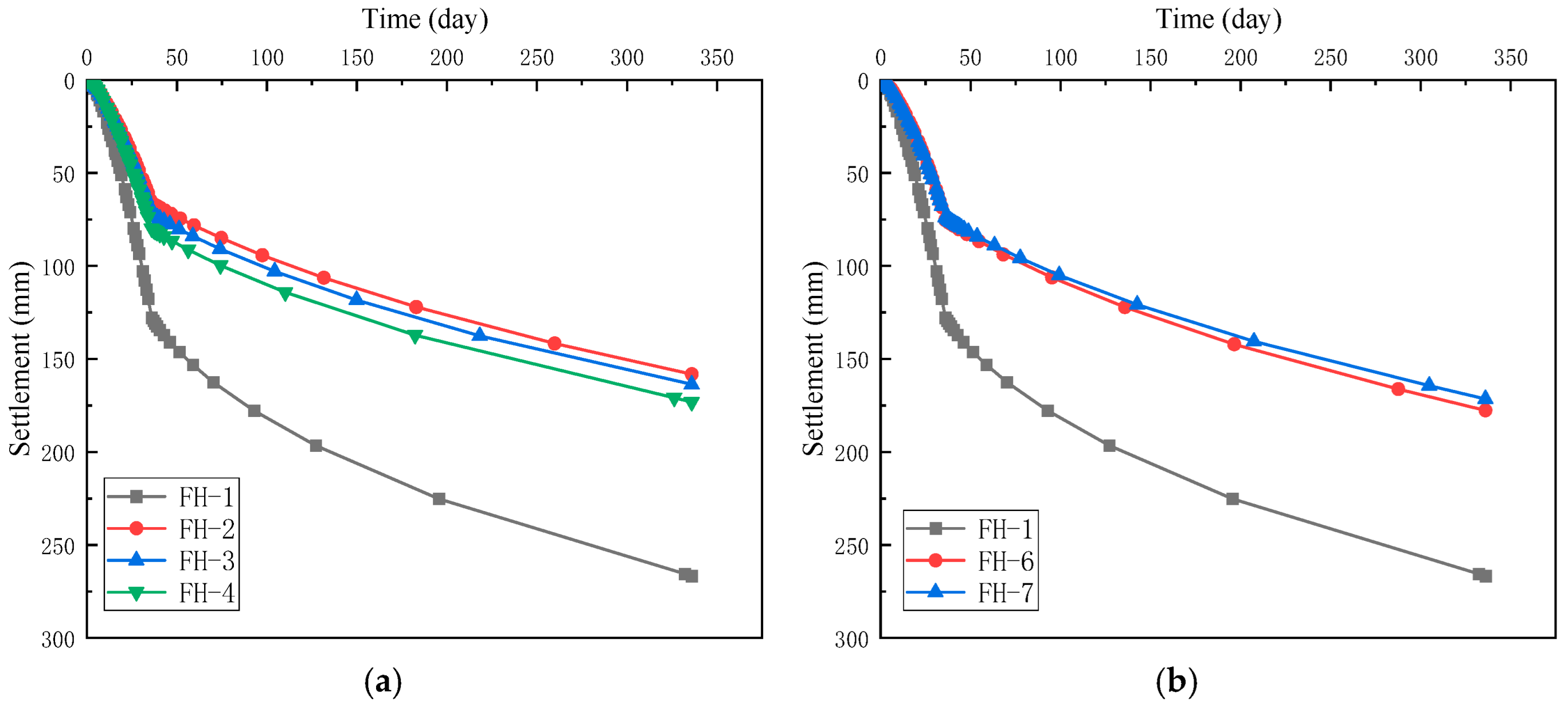
Figure 8 illustrates the change in the pile top settlement over time for the pile located at the center bottom of the embankment. The final settlement of conventional piles is 266 mm when the pile spacing is 1.8 m. The settlements of FH-2 and FH-3 are 158 mm and 163 mm, respectively. It is observed that the pile top settlement increases as the pile core modulus decreases. The settlement of the capped pile, FH-4, is 173 mm, and the smaller modulus at the pile side results in a settlement greater than that of the DMJ piles and variable-modulus DMJ piles. For the equal area replacement rate scenario, the pile top settlements of FH-6 and FH-7 are 171 mm and 177 mm, respectively. This increase in settlement is attributed to the larger pile spacing of the DMJ composite piles.
The distribution of horizontal displacement with depth at the toe of the embankment slope, measured 300 days after the consolidation of the foundation soil, is shown in
Figure 9. The maximum horizontal displacement of the conventional pile composite foundation is 62.7 mm, occurring at a depth of 2 m from the top of the foundation soil. For the DMJ pile composite foundation, the maximum horizontal displacement occurs at 10.5 m from the surface.
For the equal pile spacing condition, the maximum horizontal displacement of the foundation soil is 45 mm for FH-2 and FH-3 and 46.1 mm for FH-4. Under the equal area replacement ratio scenario, the maximum horizontal displacement of 46 mm for FH-6 is slightly smaller than the 47.8 mm displacement for FH-7, due to the smaller pile spacing in FH-6. This suggests that the smaller pile spacing helps transfer the horizontal displacement generated by the overlying embankment to a relatively deeper location, resulting in a smaller displacement value.
5. Pile and Soil Stresses
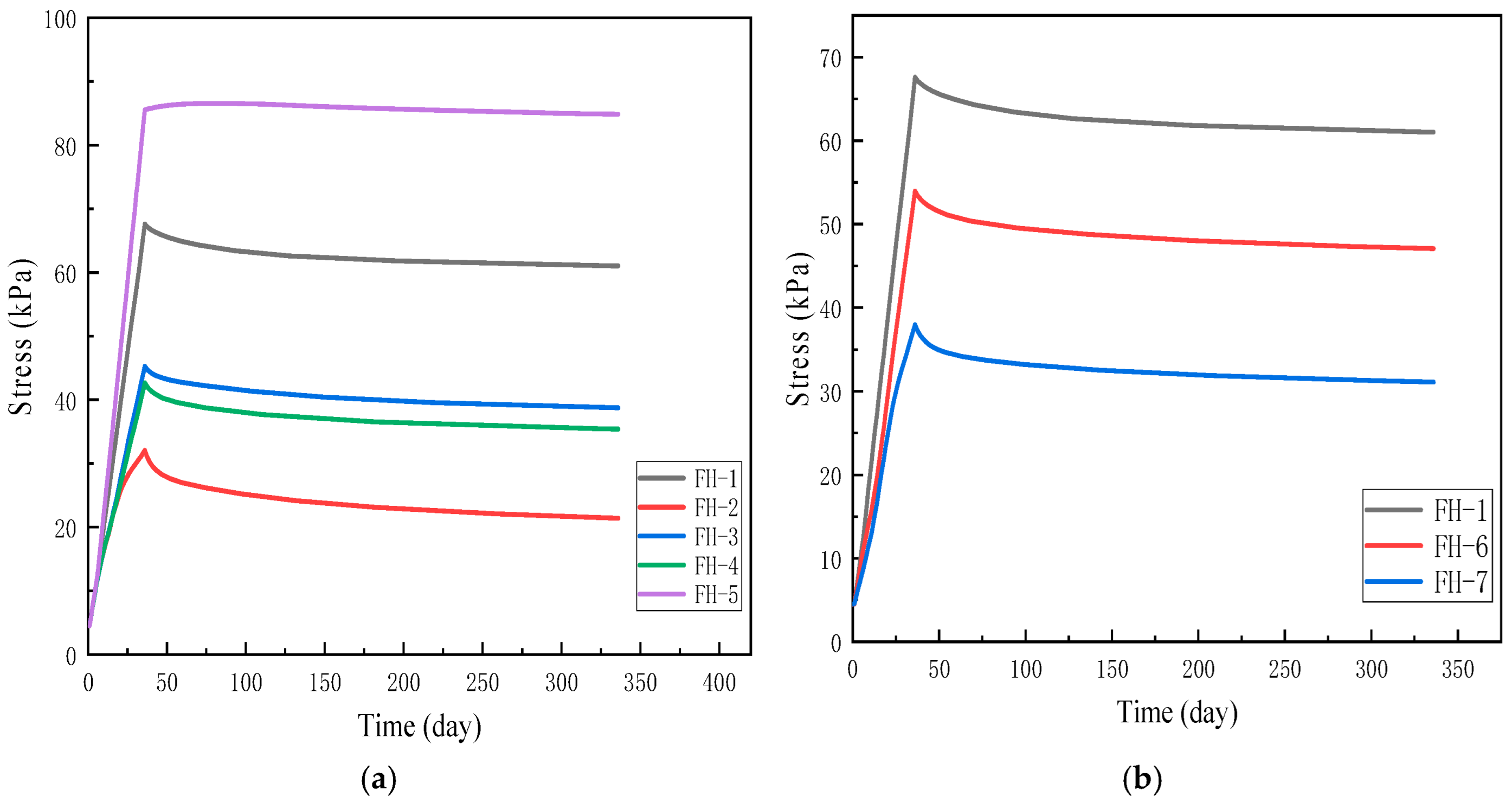
The variation in inter-pile soil stresses at the top of the foundation beneath the midpoint of the embankment over time is shown in
Figure 10. As the filling process progresses, the stress on the top surface of the foundation soil gradually increases, reaching a peak on day 35, the end of the filling period, and then decreases slowly to a stable level. The stress borne by the top surface of the foundation soil stabilizes at 84 kPa for the FH-5 condition (natural soil beneath the embankment). After the piles are placed, the stress borne by the foundation soil decreases, with most of the loads being transferred to the piles.
For the conventional pile condition, the stress in the soil between piles stabilizes at 61 kPa, while for the FH-2, FH-3, and FH-4 conditions, the stresses in the inter-pile soil stabilize at 21.4 kPa, 38.7 kPa, and 35.4 kPa, respectively. This reduction is due to the higher strength of the DMJ piles at the top, which share more of the load from the foundation soil. The proportion of the load borne by the variable-modulus DMJ piles is smaller due to the lower modulus of the pile cores.
For the equal area replacement ratio scenario, the pile spacing of FH-6 is larger than that of FH-7, causing more of the load to be carried by the inter-pile soil. The inter-pile soil stress stabilizes at 47 kPa for FH-6, while for FH-7, the inter-pile soil stress stabilizes at 31 kPa.
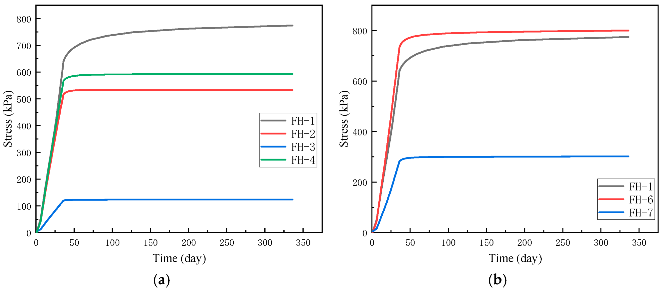
The stresses at the center of the pile beneath the center point of the embankment are shown in
Figure 11. As the filling process progresses, the stress at the top of the pile increases rapidly and levels off once the filling is complete. The maximum stress at the top of the pile is 774 kPa for the conventional pile, which can be attributed to its smaller pile diameter.
For DMJ pile FH-2, the stress at the center of the pile top decreases significantly due to the increased pile diameter, stabilizing at 533 kPa. For variable-modulus DMJ pile FH-3, the stress at the center of the pile top is even lower due to the lower modulus of the pile core, reaching 124 kPa. The pile center is subjected to a smaller proportion of the load, and none of the overburden loads significantly affect the pile body. This explains why the settlement control effects of FH-2 and FH-3 are similar. For FH-4, due to the lower strength of the pile body, the top of the pile bears a larger proportion of the load, and the stress at the center of the pile is 593 kPa.
When the area replacement ratio is the same, FH-6, with the largest pile spacing, exhibits the highest proportion of load carried by the pile body. The stress in the center of the pile is higher than that of conventional piles and much higher than that of the variable-modulus DMJ piles, reaching 800 kPa. This highlights the importance of having a higher-strength pile body to effectively manage the increased load.
6. Pore Water Pressure
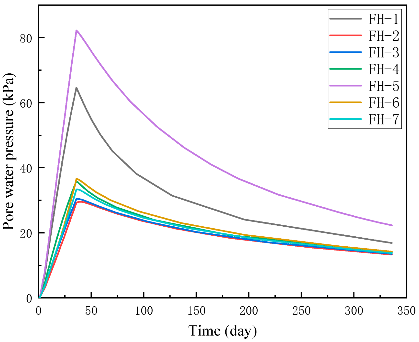
To compare the pore water pressure dissipation under different working conditions, the pore water pressure data were analyzed for various pile types and pile spacing configurations. The change in pore water pressure with time at a depth of 5 m is shown in
Figure 12. During the filling process, the pore water pressure increases rapidly and gradually decreases with the drainage and consolidation of the soil at the end of filling. The maximum pore water pressure in pure soil at 5 m is 82 kPa, while the maximum pore water pressure in the traditional pile composite foundation at this location is 64.6 kPa, which is 21% lower than that of pure soil. In the pile–soil composite foundation, the pile body bears most of the load, reducing the stress on the soil body and thus lowering the pore water pressure in the soil.
In the DMJ pile composite foundation, the pore water pressure in the soil of FH-2 and FH-3 is the smallest. This is due to the 1.8 m pile spacing in these two conditions, along with the higher relative strength of the pile body. As a result, the soil body bears a smaller proportion of the load, and the increase in pore water pressure due to the load is minimal. In contrast, for FH-4, the lower strength of the pile body leads to a larger proportion of the load being borne by the soil between the piles, resulting in a higher corresponding pore water pressure of 35.6 kPa.
For the equal area replacement ratio case, FH-6 and FH-7, which feature higher-strength DMJ piles, have a relatively lower proportion of the load borne by the soil between the piles. The peak pore water pressure in the pile body is slightly lower than that of the variable-modulus piles, with a pore water pressure of 33.3 kPa and 36.5 kPa in the inter-pile soil for DMJ piles.
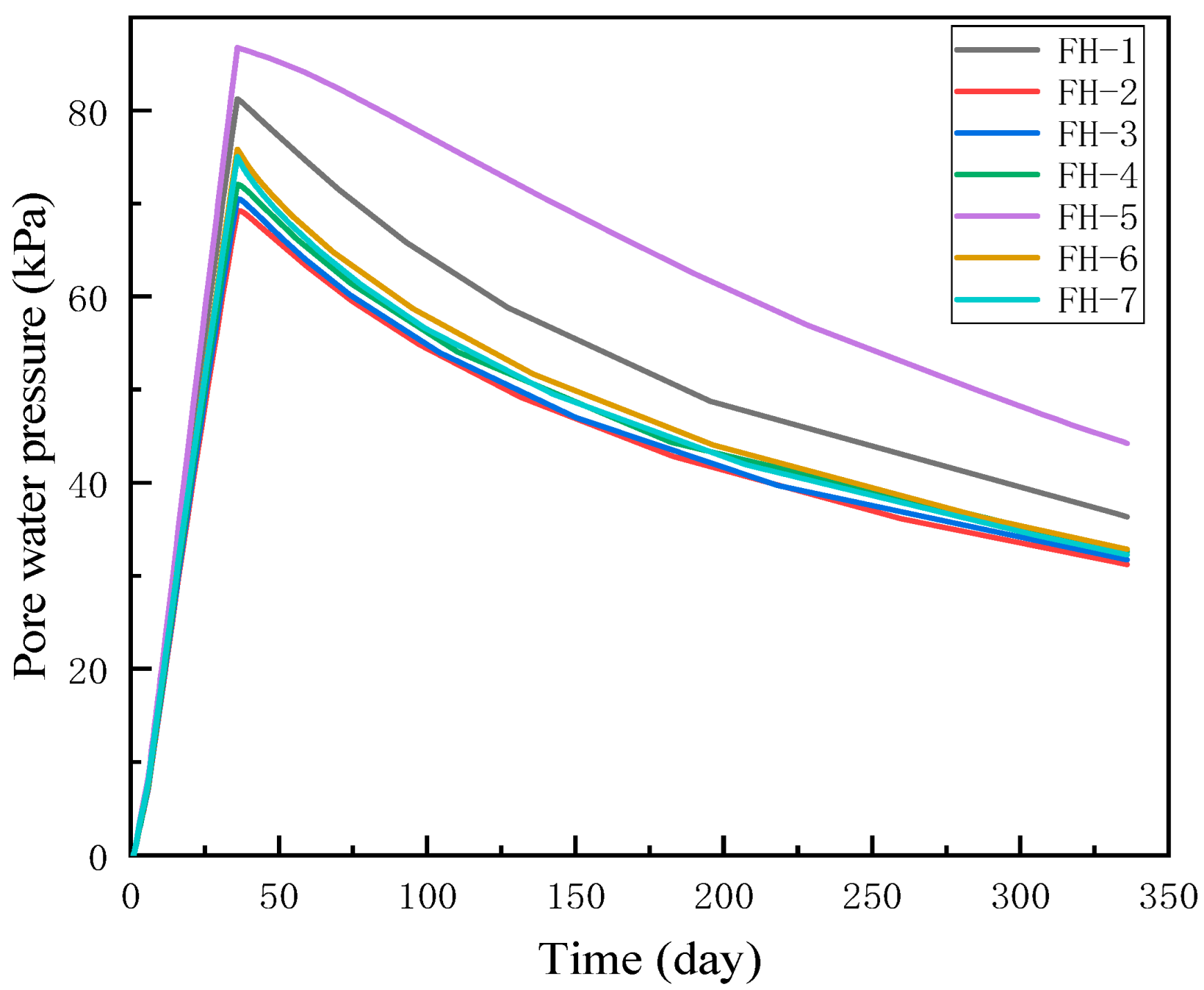
The variation in pore water pressure in the soil between piles at a depth of 10 m is shown in
Figure 13. The peak pore water pressure in pure soil is 86.7 kPa, which represents only a 5.7% increase compared to the peak pore water pressure at 5 m, indicating that embankment loading had little effect on the pore water pressure in the depth range of 5–10 m. The peak pore water pressure for the traditional pile composite foundation is 81 kPa, which is 25% higher than that at the 5 m depth.
In the DMJ pile composite foundation, the pore water pressure increases significantly with depth, with the increase rate surpassing 100%. The difference in peak pore water pressure between different pile types becomes smaller as depth increases. This indicates that DMJ piles are more efficient at transferring the load to deeper soil layers, thereby fully utilizing the bearing capacity of the soil at greater depths. This behavior is consistent with the results from settlement analysis, which show that DMJ piles can effectively transfer the embankment load to deeper foundation soil.
An increase in the diameter of DMJ piles significantly enlarges the pile–soil contact area, thereby enhancing the inter-facial shear strength and load transfer efficiency between the pile and the surrounding soil. The enlarged diameter contributes to an improved load-bearing capacity of the pile, particularly by facilitating the mobilization of both side resistance and end bearing. Moreover, the larger diameter enables them to carry a greater proportion of the applied load, effectively transmitting it through the upper weak soil strata to deeper, more competent soil layers.
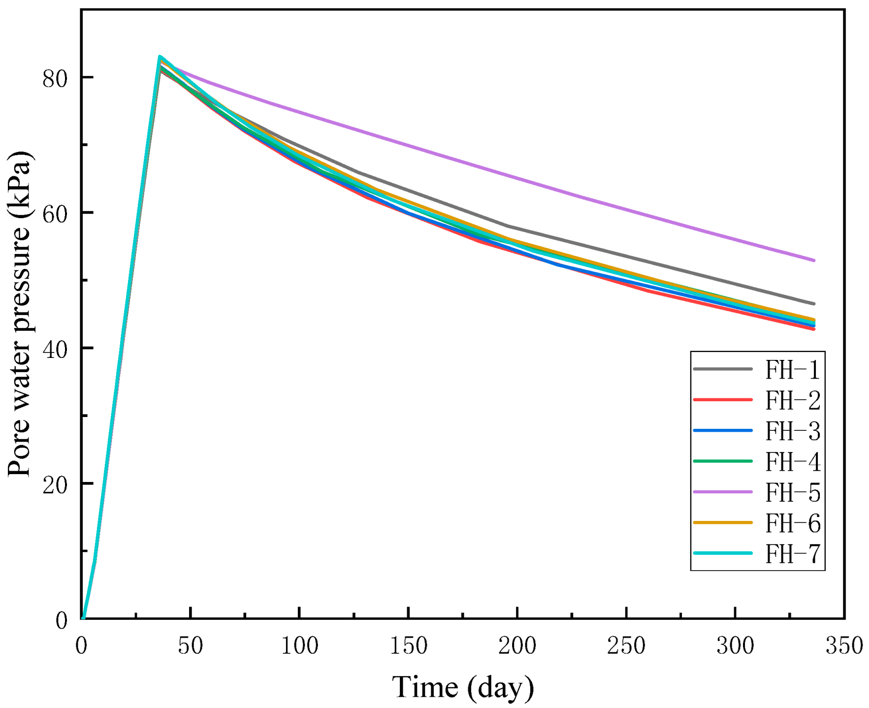
The change in pore water pressure at a depth of 15 m is shown in
Figure 14. The peak pore water pressure of the foundation soil in the DMJ pile composite foundation is 82 kPa, while the peak pore water pressure of the foundation soil in both the pure land and traditional pile composite foundations is 80 kPa. These values are slightly lower compared to those at a depth of 10 m, indicating that the embankment loading on the soil between the piles at the 15 m depth is relatively small. Moreover, the ultimate pore water pressure in the soil between the piles decreases as the depth continues to increase.
The peak pore water pressure and the trend in pore water pressure change in the DMJ pile composite foundation at the 15 m depth are almost identical. The peak pore water pressure increases to 83 kPa, representing an increase of 10.6% to 20% compared to the pore water pressure at the 10 m depth. This suggests that the overburden loads can still be transferred to a depth of 15 m, affecting the change in the pore water pressure of the foundation soil. These results further demonstrate that the load transfer depth of DMJ piles is larger, highlighting their capability to transmit load to deeper soil layers.
7. Conclusions
This study investigates the bearing characteristics of DMJ composite pile group foundations under embankment loading using ABAQUS numerical simulation. By analyzing the effects of different pile types and pile spacing, the following key conclusions are drawn:
- (1)
The DMJ pile composite foundation demonstrates significantly superior performance in controlling settlement compared to conventional piles under conditions of equal pile spacing and an equal area replacement ratio, with the pile core modulus having a relatively minor effect on settlement control.
- (2)
The DMJ piles are capable of bearing the majority of the embankment load, thereby reducing the bearing pressure exerted on the soil between the piles and effectively transferring the load to deeper soil strata.
- (3)
In comparison to composite foundations utilizing conventional piles, DMJ pile composite foundations can transfer loads to a depth of up to 15 m within the foundation soil, whereas conventional pile composite foundations are limited to a depth of 10 m.
- (4)
Under the same pile spacing, an increase in pile diameter leads to a marked reduction in settlement, and the settlement control performance of variable-modulus DMJ piles proves to be particularly effective.
- (5)
Pore water pressure analysis further reveals that the DMJ pile composite foundation effectively mitigates the accumulation of pore water pressure in the soil, thereby enhancing the stability and deformation resistance of the foundation.


