Abstract
Automation is revolutionizing a number of sectors, including construction, by bringing about important technological breakthroughs that increase productivity and efficiency. Automation in safety procedures is still scarce though. In India, the majority of safety procedures are still reactive, manual, and paper-based. This study is a component of a broader research project on automated safety screening for fall risks enabled by BIM. It entails codification of OSHA rules to perform safety checks, placing corrective actions into location, and generating reports in a virtual environment. As part of the broader risk lifecycle, these tasks are typically completed on-site during the various stages of construction. This study, on the other hand, executes these steps in a virtual environment in the preconstruction phase. The model has been assessed in a pilot study in India and was developed especially to address fall hazards from staircases. Through early hazard identification and mitigation, the system assists professionals in enhancing overall safety performance.
1. Introduction
The construction industry is one of the highly recognized and valuable sectors across the globe. It is the primary source of economic development for any country. With Industry 4.0, the focus of the construction sector is shifting from conventional practices to intelligent construction management solutions. The journey to adopt digital technologies to perform construction activities is not new but is gaining traction because of technological advancements. Starting from paper-based design drawings to using CAD and moving to computerized simulated models shows the paradigm shift of the construction process. It encompasses a wide range of projects, covering the construction of residential buildings, commercial complexes, roads, bridges, dams, airports, and other infrastructure projects. These processes involve meticulous planning, design, engineering, procurement, and execution to ensure the successful completion of projects. Due to an increase in high-rise building complexes, involvement of multiple construction activities, use of heavy machinery, and the increased need to work at heights, the provision of safe work environments becomes a de facto requirement for most construction sites. Failure to provide safe work environments has negative implications for the industry and its workforce.
India’s construction sector is the second largest employment generator, with a 7.1 crore workforce employed currently [1]. The cost spent on labour is 30% to 50% of the total project costs [2]. India is a labour-oriented industry, so the management of the human workforce and the provision of a safe work environment are of primary importance as poor safety practices usually result in injuries or fatalities [3]. One in ten construction workers sustain an injury annually, according to the Occupational Safety and Health Administration’s (OSHA) recommendations. According to OSHA, globally, the leading cause of injuries on construction sites is likewise falling hazards [4]. According to the International Labour Organization (ILO), 60,000 fatal construction accidents occur globally each year—one every 10 min [5]. In Great Britain, 123 workers died in work-related accidents in 2021/22, down from 145 in 2020/21 [6]. Given the increased number of construction accidents, safety management requires more attention. The primary goal for any site safety program is the need to provide safe working environments that reduce the risks of injury, avoid unnecessary delays, result in timely completion of projects, and lead to improved productivity. Also, the current building design presents volume, complexity, and multidisciplinary integration, which by the traditional method based on drawing, becomes difficult to manage in time and in control of costs [7]. Numerous approaches could be adopted to fulfill this need. With the advent of technology and the need for efficient and time-bound construction, modern construction methods and equipment have gained prominence. Automation and robotics, artificial intelligence (AI) [8], building information modeling (BIM), virtual reality (VR), augmented reality (AR), and 3D printing [9] are few technologies that are examples.
The present study is a component of a broader umbrella of research on automated safety checking for fall hazards that are enabled using BIM. The developing countries like India have negligible studies in the field of safety management using BIM [10]. Unlike the BIM mandate and BIM handbooks in different countries, the majority of their construction processes are executed using BIM, whereas implementation of BIM in India is limited to design and drawing purposes only [11]. Most of the studies are limited to identifying barriers to adopting BIM rather than its actual implementation in practice. Also, the available research focuses on one particular case of fall, though there are other causes, too. The research presented in this paper aims on developing the model for fall hazards caused by the faulty staircase in the building. Staircase safety is a critical aspect of construction site management to protect workers and occupants from injuries. A retrospective analysis conducted at the All India Institute of Medical Sciences in New Delhi examined 92 cases of deaths resulting from accidental falls down staircases over a decade (1996–2005). The study offers a complete package of site safety management, including hazard identification, safety checking with standard interpreted rules, required safety equipment, and safety reports. The model performs a safety check for the entire construction project from inception (early design) through construction to completion in the virtual environment.
The different staircase hazards include falls due to a lack of handrails or incomplete staircases, uneven risers and treads, neglecting Personal Protective Equipment (PPE) such as non-slip boots, and wet or greasy surfaces. These hazards can be minimized if they are managed in advance, prior to construction. Additionally, designing a staircase in a construction project requires careful consideration of functionality, safety, aesthetics, and structural integrity. This study focuses on preventing staircase hazards through designs and choosing which fall prevention system to use, where to install it, and when. The outputs that can then be represented in BIM as safety rules from standard safety regulations are interpreted and utilized to check the design model in the early project stages.
2. Literature Review
It is critical to examine and understand existing site safety management processes in order to determine the opportunities for automated BIM-based site safety management. One of the most important considerations in any construction work is safety. In construction project management, safety planning is essential because it helps prevent needless expenses and delays brought on by unintentional mishaps [12]. Essential components of safety management include identifying all safety hazards and assessing the risk associated with each hazard. There are no definitive guidelines for identifying, discussing, and managing health and safety hazards at work. Nonetheless, there are a few broad guidelines that ought to be adhered to. The majority of risk management approaches adhere to the same fundamental ideas, regardless of differences in approaches or industries. ISO 31000 states that the primary steps of a typical conventional site safety management are context-setting, hazard identification, risk analysis, risk evaluation, and risk treatment. These components mainly take place in the physical environment [13].
In India, the vast majority of safety management procedures are paper-based for most construction activities. Safety planning is done by manual observations, which are labour-intensive and prone to inaccuracy. There are insufficient processes in place for identifying the risk-prone areas before construction begins [11]. The identification and prevention of safety hazards in traditional safety planning is done manually [14,15,16]. This approach relies upon the expertise and experience of the safety planner and is labour-intensive, time-consuming, ineffective, and prone to mistakes [11]. As the construction industry grows rapidly, the quantum of work increases, and the probability of risks also increases. The solution must be both robust and effective in mitigating risks. Implementing advanced safety techniques in construction processes is the best approach to achieving this goal.
BIM is a platform for collaboration used by the Architectural, Engineering, and Construction (AEC) sectors that is based on several software options [17,18]. BIM is defined as a systematic process for managing and disseminating holistic information generated throughout the development and operation of building design [17]. Relevant studies from the past decade were gathered from the Scopus database using defined keywords (BIM, Safety, Construction). There are a total of 1173 documents related to BIM for safety globally, and out of these, 28 are from India (data accessed on 6 May 2025). Out of these retrieved articles, the most relevant were ultimately chosen for review.
The potential applications of BIM span over the entire project lifecycle [11]. There are multiple benefits of BIM and they are not limited to modeling, scheduling, cost, facility management, energy management, information storage and sharing, and safety management. Figure 1 illustrates the lifecycle applications of BIM over a construction project. However, these benefits are not fully explored in Indian construction firms [11].
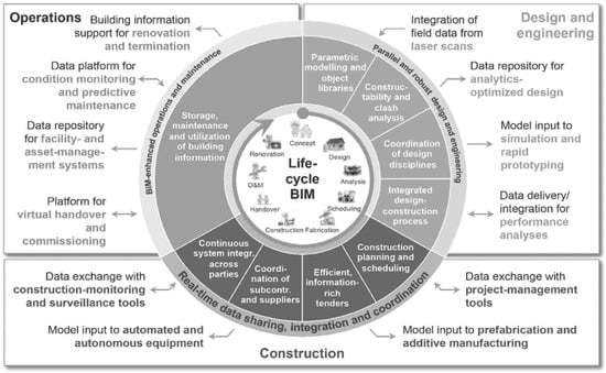
Figure 1.
BIM applications across the value chain for engineering and construction (Source: https://www.bcg.com/publications/2016/engineered-products-infrastructure-digital-transformative-power-building-information-modeling, accessed on 16 May 2025).
Moreover, BIM allows the integration with other emerging technologies like Geographical Information Systems (GIS) [19], Unmanned Arial Vehicle (UAV) [20], GPS [21], Radio Frequency Identification [22], and ultra-wide bands (UWB) [23]. The application of all these technologies integrated with BIM is studied by various researchers. The summary is presented in Table 1 below.

Table 1.
Integrated BIM approach and application for site safety.
Most of these technologies have been designed to provide safety solutions primarily for the construction stage. However, the application of technology for construction safety needs to be extended beyond the construction phase to include the pre-construction and maintenance phases as well. Additionally, many of these technological advancements have been confined to academic research with limited implementation in actual construction safety management. The focus should now shift towards transitioning these technologies from research into practical application. BIM-based safety management systems can leverage a buildable design theory, preventing and managing risks found in the BIM as well as using the Construction Safety Audit Scoring System to determine productivity and safety indices [28]. The 3D logistics plans are also very useful to minimize the safety and health risk at the construction site as the 3D plans provide more clarity in the proposed logistics approaches that are normally difficult to display on a 2D plan [29]. Another prominent application of BIM for safety is the integration of 3D models with automated safety rules for automated safety checking. The primary objective of rule checking is to check project designs for hazards and automate these safety regulations. In order to automate safety rules, they must be transformed into a machine-readable format. Although this is not directly supported by current BIM enabled softwares, it can be accomplished by combining BIM platforms with rule-checking platforms or those that can read building models, such as Navisworks or IFC platforms, or by introducing a plugin to programs like Revit [30]. Each method of integration has its pros and cons. Using a plug-in can be the simplest because it works within existing software like commercial BIM authoring tools, some of which have their own programming interface called an API. However, the downside is that it is limited to one specific BIM software and may have issues with data compatibility, restricting it to only certain types of BIM models. Additionally, the programming capabilities of the integrated tool may be limited [31]. Different systems used to check and enforce rules, including ePlanCheck, FORNAX [32], Semantic Web [33], KBIM [34], and Natural Language Processing (NLP) [35], are available. One widely used commercial program is Solibri Model Checker, now replaced by Solibri Office [36]. This program can import models from different BIM software and virtually analyze safety rules and hazards during the design phase. This study applies the conceptual framework (Figure 2) developed by [36] which is to check the safety checking of the staircase hazards case.
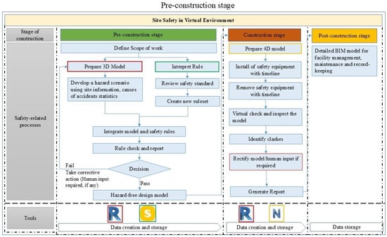
Figure 2.
Conceptual framework for automated safety checking with process enablers such as ‘R’ representing Autodesk Revit, ‘S’ representing Solibri Office, and ‘N’ representing Navisworks [36].
The framework is validated in this study throughout the preconstruction phase, which primarily entails automated safety checking of the model in order to ensure a design free of hazards. Furthermore, the case of the faulty staircase is designed including three different scenarios: I. Missing handrails, II. Inadequate tread and riser, and III. Inadequate size of handrail. The associated safety rules are interpreted, and safety checking is performed to identify the hazards using the interpreted rule. This process includes verifying that the OSHA safety protocols, such as handrail installation, are correctly integrated into the design before construction begins. The results of this validation are illustrated below, showcasing the effectiveness of the proposed framework in identifying and mitigating potential hazards related to faulty staircases during construction.
3. Model Development for Staircase Hazards
The present study is a component of broader research that focuses on the automation of the safety checking process with the BIM approach. This study was initiated by conducting an overview of current safety practices and identifying the most common causes of accidents on construction sites. The method of automatic safety checking involves various steps. To understand the flow of each step, a framework is developed. The model is developed and validated on a sample project per the designed steps. This proposed system automates existing safety rules from OSHA guidelines, codifies safety experts’ knowledge, and tests it on a BIM. To perform the process of automated safety checking, several steps need to be performed sequentially as shown in Figure 3. Before initiating the main process of automatic safety checking in the research, some preliminary studies need to be conducted. These include identifying the hazard cases where safety checking needs to be performed. This study developed scenarios in 3D modeling environments in which the common causes of staircase falls are considered (e.g., missing handrails), the rules are interpreted and applied (e.g., staircase must have handrails), and safety checks are performed to verify that the safety requirements are met (Figure 3).
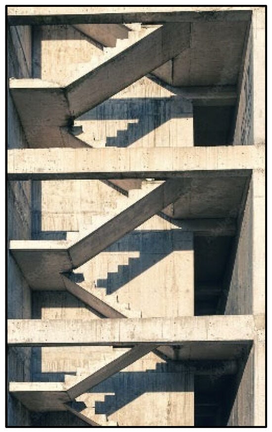
Figure 3.
Missing handrails on staircase [Source: https://www.alamy.com/stock-photo/concrete-stairsconstruction.html?sortBy=relevant, (accessed on 3 January 2025)].
Through a review of different construction hazards, the most common causes were understood. Falls are a major cause of accidents and occur on site. Considering this, the hazard scenario of the faculty staircase that leads to fall hazards is designed for performing the safety checking in this study.
On construction sites, staircases are frequently used as walking surfaces both during construction and during the entire construction process. They also act as channels for the transfer of materials between floors. Falls on stairs, however, have the potential to cause fatalities or serious injuries [37]. Figure 3 illustrates the photographs of the staircase without handrails.
There are different scenarios in the case of staircase falls. In this study, the three most common scenarios considered were missing handrails (Scenario I), inadequate dimensions of tread and riser (Scenario II), and inadequate height of handrails (Scenario III). To facilitate this BIM-enabled automated safety checking in construction, some process enablers are used. These process enablers are Autodesk Revit version 2020 and Solibri Office version 9.13.0.23. The 3D model is prepared in Revit. For rule checking and rule interpretation, Solibri Office is used. For each scenario, all the steps of automated safety checking are performed and presented below.
3.1. Three-Dimensional Model Creation (Scenarios I and II)
For Scenarios I and II, a sample 3D model of a staircase without handrails was designed in Revit (Figure 4). The tread and riser of the staircase was designed without proper dimensions to check whether the created rule identifies this error or not.
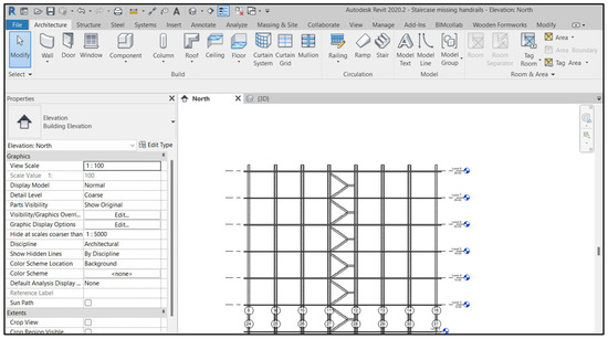
Figure 4.
A 3D model of a staircase without handrails (Scenario I) and incorrect tread dimensions (Scenario II) created in Revit.
3.2. Rule Interpretation (Scenarios I and II)
For both scenarios, the associated safety requirements and rules were reviewed from OSHA standards. As per OSHA 1926.1052(c)(1), Stairways having four or more risers or rising more than 30 inches (76 cm), whichever is less, shall be equipped with: 1926.1052(c)(1)(i) At least one handrail; and 1926.1052(c)(1)(ii) One stair rail system along each unprotected side or edge. For the riser and tread, the maximum riser should be 240 mm, and the minimum tread should be 240 mm [38]. All the standard dimensions are adopted from the OSHA rule book, and a new rule set is created in Solibri Office. This textual rule is considered while interpreting and converted into parametric format. Figure 5 and Figure 6 represent the rule interpretation for Rule I and Rule II.

Figure 5.
Safety rule interpretation in Solibri Office for Rule I.

Figure 6.
Safety rule interpretation in Solibri Office for Rule II.
- Rule I: The stairs must be supported with handrails.
- Rule II: Tread and riser dimensions.
3.3. Rule Integration (Scenarios I and II)
For integration, the 3D model is converted into IFC format for exchanging the file into rule-checking software, i.e., Solibri Office. The converted file is opened; however, the rule-checking tab will not be visible unless the 3D model is opened in Solibri’s workspace. In the rule integration process, each of the building components is read through, and its information is obtained on the rule-checking platform. For example, there are multiple slabs in the model; each slab has a unique identity and parametric information, including name, type, and material associated with it. With this information, the exact component and location of the hazard can be detected. The converted file is opened in an interpreted platform (Figure 7).
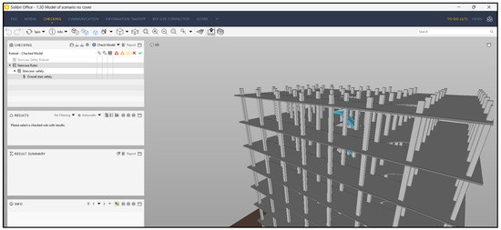
Figure 7.
Integrated model view of Scenarios I and II in Solibri Office highlighting staircase in model.
3.4. Rule Checking and Hazard Identification
Once the model is integrated into Solibri, Rules I and II are set up by the rule set manager to check the model. By using the checking tab, the model is run, and results are obtained. The results show identified issues representing the staircase with missing handrails and inappropriate dimensions of the tread. The rules are successfully run, and the hazards are identified (Figure 8 and Figure 9).
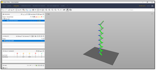
Figure 8.
Rule checking and hazard identification for Scenario I highlighting the missing handrails on stairs and landings.
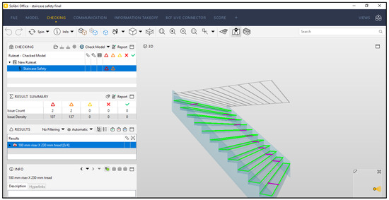
Figure 9.
Rule checking and hazard identification for Scenario II highlighting the inappropriate trade dimension.
3.5. Reporting (Scenarios I and II)
A report of identified issues is auto-generated with the details of the location of the possible occurrence of the hazard, enabling the preparation of a corrective action plan. Figure 10 illustrates the report generated for Scenarios I and II.
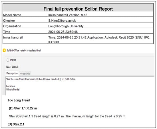
Figure 10.
Generated report of identified hazards for Scenarios I and II.
3.6. Corrective Actions (Scenarios I and II)
In this step, the 3D model is updated by providing the handrail on the stairs, and the dimensions of the tread are changed as per the report as part of corrective actions. All the corrective actions are manually designed in Revit. Figure 11 represents the addition of the handrails and the updated dimensions of the tread in Revit.
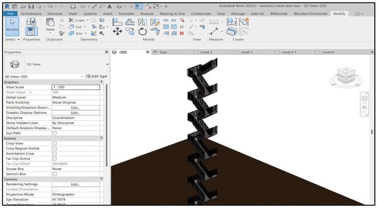
Figure 11.
Corrective actions taken for Scenarios I and II in 3D model of Revit.
3.7. Rechecking and Reporting (Scenarios I and II)
Once again, the model is integrated with the checking platform, and the model is checked for accuracy in the design to avoid accidents. Figure 12 shows the rechecking of the model with corrective actions. It shows that the rule is successfully passed as handrails are provided on the stairs, and the dimensions of the tread are as per the rule.
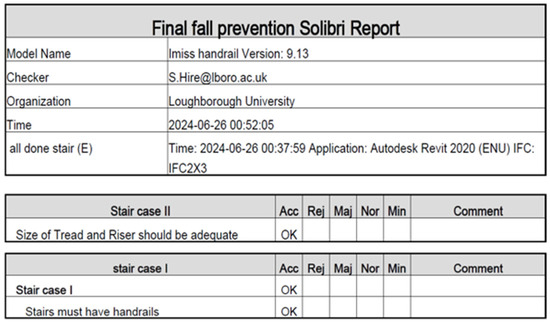
Figure 12.
Rechecking after corrective actions for Scenarios I and II.
3.8. Three-Dimensional Model Creation for Scenario III (Inappropriate Height of Handrails)
Providing handrails is a requirement of OSHA. However, the provided handrail must have adequate dimensions, which is equally important. This case checks whether the height of the provided handrail is appropriate or not. For Scenario III, a sample 3D model of handrails with incorrect height is designed in Autodesk Revit (Figure 13) to check whether the created rule identifies this hazard.
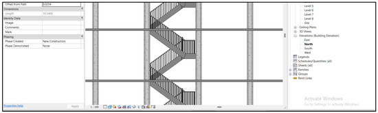
Figure 13.
A 3D model with incorrect height of handrail [Scenario III] created in Revit.
3.9. Rule Interpretation (Scenario III)
After designing Scenario III, the associated safety requirements and rules were reviewed from OSHA standards. As per OSHA, handrails should be installed that are not less than 30 inches (76 cm) and not more than 38 inches (97 cm), as measured from the leading edge of the stair tread to the top surface of the handrail. All the standard dimensions are adopted from the OSHA rule book, and a new rule set is created in Solibri Office. This textual rule is considered while interpreting and converted into parametric format. Figure 14 represents the interpretation for Rule III.

Figure 14.
Safety rule interpretation in Solibri Office for Rule III.
- Rule III: Height of handrail must be appropriate.
3.10. Rule Integration (Scenario III)
For integration, the 3D model is converted into IFC format, as explained in Section 3.3. The converted file is opened in an interpreted platform (Figure 15).
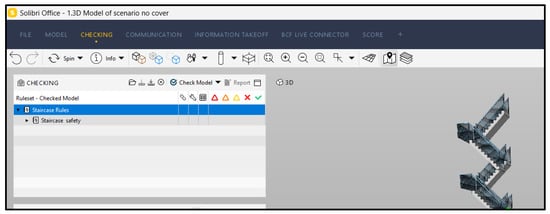
Figure 15.
Integrated model view for Scenario III in Solibri Office.
3.11. Rule Checking (Scenario III)
Once the model is integrated into Solibri, the newly created Rule III is set up by the rule-set manager to check the model. By using the checking tab, the model is run, and results are obtained. The results show identified issues, such as the excess height of the handrail as it is not as per the standard. The rule is successfully run, and the hazard is identified (Figure 16).
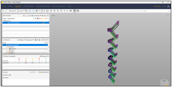
Figure 16.
Rule checking and highlighting the inappropriate dimensions of handrails in purple and the tread border in fluorescent green (Scenario III).
3.12. Reporting for Case III (Scenario III)
A report of identified issues is auto-generated with the details of the location of the possible occurrence of the hazard, enabling the preparation of a corrective action plan (Figure 17).
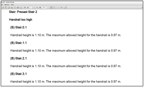
Figure 17.
Generated report of identified hazards (Scenario III).
3.13. Corrective Actions (Scenario III)
In this step, the 3D model is updated by reducing the height of the handrail, as part of corrective actions. All the corrective actions are manually designed in Revit. Figure 18 represents the updated handrail height in Revit.
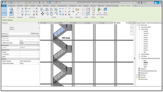
Figure 18.
Corrective actions taken for Case III in 3D model of Revit.
3.14. Recheck and Reporting (Scenario III)
Once again, the model is integrated with the checking platform, and the model is checked for accuracy in the design to avoid accidents. Figure 19 shows the rechecking of the model with corrective actions. It shows that the rule is successfully passed as the height of the handrail is as required by the rule.
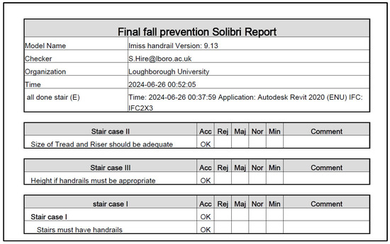
Figure 19.
Rechecking after corrective actions for Case III (Scenarios I, II, III).
For automated checking, the design should be in a form that automated rules can read the objects in the model. The requirements of a rule checker are stricter than the existing 2D drawing or 3D modeling requirements for building models. These models also aid in safety training and enhance communication among stakeholders. Safety officers can virtually review the model and suggest risk-reduction measures early on. The proposed system uses digital safety rules stored in a rule library to automatically check models, detect hazards, and suggest solutions. While reducing human reliance, it still allows expert input when needed. The system ensures that the design complies with codified safety rules from the start, promoting safe construction practices. Moreover, the visibility and detection of each object are very important in the integration process, as the rule checking can only be done if the object is identifiable. Large volumes of safety data are stored systematically throughout the project. These can be reused later, forming a knowledge base for different hazard scenarios.
4. Conclusions
In conventional practices, most safety solutions are reactive rather than proactive, and that causes time overrun. To perform the automatic rule checking by integration and to understand the flow of the process and data exchange from one tool to another, a framework is proposed, which provides the conceptual foundation for facilitating the process of automated safety checking. This research has utilized and demonstrated the applicability of BIM for site safety checking and for providing better safety management. With the staircase being the main source of conveyance in construction, and also a common cause for falls on sites, the three primary causes of staircase falls are considered, which include 1.Missing handrails, 2. Inadequate tread and riser, and 3. Inadequate size of handrail. The rules are interpreted and based on the OSHA regulations, and the rules are identified and interpreted in the system, followed by the identification of hazards. As demonstrated by the conducted research, safety planning can be taken into account at an early stage of construction for the identification of hazard locations and the application of protective measures. This model not only suggests suitable corrective actions as per safety rules, but it also checks the dimensions of the protective system. The BIM-enabled automatic safety checking process provides several direct benefits. The most important one is that it ensures that designs are safer in accordance with safety standards. This automation capability reduces the dependability of manual risk identification and assists humans in making decisions. In addition, the identified risks and preventative measures are more reliable and error-free as they were run through checks that adhere to safety standards. The other significant benefits include a 3D model of the construction project along with visualization of required protective equipment at respective hazard locations. The different safety rules are created from the library of rule sets and can be stored for checking the designs as and when required. The entire process of automatic safety checking requires the involvement of the designer, safety inspector, and project manager, and that enables collaborative work before the commencement of the construction project, leading to better coordination and communication. The application of BIM will enhance the entire project lifecycle in the direction of improved safety design and management, which might boost project delivery efficiency for the construction sector.
The authors recommend that the focus of future studies may be on the performance and applicability of safety rule checking in various types of hazard cases. Additional safety requirements that come from other standards or experience-based solutions may be investigated for codification. Considering the other kinds of complex projects, such as infrastructure, industrial, etc., will aid in exploring applicability and persuade practitioners of its practicality and benefits in safety management.
The presented system identifies and manages the hazards in a virtual environment, which, in conventional practices, usually takes place in the physical environment. Results demonstrated the capabilities of the developed safety checking system. This allows the designer to enhance their design in order to increase safety during the construction project’s entire lifecycle. With the growth of BIM, higher standards for automatic checking systems are emerging. It would be intended for a wide range of applications in the AEC sector throughout both conceptual and legal checking phases. The automatic safety checking presented in this study is thought to accelerate the BIM implementation for site safety at an earlier stage.
Author Contributions
Conceptualization, S.H. and K.R.; Methodology, S.H.; Validation, S.H.; Writing—original draft, S.H.; Writing—review & editing, S.S. and K.R.; Supervision, S.S. and K.R. All authors have read and agreed to the published version of the manuscript.
Funding
This research received no external funding.
Data Availability Statement
Some or all data, models, or code that support the findings of this study are available from the corresponding author upon reasonable request.
Conflicts of Interest
The authors declare no conflicts of interest.
References
- The Economic Times. India’s Construction Sector Second Largest Employment Generator; The Times Group: Mumbai, India, 2023; pp. 24–25. Available online: https://economictimes.indiatimes.com/industry/indl-goods/svs/construction/indias-construction-sector-second-largest-employment-generator-report/printarticle/102399804.cms (accessed on 5 September 2024).
- Jarkas, A.M.; Bitar, C.G. Factors affecting construction labor productivity in Kuwait. J. Constr. Eng. Manag. 2014, 138, 811–820. [Google Scholar] [CrossRef]
- Teizer, J.; Cheng, T. Proximity hazard indicator for workers-on-foot near miss interactions with construction equipment and geo-referenced hazard areas. Autom. Constr. 2015, 60, 58–73. [Google Scholar] [CrossRef]
- OSHA Training Institute. Construction Focus Four: Fall Hazards. 2011. Available online: https://www.osha.gov/sites/default/files/falls_ig.pdf (accessed on 16 September 2024).
- ILO. World Statistic. 2022. Available online: https://www.ilo.org/meetings-and-events/occupational-safety-and-health-management-construction-sector-3 (accessed on 10 December 2023).
- HSE. Construction Statistics in Great Britain. 2020. Available online: https://www.hse.gov.uk/statistics/assets/docs/construction.pdf (accessed on 17 December 2024).
- Sampaio, A.Z.; Sequeira, P.; Gomes, A.M.; Sanchez-Lite, A. BIM Methodology in Structural Design: A Practical Case of Collaboration, Coordination, and Integration. Buildings 2023, 13, 31. [Google Scholar] [CrossRef]
- Paduano, I.; Mileto, A.; Lofrano, E. A Perspective on AI-Based Image Analysis and Utilization Technologies in Building Engineering: Recent Developments and New Directions. Buildings 2023, 13, 1198. [Google Scholar] [CrossRef]
- Umar, T. Key factors influencing the implementation of three-dimensional printing in construction. Proc. Inst. Civ. Eng. Manag. Procure. Law 2020, 174, 104–114. [Google Scholar] [CrossRef]
- Hire, S.; Sandbhor, S.; Ruikar, K. Bibliometric Survey for Adoption of Building Information Modeling (BIM) in Construction Industry—A Safety Perspective. Arch. Comput. Methods Eng. 2021, 29, 679–693. [Google Scholar] [CrossRef]
- Hire, S.; Sandbhor, S.; Ruikar, K.; Amarnath, C.B. BIM usage benefits and challenges for site safety application in Indian construction sector. Asian J. Civ. Eng. 2021, 22, 1249–1267. [Google Scholar] [CrossRef]
- Chantawit, D.; Hadikusumo, B.H.W.; Charoenngam, C.; Rowlinson, S. 4DCAD-Safety: Visualizing project scheduling and safety planning. Constr. Innov. 2005, 5, 99–114. [Google Scholar] [CrossRef]
- ISO 31000:2009; Risk Management—Principles and Guidelines. International Organization for Standardization: Geneva, Switzerland, 2009.
- Bansal, V.K. Application of geographic information systems in construction safety planning. Int. J. Proj. Manag. 2011, 29, 66–77. [Google Scholar] [CrossRef]
- Hire, S.; Sandbhor, S.; Ruikar, K. Technology Landscape for BIM in Construction Site Safety Management. In Proceedings of SECON’23; Springer: Cham, Switzerland, 2023; Volume 381, pp. 931–943. [Google Scholar] [CrossRef]
- Hire, S.; Ranjan, A.; Ruikar, K.; Sandbhor, S. AI-driven safety checks for ladders used on construction sites. IOP Conf. Ser. Earth Environ. Sci. 2022, 1101, 9. [Google Scholar] [CrossRef]
- Gerrish, T.; Ruikar, K.; Cook, M.; Johnson, M.; Phillip, M.; Lowry, C. BIM application to building energy performance visualization and management: Challenges and potential. Energy Build. 2017, 144, 218–228. [Google Scholar] [CrossRef]
- Latiffi, A.A.; Mohd, S.; Kasim, N.; Fathi, M.S. Building Information Modeling (BIM) Application in Malaysian Construction Industry. Int. J. Constr. Eng. Manag. 2013, 2, 1–6. [Google Scholar]
- Sani, M.J.; Rahman, A.A. GIS and BIM Integration At Data Level: A Review. Int. Arch. Photogramm. Remote Sens. Spat. Inf. Sci. 2018, 42, 299–306. [Google Scholar] [CrossRef]
- Alizadehsalehi, S.; Yitmen, I.; Celik, T.; Arditi, D. The effectiveness of an integrated BIM/UAV model in managing safety on construction sites. Int. J. Occup. Saf. Ergon. 2018, 26, 829–844. [Google Scholar] [CrossRef]
- Arslan, M.; Cruz, C.; Ginhac, D. Semantic trajectory insights for worker safety in dynamic environments. Autom. Constr. 2019, 106, 102854. [Google Scholar] [CrossRef]
- Costin, A.M.; Teizer, J.; Schoner, B.; Thingmagic, T. Rfid and Bim-Enabled Worker Location Tracking to Support Real-Time Building Protocol Control and Data Visualization. J. Inf. Technol. Constr. 2015, 20, 495–517. [Google Scholar]
- Cheung, W.F.; Lin, T.H.; Lin, Y.C. A real-time construction safety monitoring system for hazardous gas integrating wireless sensor network and building information modeling technologies. Sensors 2018, 18, 436. [Google Scholar] [CrossRef]
- Vacanas, Y.; Themistocleous, K.; Agapiou, A.; Hadjimitsis, D. Building Information Modelling (BIM) and Unmanned Aerial Vehicle (UAV) technologies in infrastructure construction project management and delay and disruption analysis. In Proceedings of the Third International Conference on Remote Sensing and Geoinformation of the Environment (RSCy2015), Paphos, Cyprus, 16–19 March 2015; Volume 9535. [Google Scholar] [CrossRef]
- Giretti, A.; Carbonari, A.; Naticchia, B.; De Grassi, M. Design and first development of an automated real-time safety management system for construction sites. J. Civ. Eng. Manag. 2009, 15, 325–336. [Google Scholar] [CrossRef]
- Zhang, S.; Teizer, J.; Pradhananga, N.; Eastman, C.M. Workforce location tracking to model, visualize and analyze workspace requirements in building information models for construction safety planning. Autom. Constr. 2015, 60, 74–86. [Google Scholar] [CrossRef]
- Zhou, Z.; Irizarry, J.; Li, Q. Applying advanced technology to improve safety management in the construction industry: A literature review. Constr. Manag. Econ. 2013, 31, 606–622. [Google Scholar] [CrossRef]
- Kim, I.; Lee, Y.; Choi, J. BIM-based hazard recognition and evaluation methodology for automating construction site risk assessment. Appl. Sci. 2020, 10, 7. [Google Scholar] [CrossRef]
- Umar, T. Challenges of BIM implementation in GCC construction industry. Eng. Constr. Archit. Manag. 2022, 29, 1139–1168. [Google Scholar] [CrossRef]
- Zhang, S.; Teizer, J.; Lee, J.K.; Eastman, C.M.; Venugopal, M. Building Information Modeling (BIM) and Safety: Automatic Safety Checking of Construction Models and Schedules. Autom. Constr. 2013, 29, 183–195. [Google Scholar] [CrossRef]
- Mihić, M. Incorporation of Health and Safety into Building Information Modelling Through Hazard Integration System. Ph.D. Thesis, University of Zagreb, Zagreb, Croatia, 2018. [Google Scholar] [CrossRef]
- Khemlani, L. CORENET e-PlanCheck: Singapore’s Automated Code Checking System. 2005. Available online: https://www.aecbytes.com/feature/2005/CORENETePlanCheck.html (accessed on 25 February 2023).
- Pauwels, P.; Terkaj, W.; Sarr, S.; Gatti, S.; Van den Brink, L.; Oosterom, P.; De Backer, H.; Vandenbroucke, E.; Beetz, J.; Valente, M.; et al. A semantic rule checking environment for building performance checking. Autom. Constr. 2011, 20, 506–518. [Google Scholar] [CrossRef]
- Park, S.; Lee, Y.C.; Lee, J.K. Definition of a domain-specific language for Korean building act sentences as an explicit computable form. J. Inf. Technol. Constr. 2016, 21, 422–433. [Google Scholar]
- Zhang, J.; El-Gohary, N.M. Semantic NLP-Based Information Extraction from Construction Regulatory Documents for Automated Compliance Checking. J. Comput. Civ. Eng. 2016, 30, 04015014. [Google Scholar] [CrossRef]
- Hire, S.; Sandbhor, S.; Ruikar, K. A Conceptual Framework for BIM-Based Site Safety Practice. Buildings 2024, 14, 272. [Google Scholar] [CrossRef]
- Weekly Safety. Safety Considerations for Graphene.pdf. Available online: https://weeklysafety.com/blog/construction-stairways#:~:text=Keep%20loose%20tools%20and%20trash,have%20safety%20barricades%20in%20place (accessed on 3 April 2024).
- OSHA 1910.25; Stairways. Occupational Safety and Health Administration, U.S Department of Labor: Washington, DC, USA, 2018. Available online: https://www.osha.gov/laws-regs/regulations/standardnumber/1910/1910.25 (accessed on 3 April 2024).
Disclaimer/Publisher’s Note: The statements, opinions and data contained in all publications are solely those of the individual author(s) and contributor(s) and not of MDPI and/or the editor(s). MDPI and/or the editor(s) disclaim responsibility for any injury to people or property resulting from any ideas, methods, instructions or products referred to in the content. |
© 2025 by the authors. Licensee MDPI, Basel, Switzerland. This article is an open access article distributed under the terms and conditions of the Creative Commons Attribution (CC BY) license (https://creativecommons.org/licenses/by/4.0/).