

A Study of Residual Shear Strength in Severely Corroded Steel Girder Ends


Abstract
1. Introduction
2. Corrosion Damage and Model Setup
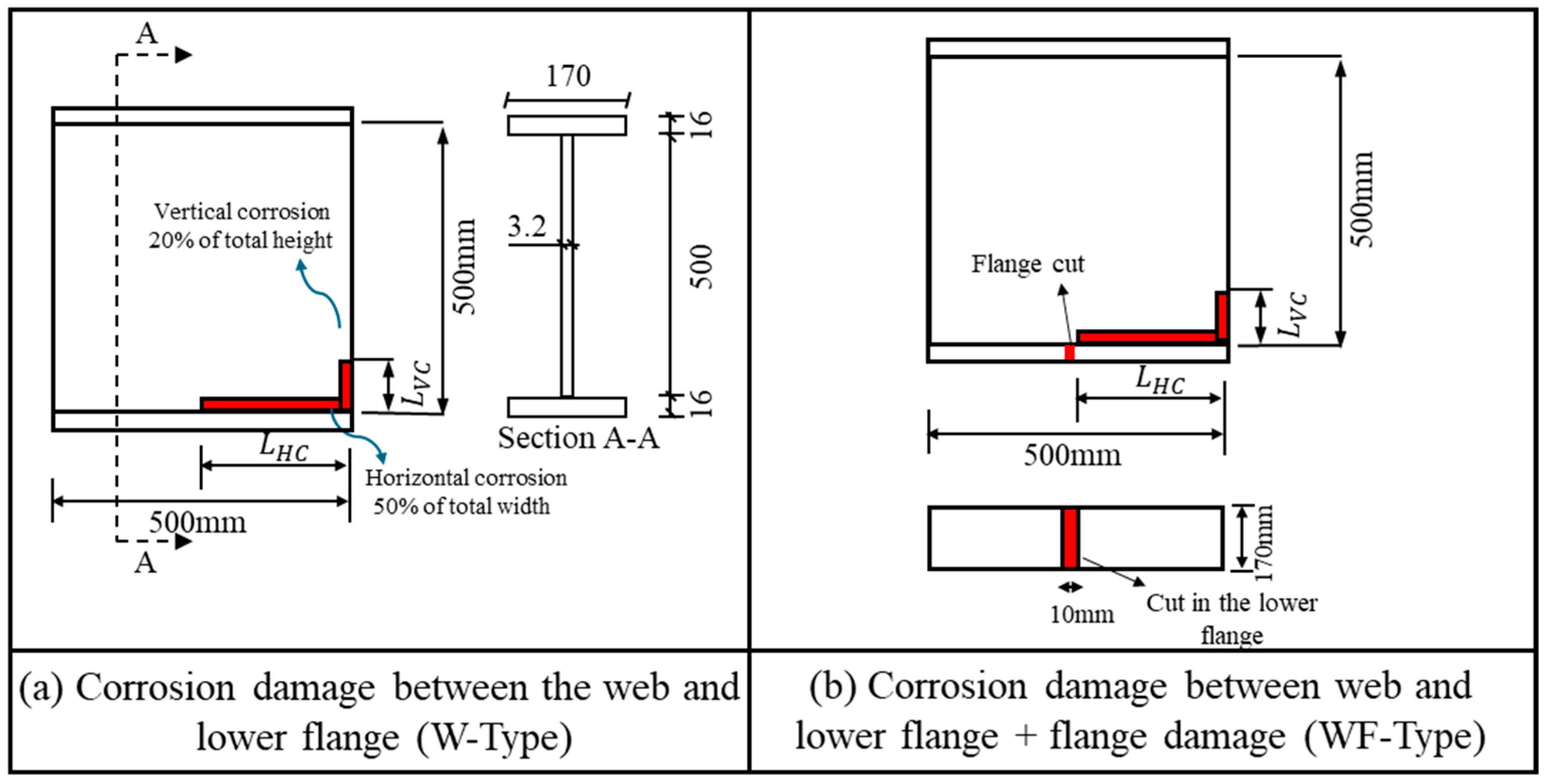
2.1. Categorizing Corrosion Patterns
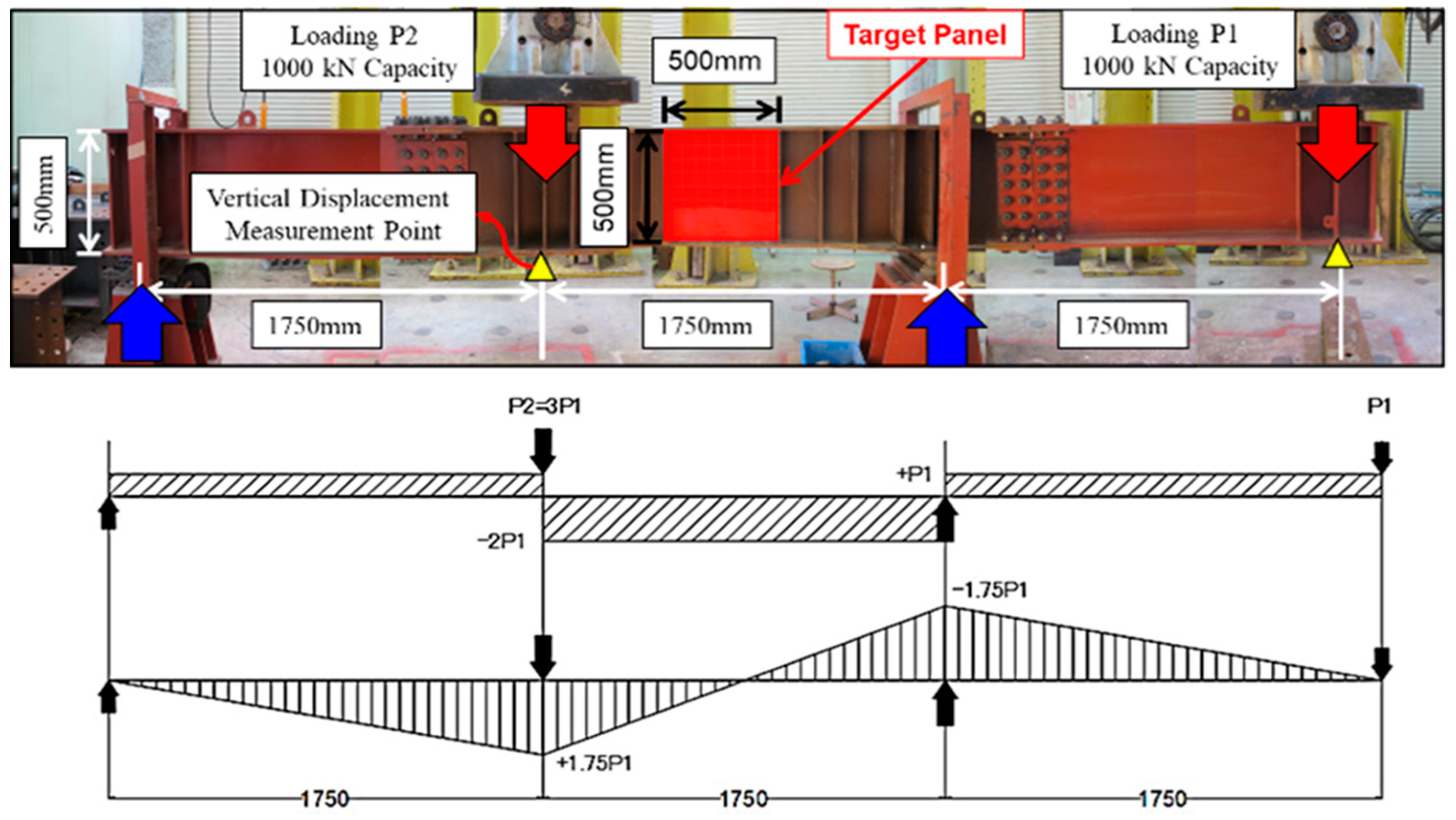
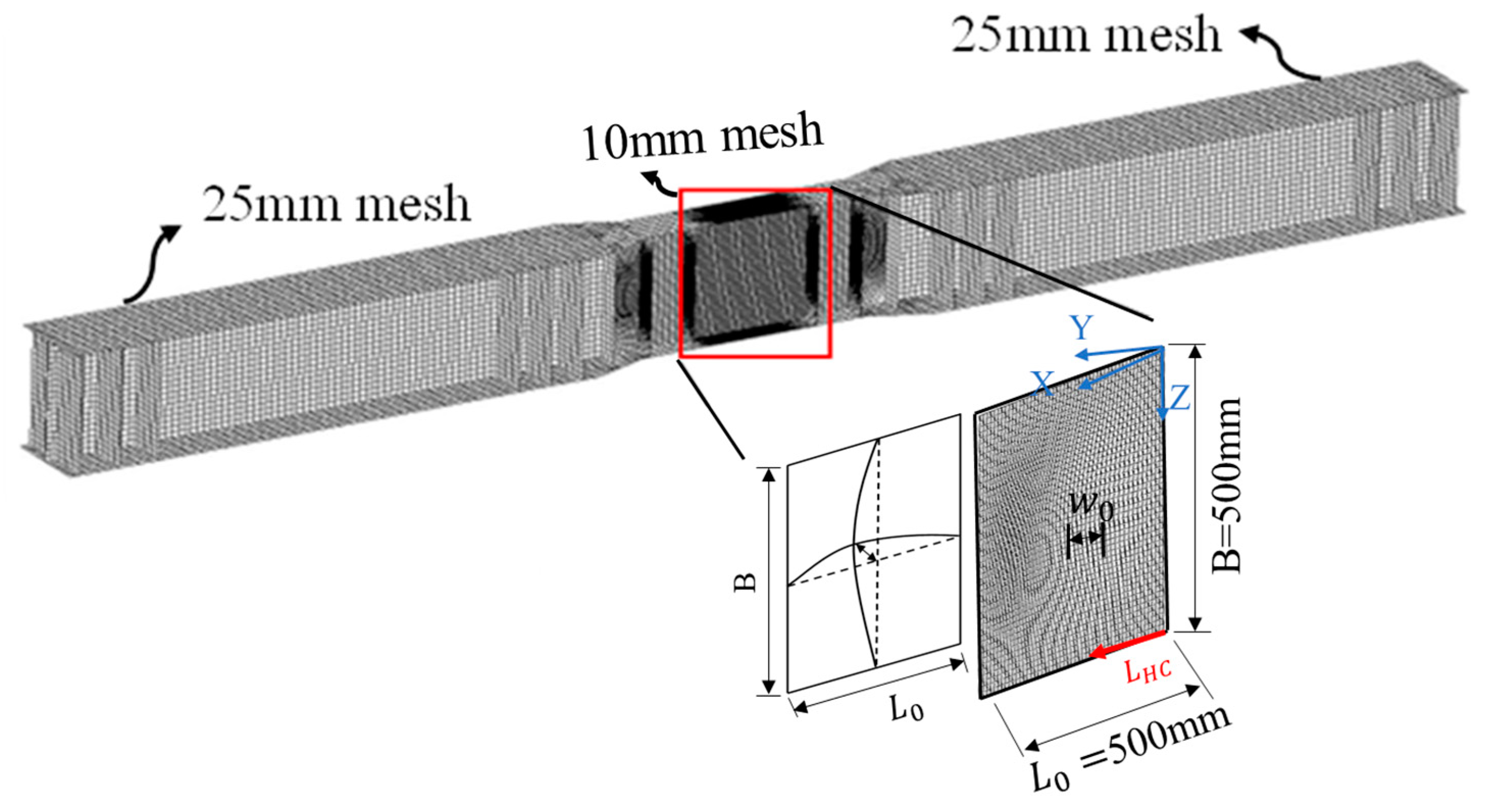
2.2. Experimental Model for Evaluation of Shear Strength
2.3. Considering Corroded Patterns
3. Evaluating Residual Strength of Damaged Cases
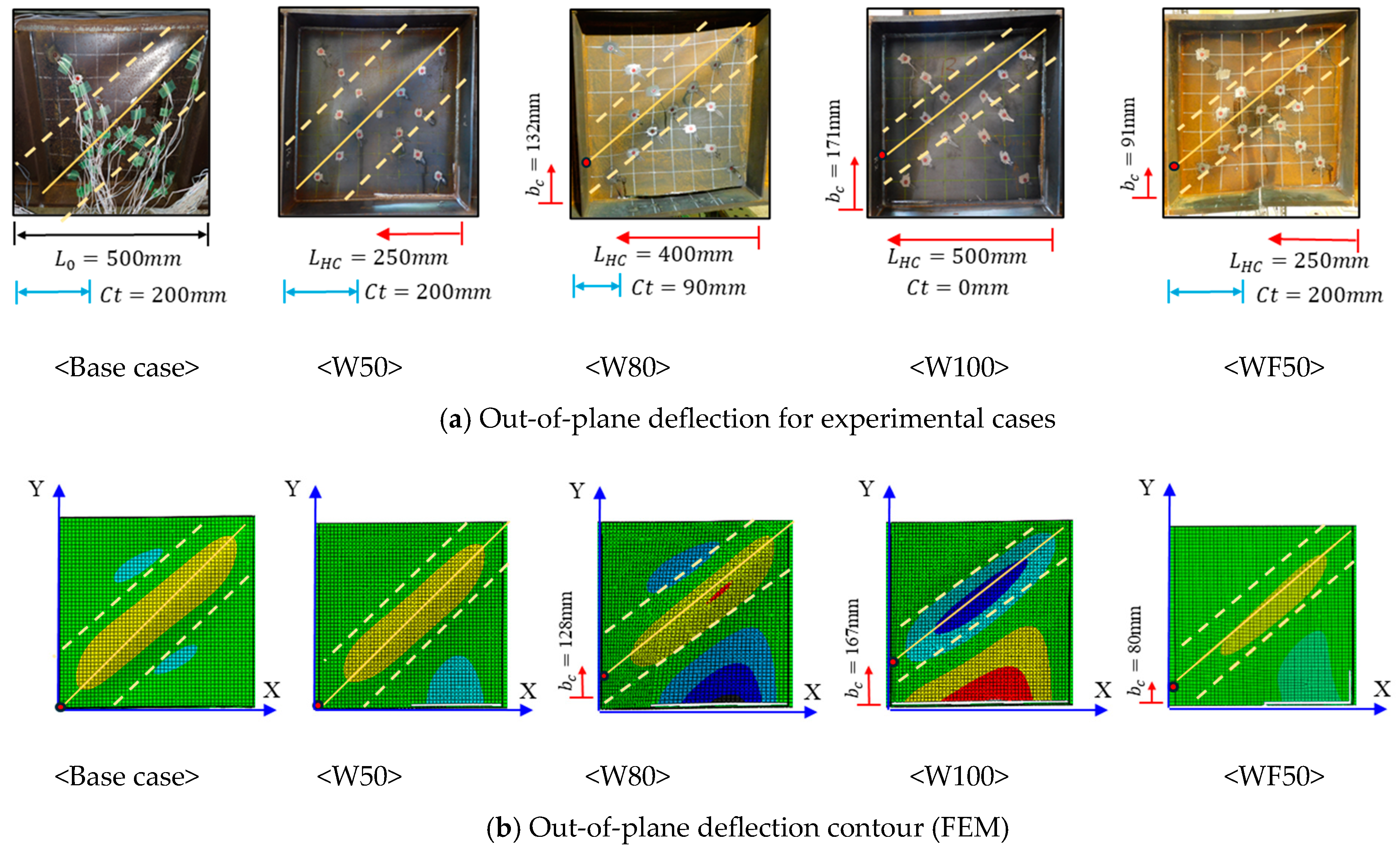
3.1. Effect of Severe Corrosion over Tension Field Action
3.2. Experimental Results and Numerical Method Validation
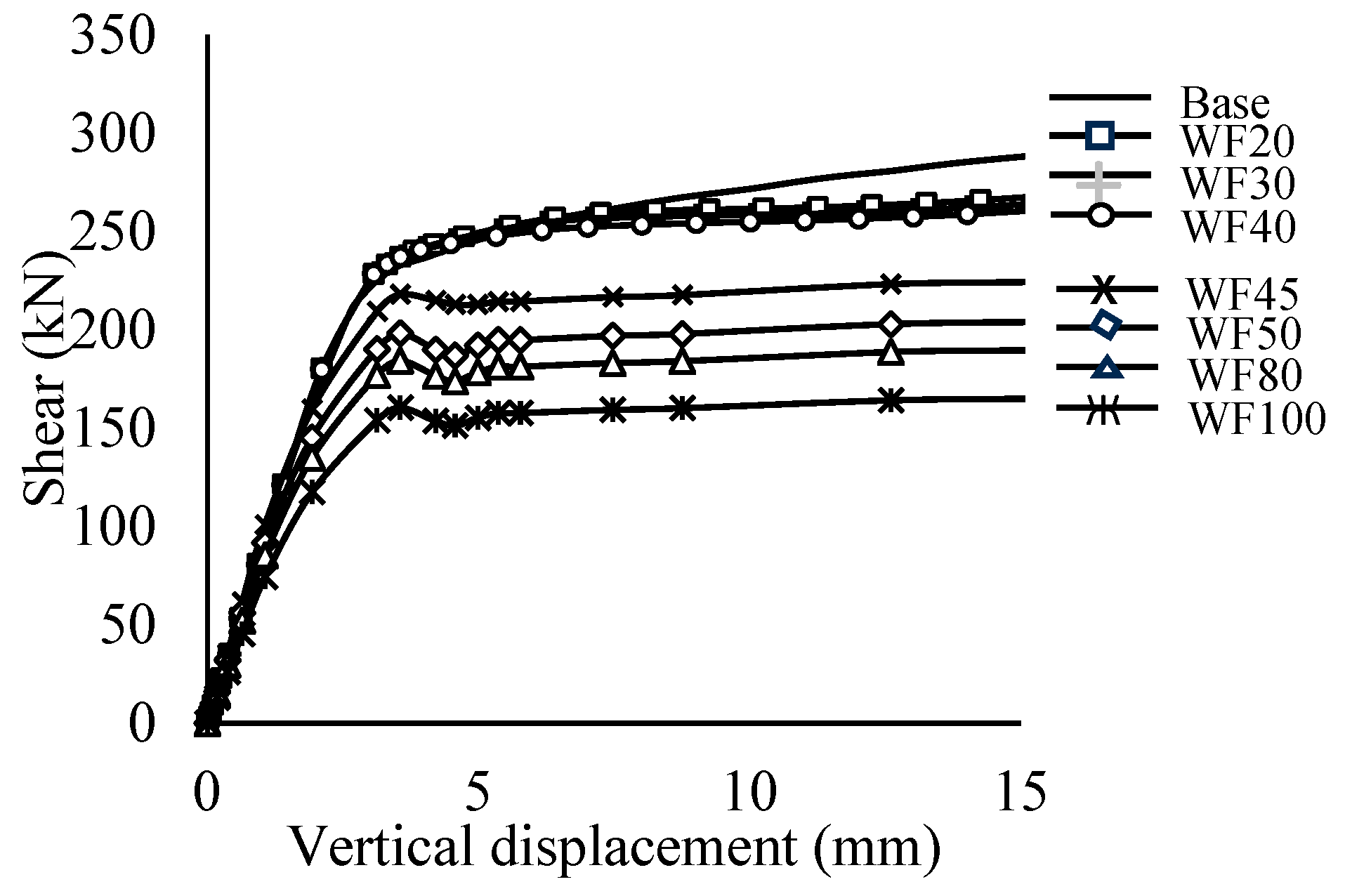
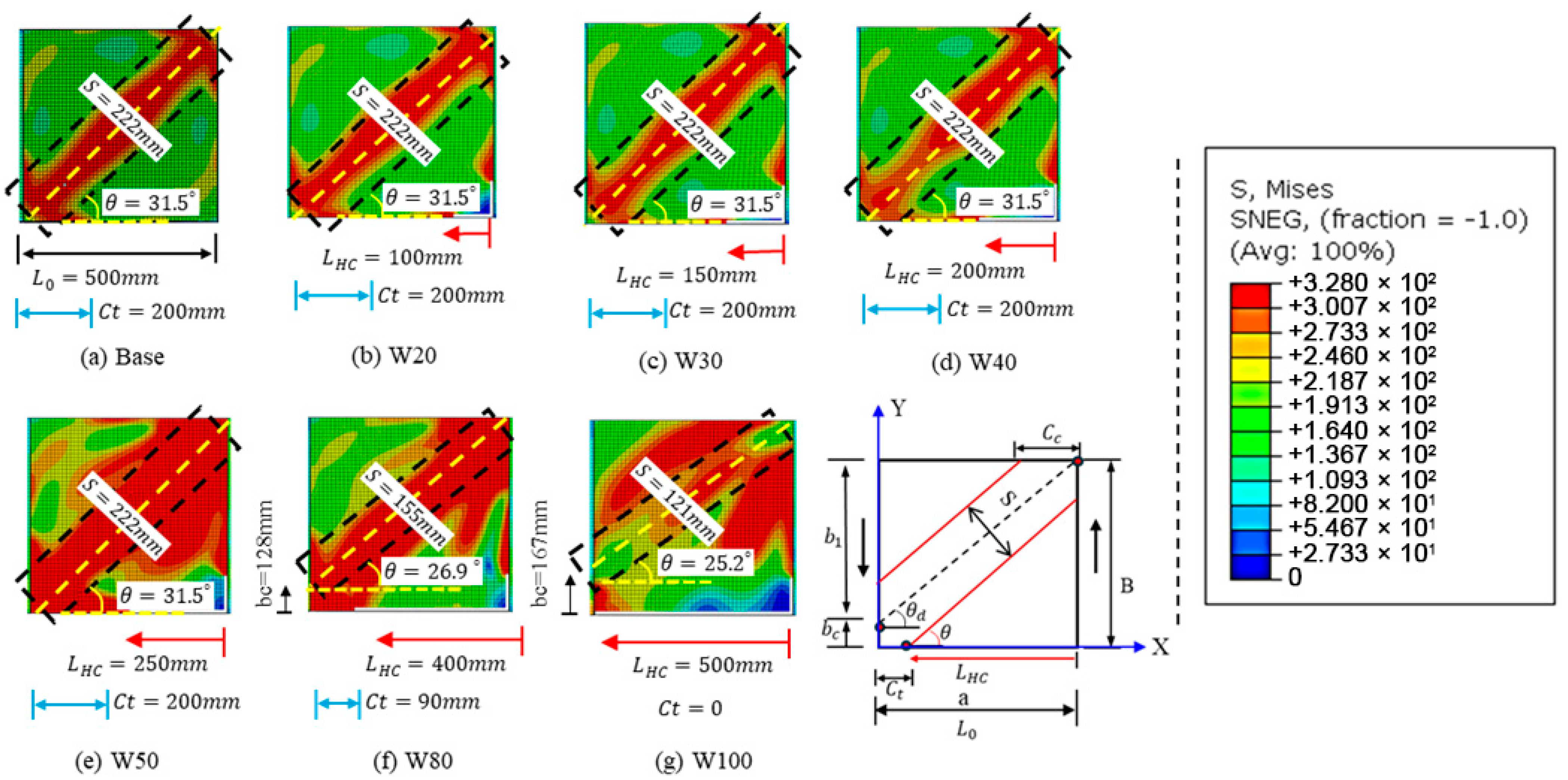
3.3. Numerical Parametric Results
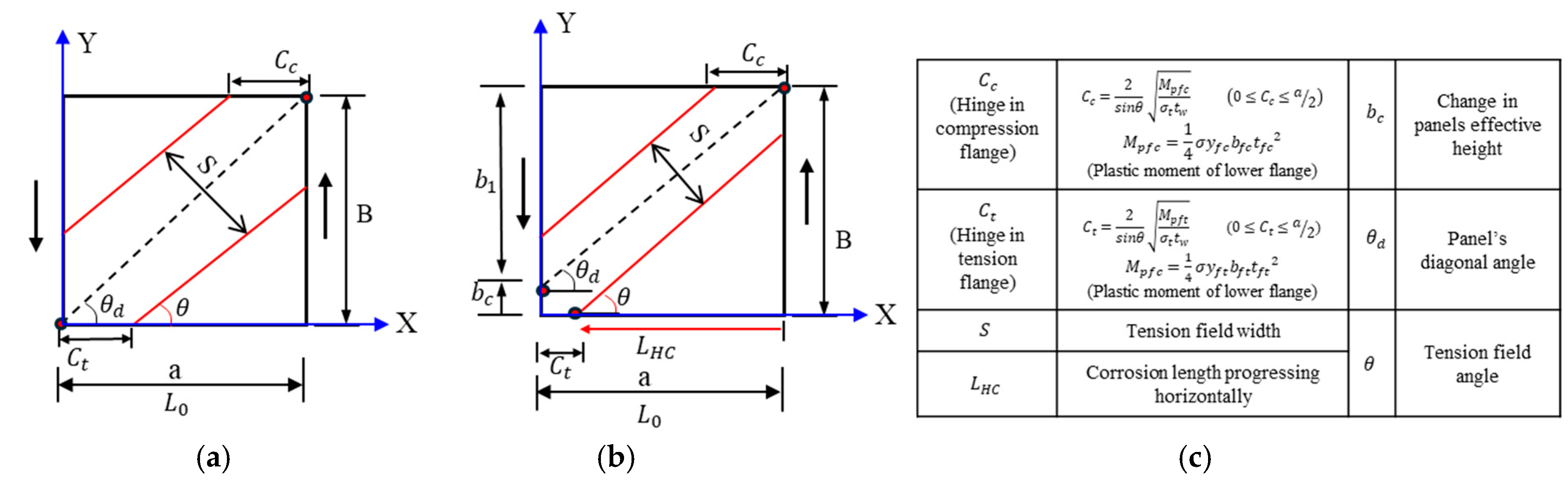
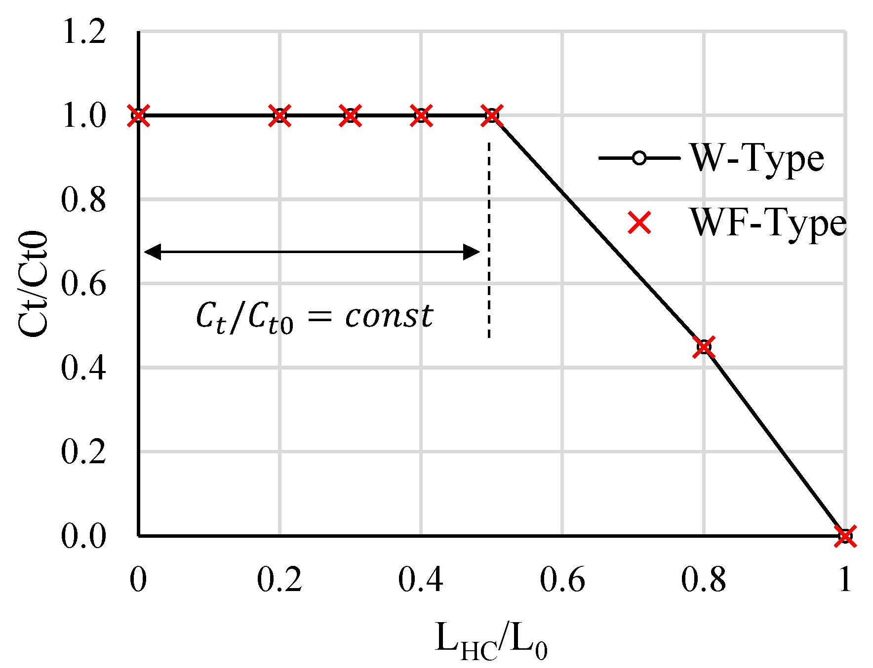
3.4. Mechanism of the Decline in Post-Buckling Strength
- a.
- W-Type
- b.
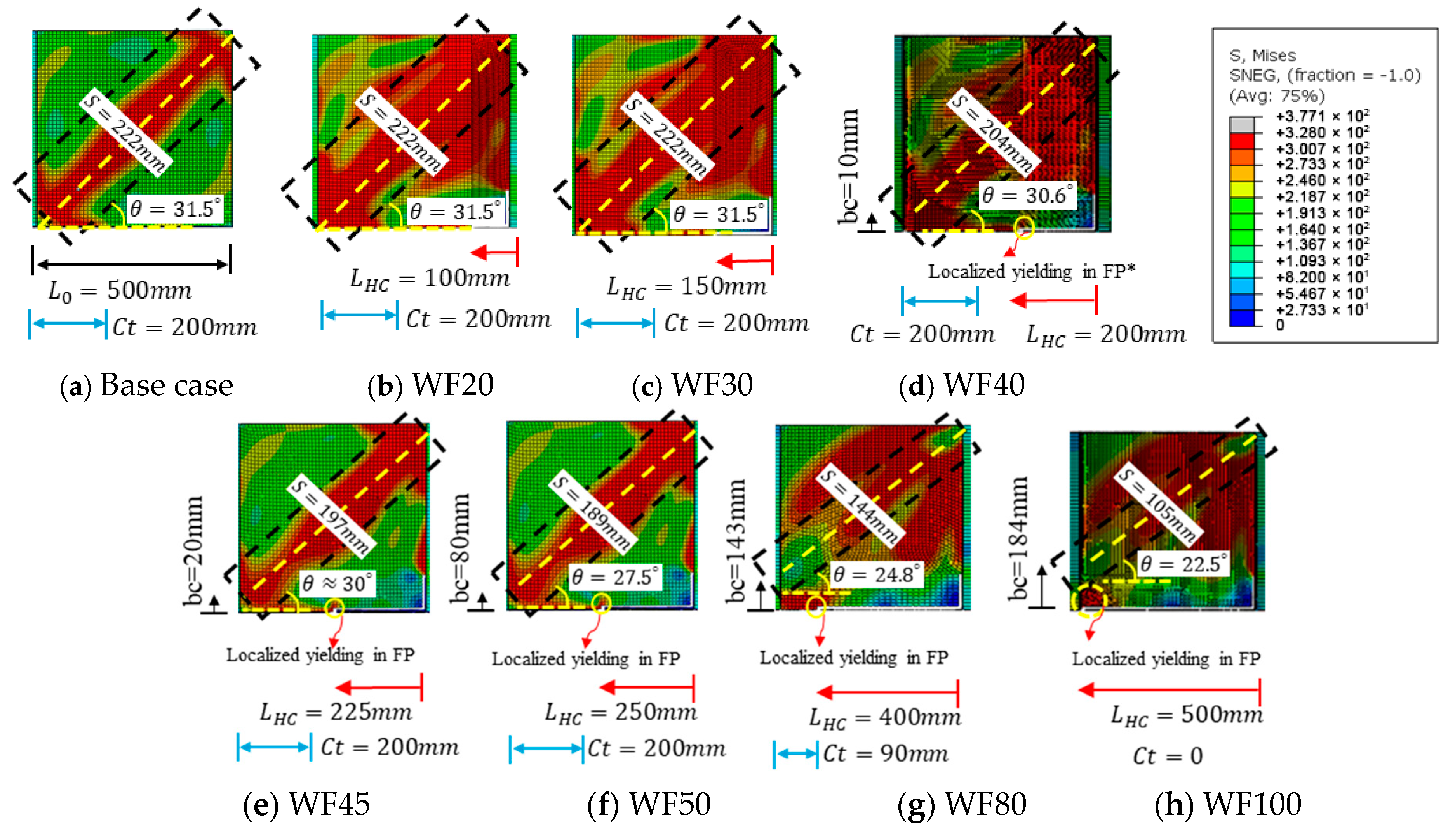
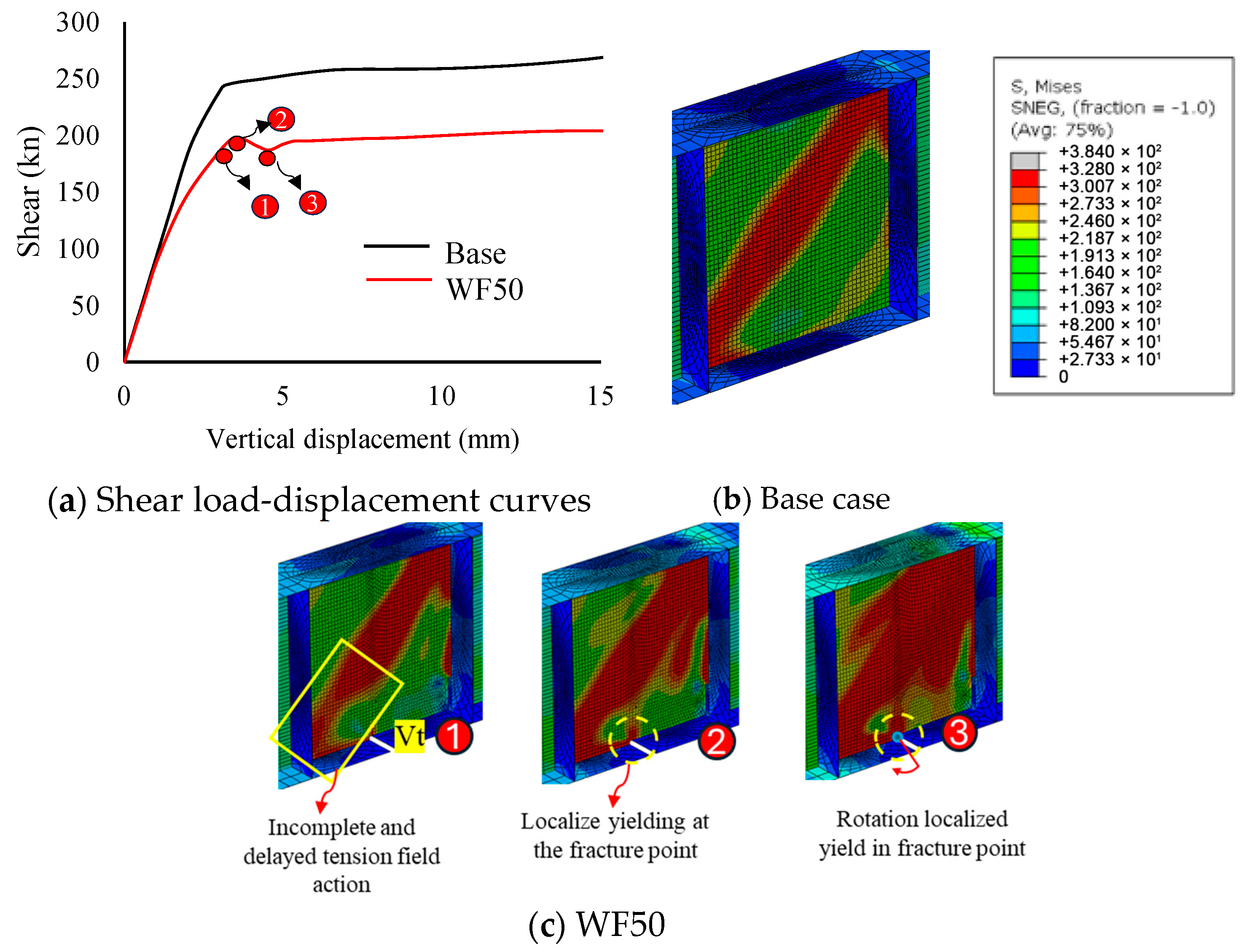
- WF-Type
4. Conclusions
- In W-Type corrosion patterns, where the damage disconnects the web from the lower flange and predominantly affects the web, a gradual decline in post-buckling strength is observed beyond LHC/L0≥50%. This decline is attributed to the narrowing of the tension field width, which induces a shift in the plastic hinge (Ct) on the lower flange affecting the location of the anchorage. Consequently, this shift results in the rotation of the inclination angle, reducing the effective area of the tension field and leading to a reduction in post-buckling shear strength.
- In WF-Type corrosion patterns, where the web and lower flange are disconnected along with a transverse cut in the lower flange, post-buckling strength begins to decline at approximately LHC/L0≥40%. Corrosion damage to the lower flange, combined with web deterioration, leads to the formation of a localized yield point near the flange cut referred to as a fracture point. This fracture point results in a hinge-like rotation and causes the tension field’s inclination angle to abruptly rotate, reducing its effective area and resulting in a sudden decrease in post-buckling strength.
Author Contributions
Funding
Data Availability Statement
Conflicts of Interest
References
- Yamaguchi, E.; Akagi, T.; Tsuji, H. Influence of corrosion on load-carrying capacities of steel I-section main-girder end and steel end cross-girder. Int. J. Steel Struct. 2014, 14, 831–841. [Google Scholar] [CrossRef]
- Liu, C.; Miyashita, T.; Nagai, M. Analytical study on shear capacity of steel I-girders with local corrosion nearby supports. Procedia Eng. 2011, 14, 2276–2284. [Google Scholar] [CrossRef]
- Chiu, C.K.; Liao, I.H.; Yamaguchi, E.; Lee, Y.C. Study on the simplified evaluation method of the remaining load-carrying capacity of a corroded steel I-girder end using FEA. J. Constr. Steel Res. 2023, 210, 108045. [Google Scholar] [CrossRef]
- Khurram, N.; Sasaki, E.; Katsuchi, H.; Yamada, H. Finite element investigation of shear capacity of locally corroded end panel of steel plate girder. Int. J. Steel Struct. 2013, 13, 623–633. [Google Scholar] [CrossRef]
- Sharifi, Y. Residual Web Bearing Capacity of Corroded Steel Beams. Adv. Steel Constr. 2012, 8, 242–255. [Google Scholar]
- Rahgozar, R. Remaining capacity assessment of corrosion damaged beams using minimum curves. J. Constr. Steel Res. 2009, 65, 299–307. [Google Scholar] [CrossRef]
- Bao, A.; Guillaume, C.; Satter, C.; Moraes, A.; Williams, P.; Kelly, T.; Guo, Y. Testing and evaluation of web bearing capacity of corroded steel bridge girders. Eng. Struct. 2021, 238, 112276. [Google Scholar] [CrossRef]
- Japan Society of Civil Engineers. Guidelines for Stability Design of Steel Structures, 1st ed. 2007. Available online: https://www.jsce-int.org/about/guideline (accessed on 12 January 2025).
- Mumtaz, Y.; Shimozato, T.; Yamashita, S. A study on effective rehabilitation method of shear buckling strength by CFRP in steel girder. Structures 2023, 56, 105008. [Google Scholar] [CrossRef]
- Basler, K. Strength of plate girders in shear. J. Struct. Div. 1961, 87, 151–180. [Google Scholar] [CrossRef]


| Cases | Case Name | (%) | (%) |
|---|---|---|---|
| 1 | Base | - | - |
| 2 | W50 | 50 | - |
| 3 | W80 | 80 | - |
| 4 | W100 | 100 | - |
| 5 | WF50 | 50 | 50 |
| Cases | Base | W20 | W30 | W40 | W50 | W80 | W100 | WF20 | WF30 | WF40 | WF45 | WF50 | WF80 | WF100 |
|---|---|---|---|---|---|---|---|---|---|---|---|---|---|---|
| Damage Patterns | ||||||||||||||
| Web damage LHC/L0 (%) | - | 20 | 30 | 40 | 50 | 80 | 100 | 20 | 30 | 40 | 45 | 50 | 80 | 100 |
| Flange damage LHC/L0 (%) | - | - | - | - | - | - | - | 20 | 30 | 40 | 45 | 50 | 80 | 100 |
Disclaimer/Publisher’s Note: The statements, opinions and data contained in all publications are solely those of the individual author(s) and contributor(s) and not of MDPI and/or the editor(s). MDPI and/or the editor(s) disclaim responsibility for any injury to people or property resulting from any ideas, methods, instructions or products referred to in the content. |
© 2025 by the authors. Licensee MDPI, Basel, Switzerland. This article is an open access article distributed under the terms and conditions of the Creative Commons Attribution (CC BY) license (https://creativecommons.org/licenses/by/4.0/).
Share and Cite
Mumtaz, Y.; Shimozato, T.; Kenta, N.; Naoki, M. A Study of Residual Shear Strength in Severely Corroded Steel Girder Ends. CivilEng 2025, 6, 14. https://doi.org/10.3390/civileng6010014
Mumtaz Y, Shimozato T, Kenta N, Naoki M. A Study of Residual Shear Strength in Severely Corroded Steel Girder Ends. CivilEng. 2025; 6(1):14. https://doi.org/10.3390/civileng6010014
Chicago/Turabian StyleMumtaz, Yasin, Tetsuhiro Shimozato, Nitta Kenta, and Matsui Naoki. 2025. "A Study of Residual Shear Strength in Severely Corroded Steel Girder Ends" CivilEng 6, no. 1: 14. https://doi.org/10.3390/civileng6010014
APA StyleMumtaz, Y., Shimozato, T., Kenta, N., & Naoki, M. (2025). A Study of Residual Shear Strength in Severely Corroded Steel Girder Ends. CivilEng, 6(1), 14. https://doi.org/10.3390/civileng6010014