Article

Ensuring Structural Integrity: An Evaluation of Vertical Shortening in Tall Concrete Buildings

1
Department of Building Construction and Transport Infrastructure, Faculty of Civil Engineering, Polytechnic University of Tirana, 1001 Tirana, Albania
2
Department of Mechanics of Structures, Faculty of Civil Engineering, Polytechnic University of Tirana, 1001 Tirana, Albania
3
Institute of Forestry and Engineering, Estonian University of Life Sciences, 51006 Tartu, Estonia
4
Association of Talent under Liberty in Technology (TULTECH), Sopruse Pst, 10615 Tallinn, Estonia
5
Faculty of Mechatronics, Informatics and Interdisciplinary Studies, Technical University of Liberec, 461 17 Liberec, Czech Republic
6
Institute for Nanomaterials, Advanced Technologies and Innovation, Technical University of Liberec, 461 17 Liberec, Czech Republic
*
Author to whom correspondence should be addressed.
CivilEng 2024, 5(1), 191-208; https://doi.org/10.3390/civileng5010010
Submission received: 31 December 2023 / Revised: 29 January 2024 / Accepted: 4 February 2024 / Published: 7 February 2024
(This article belongs to the Section Construction and Material Engineering)

Abstract

:
Vertical shortening, a phenomenon inherent to concrete structures, plays a key role in the quality and safety of construction, particularly in tall reinforced concrete buildings. This behavior is intrinsically linked to the time-dependent properties of concrete, encompassing both creep and shrinkage. Neglecting these aspects, especially when non-uniformly distributed, can give rise to various structural issues, including partition distress, overloading, and potential cracking in horizontal elements. This paper delves into the principal factors influencing vertical shortening and presents a rigorous approach to their evaluation, treating creep and shrinkage as critical parameters. The investigation employs two illustrative case studies: the first revolves around a 15-story reinforced concrete building with single columns supporting tributary areas at various levels, acting as a calibration case; the second encompasses a 30-story reinforced concrete structure employing a dual system, providing a broader perspective applicable to three-dimensional structures. A diverse array of analyses is conducted, incorporating considerations for concrete’s linear and nonlinear behavior as well as the impact of construction stages. Our findings reveal that vertical shortening is directly proportional to the building’s height and inversely related to concrete strength, longitudinal reinforcement ratios, member dimensions, volume-to-surface ratios, age of the structure upon load application, and relative humidity. Consequently, precise assessments of differential shortening effects are paramount. The utilization of staged construction analysis and time-dependent effects is recommended as the most suitable approach for evaluating vertical shortening effects.

1. Introduction

Concrete structures are vital components of the modern built environment and urbanism, providing essential support for various applications, ranging from residential buildings to large-scale infrastructure [1,2]. Ensuring the structural integrity and safety of these constructions is paramount, and one critical aspect influencing their performance is the phenomenon of vertical shortening [3]. As urbanization continues to drive the demand for taller structures, understanding and accurately predicting vertical shortening becomes increasingly essential. This phenomenon, mainly caused by time-dependent concrete properties such as creep and shrinkage, has a profound impact on the quality and longevity of reinforced concrete high-rise buildings.
Creep and shrinkage are intrinsic properties of concrete that result from the continuous changes in volume experienced by concrete over time. Creep is characterized by the gradual deformation and settlement of concrete under sustained loading, while shrinkage refers to the decrease in concrete volume due to moisture loss, evaporation, and cement hydration reactions. These two properties contribute to the overall shortening of concrete members, and their effects can be particularly pronounced in tall buildings due to the larger height and mass of concrete elements. The consequences of unmitigated vertical shortening can be far-reaching, manifesting as distress in partition walls, structural overstress, and, in severe cases, horizontal cracking in building components. Understanding the factors influencing vertical shortening and accurately evaluating their impact is crucial for optimizing the design and construction of high-rise concrete structures. Factors such as the concrete strength, longitudinal reinforcement ratio, member size, volume-to-surface ratio, and the age of the structure when loading occurs are significant contributors to vertical shortening. Furthermore, relative humidity levels play a critical role in determining the extent of shrinkage. As the height of the structure increases, vertical shortening becomes more pronounced, making it vital to understand these parameters’ intricate interplay to mitigate potential issues [4,5,6,7].
In previous research, various studies have delved into the prediction and assessment of vertical shortening in concrete structures [8,9,10,11]. These studies have employed a wide array of analytical techniques and experimental methodologies, and the findings have provided valuable insights into the behavior of tall buildings subjected to vertical shortening. Some have utilized advanced numerical modeling approaches, considering both linear and nonlinear concrete behavior as well as the effects of different construction stages. Others have investigated practical case studies to evaluate real-world applications of vertical shortening mitigation strategies.
The first studies related to vertical shortening due to time-dependent effects were conducted during the 1950s, while at the time this was considered quite an academic subject. Although researchers were familiar with some aspects of these influencing factors, structural engineers rarely considered them quantitatively in their designs (it was a normal procedure for long-span bridges) [12]. The end of this technical approach came naturally with the need to build higher. During this development process, time proved what somehow was foreseen by researchers: a number of multistorey reinforced concrete buildings where these effects were neglected developed partition distress, as well as structural overstress, and in some cases, cracking in horizontal elements, while in tall buildings with vertical structural elements made of steel, cracking did not present a problem since differential shortening was only related to the elastic behavior of columns and the construction methods used, and somehow the mixed concrete + steel buildings where long-term effects were limited to the differential shortening between the steel columns and the concrete staircase core were immune. In the 1970s, the first specific publications arrived, among them those of the pioneers Mark Fintel and Fazlur Rahman Khan [13,14,15,16], followed by many others. Nowadays, creep and shrinkage effects are widely discussed and are an important part of reinforced concrete structural design codes [17,18,19,20,21]. The development of high-strength concrete and new structural systems allowed for tall buildings to be built entirely of concrete structural elements, so that the problems related to vertical shortening and, furthermore, differential shortening have become more and more important to the present day [22].
However, despite these endeavors, gaps in the current state of the art persist. The existing body of knowledge lacks a comprehensive synthesis of the critical factors influencing vertical shortening, along with a rigorous methodology for their evaluation. Additionally, there is a need for further research that extends the investigation to encompass more complex three-dimensional structures, as the majority of prior studies have focused on specific case studies with limited application to broader building typologies.
The primary objectives of this study are to identify and analyze the principal factors influencing vertical shortening in high-rise concrete structures and to develop a robust methodology for their accurate evaluation. This investigation will take into account the concrete’s time-dependent properties, construction stages, and various design parameters, providing a holistic perspective on vertical shortening. This study’s outcomes will contribute to a deeper understanding of the phenomenon, ultimately enhancing the safety and longevity of tall reinforced concrete buildings. By addressing the current research gap, this study aims to offer valuable insights that can inform engineering practice, support the design of resilient structures, and contribute to the sustainable development of urban environments.

2. Time-Dependent Effects of Concrete in High-Rise Buildings

The Introduction section briefly presented what could be noticed in high-rise reinforced concrete buildings where the time-dependent effects of concrete were neglected. To understand why, it is important to better understand these effects and their influence mechanisms in the vertical elements. With the increasing height of buildings, the importance of time-dependent shortening becomes more critical due to the cumulative nature of such phenomena. Currently, it is common practice to ignore the effects of inelastic and elastic column and wall shortening on the frame; for low- and intermediate-rise buildings, this may be acceptable; however, in high-rise buildings, neglecting the differential shortening may result in cracking and other non-structural and structural deformations to elements of the building, as shown in Figure 1 [23]. Possibly, more forces (bending moments) can be induced into the horizontal structural elements, particularly in the higher reaches of the structure, and unwanted floor slopes may be observed. As a consequence, the stress distribution in the vertical elements can be different from the design values; compensations are needed to assure a proper final position for each floor slab within the building [22]. The influence mechanism is briefly discussed in this section by commenting mainly in qualitative terms on its basic factors; more details for creep and shrinkage are given further.

2.1. Effect of Construction Time

The quantity of creep for a particular concrete mix is mostly dependent on the loading history in addition to the overall stress [12]. It is commonly known that a concrete specimen with an early application of load displays a significantly bigger specific creep than one loaded later in its lifetime. Also, owing to the gradual increase in the modulus of elasticity with age, the elastic shortening per unit stress of older concrete is smaller than that of concrete loaded at an earlier age. Loading history is particularly significant for columns of multistorey buildings that are loaded in increments equal to the number of stories above the level under investigation.

2.2. Effect of Structural Elements Casting Time

A significant difference in shortening may happen because of a time lapse in the casting process of structural parts, like between a slip-formed core and the columns. In this particular scenario, the columns undergo complete creep and shrinkage, although the core may have undergone the majority of its inelastic shortening prior to the neighboring columns being cast.

2.3. Effects of Member Size and Reinforcement

Variable creep and shrinkage strains are anticipated in columns and walls with variable volume-to-surface ratios and percentages of reinforcement [12]. Both creep and shrinkage depend on the member size, but not to the same degree. Shrinkage is more sensitive to member size than creep. Meanwhile, longitudinal reinforcement is the most predominant effect, restraining or positive, on creep and shrinkage. While the extent of creep and shrinkage in specimens of plain concrete might vary significantly depending on the concrete properties and climatic conditions, due to this effect, the ultimate inelastic strain variation in reinforced concrete vertical structural elements is minor. Based on this concept, strains are diminished when the volume-to-surface ratio and reinforcing percentage rise under equivalent loading circumstances and stresses. Objective factors may cause adjacent columns in a multistory building to have differing reinforcing percentages. Differential elastic or inelastic shortening creates moments in connected beams or slabs and transfers load to the shorter portion. As stories rise, cumulative differential shortening and related effects worsen. Often, a huge, extensively reinforced column attracts loads from the nearby shear wall, which has higher creep and shrinkage due to a lower reinforcing percentage and volume-to-surface ratio (has lesser influence). Based on the literature review, it can be noticed with surprise that most of the models of concrete time-dependent properties, included even in the design codes, do not correlate their expressions directly and explicitly with the longitudinal reinforcement ratio (exceptions), for example, in the Portland Cement Association (PCA) guidelines [14].
In conclusion, in order to correctly evaluate the vertical shortening effects, including the elastic ones, based on the influence mechanism presented, among others, in principle, the following procedure is recommended [12]:
(a)
Calculating the amount of creep and shrinkage that occurs in columns and walls while taking the member size, environment, percentage of reinforcement, and history of loading into account.
(b)
Establishing the amount of elastic shortening in columns and walls as necessary for analysis.
(c)
Analysis and structural design for the impacts of vertical load-bearing members’ differential inelastic and elastic shortening.

3. Creep and Shrinkage Models

The analysis results depend not only on the chosen method(s) but also on how the method is applied. In simple terms, in order to have reliable results for the concrete time-dependent effects, the analysis must be based on an exact model of their relatedness, i.e., for creep and shrinkage. Over time, several different models have evolved, and the most known and used are briefly presented below:
(a)
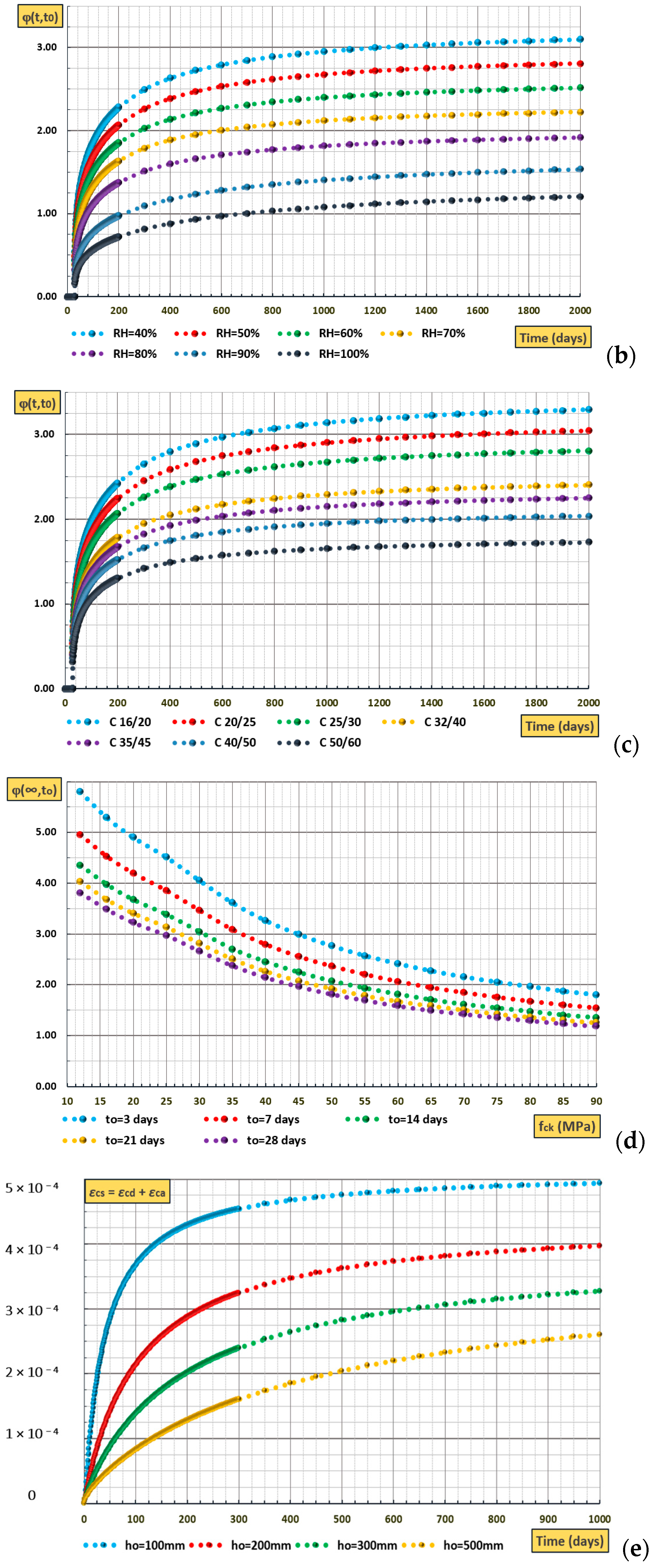
The CEB-FIP Model 1990 (Comité Euro-International du Beton, Fédération Internationale de la Précontrainte) suggests using the CEB 90 Model Code [24]. The following factors are considered for the prediction of creep and shrinkage: relative humidity, exposure of concrete members to the temperature prior to drying, concrete member size, cement type, cement modulus, and concrete age at loading. Neither the effects of curing duration nor the method is accounted for in this model. Applying it to concretes with relative humidity levels between 40 and 100% and a mean temperature of 5–30 °C. It is valid for normal-weight concrete with an average 28-day compressive strength of 20–90 MPa. This model serves as a basis for EC 2.
(b)
The CEB-FIP Model 2010 suggests using the CEB 2010 Model Code [25], which, as it can be understood, is an upgrade of the previous codes and models as a result of new material use and concrete technology advancements. A broader variety of concrete grades is covered by the model. For ease of use and adoption at the design level, a number of influencing parameters are removed from the model, greatly reducing the complexity of creep prediction. Final creep coefficients for up to 50 years of loading are predicted by the model.
(c)
The American Concrete Institute (ACI)’s current recommended code model is the ACI Model (ACI 209.2R-08) [26]. It is the foundation for similar rules around the world and has been included in the majority of US construction codes. This model is purely empirical, based on a creep and shrinkage test performed on 150 × 300 mm diameter standard cylinders. The model’s creep and shrinkage formulas show the average behavior of hundreds of test outcomes.
(d)
The B3 Model was developed by Bazant and Baweja at Northwestern University in 1997 [27]. It requires more parameters than the other models, namely: relative humidity, exposure of concrete members to the temperature prior to drying, concrete member size, cement type and content, cement modulus, fine and coarse aggregate content, concrete age at loading, etc. Applying it to concretes with relative humidity levels between 40 and 100 percent, with an average 28-day compressive strength of 17.2 and 69 MPa, a water-to-cement ratio of 160 and 719 kg/m3, an aggregate-to-cement ratio of 2.5 to 13.5, etc.
(e)
The GL 2000 Model [28] was influenced by the CEB 90 Model as a modification of the Atlanta 97 type. Predictions are based on the subsequent factors of creep and shrinkage: relative humidity, concrete member size, cement type, water-to-cement ratio, concrete age at loading, concrete age at drying, and concrete modulus of elasticity. It is applicable to concretes of average weight and relative humidity ranging from 20 to 100 percent, with an average 28-day compressive strength of 16–82 MPa, a ratio of cement to water of 0.4–0.6, a volume-to-surface ratio > 19 mm, and an age at loading of ≥1 day.
In all conditions, Figure 2 assumes the influence that some of the enlisted parameters have on concrete creep and shrinkage (creep reference input data: concrete strength class C25/30 [17], relative humidity RH = 50%, notional size ho = 100 mm; shrinkage reference input data: concrete strength class C20/25, relative humidity RH = 60%, notional size ho = 100 mm). These presentations, based on the CEB 2010 Model, are included here, aiming for a correct interpretation of the analysis outputs. The use of other models is outside the focus of this study, as this would result in numeric and not fundamental differences.

4. Methods of Analysis

In general, the vertical shortening effects, related to the vertical structural element’s deformations, can be classified into two categories (Figure 3): elastic (εe) and time-dependent/inelastic: (a) shrinkage effects (εsh), (b) creep effects (εcr), (c) temperature effects (εT). Equations (1) and (2) show the total strains of unrestrained concrete [29,30].
ε t = ε e t o + ε cr t + ε sh t + ε T t
ε t = σ t o E c t o 1 + ϕ t , t o + ε sh t + ε T t
Ec (to): The modulus of elasticity of concrete during loading (to).
ϕ(t,to): The creep coefficient, denoted as the proportion of immediate (elastic) strain to creep strain (based on the models).
εT(t): strain due to the temperature gradient; not considered.
If concrete is restrained, i.e., reinforcement is present, the stress is, as a consequence, redistributed. The expression for the total strain of restrained concrete is as follows:
ε t = σ t o E c t o 1 + ϕ t , t o + t o t 1 + ϕ t , t o E c τ σ τ τ d τ + ε sh t
τ is a the time as a parameter (t → τ), not the shear stress.
The aim of the structural engineer is to design structures that, in compliance with the requirements and recommendations of the structural design codes, are objectively secure and economical as a function of a certain number of factors: structural materials, geometry, soil conditions, loading conditions, etc.
So, it is very important to choose the right methods of analysis to fulfill this aim, which can be manual or software-based. Structural analysis software is now available and can be used by the designer to evaluate the long-term effects of vertical shortening while keeping track of the different construction phases [31]. The analysis methods for the topic in discussion normally should be based on the procedure presented at the end of the previous section. Three possibilities are usually considered, with differences related to the construction phase of the structure and the concrete time-dependent effects influence, taking into account, most of the time, the self-weight of the structure and other dead or super-dead loads (accepting that live loads will cause further vertical displacements with quite a smaller magnitude). The following acronyms are not a must:
(a)
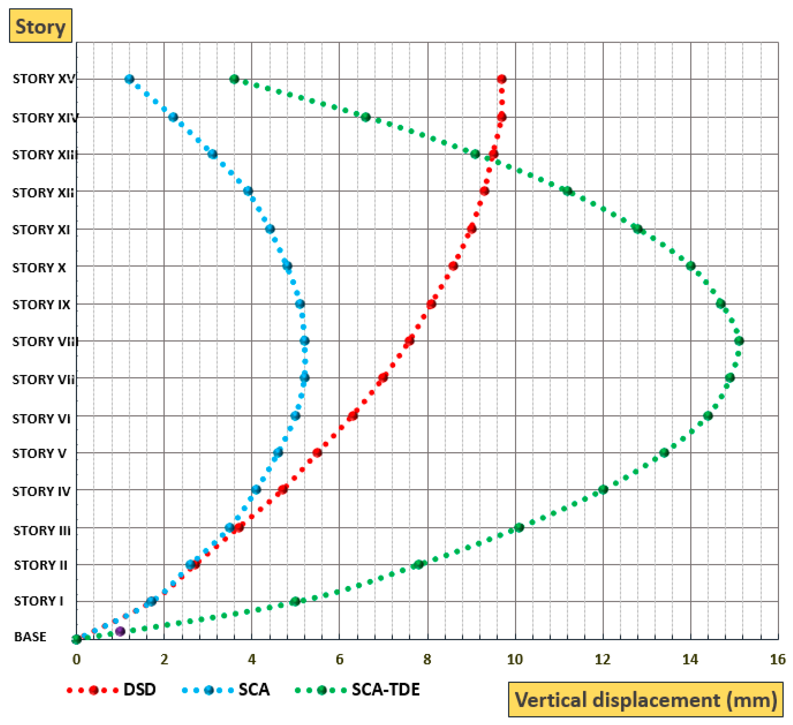
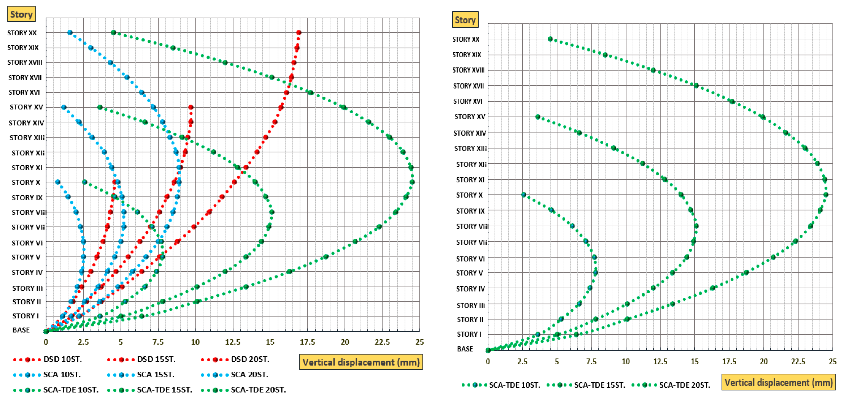
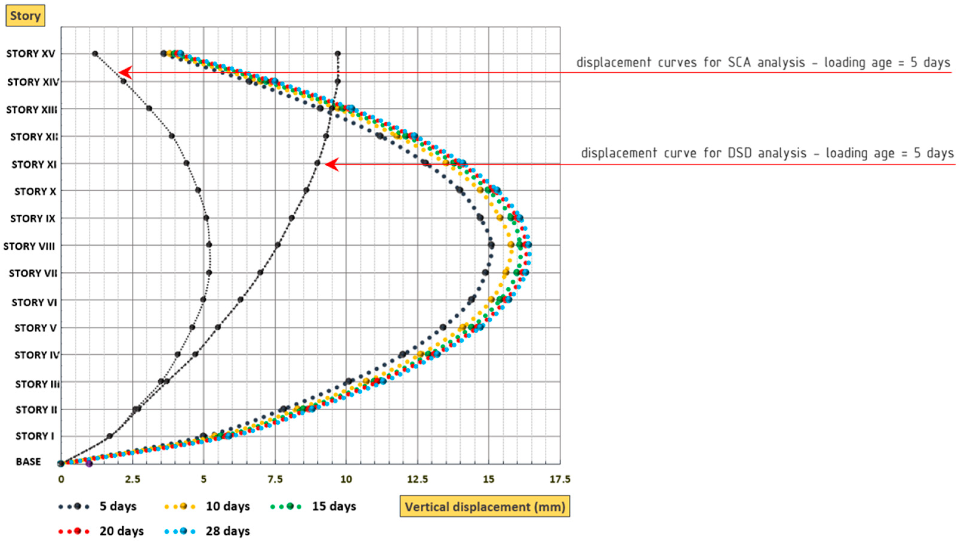
Dead and super-dead load analysis (DSD): time-dependent effects are neglected; the loads are applied theoretically after the whole structure is built; this is the most common analysis practically used by the designers, especially for low-rise structures, and can be static or dynamic.
(b)
Staged construction analysis (SCA): This is a method that generates static staged construction situations in a tailored fashion to simulate construction sequence loading; basically, the loads are applied after each story is constructed.
(c)
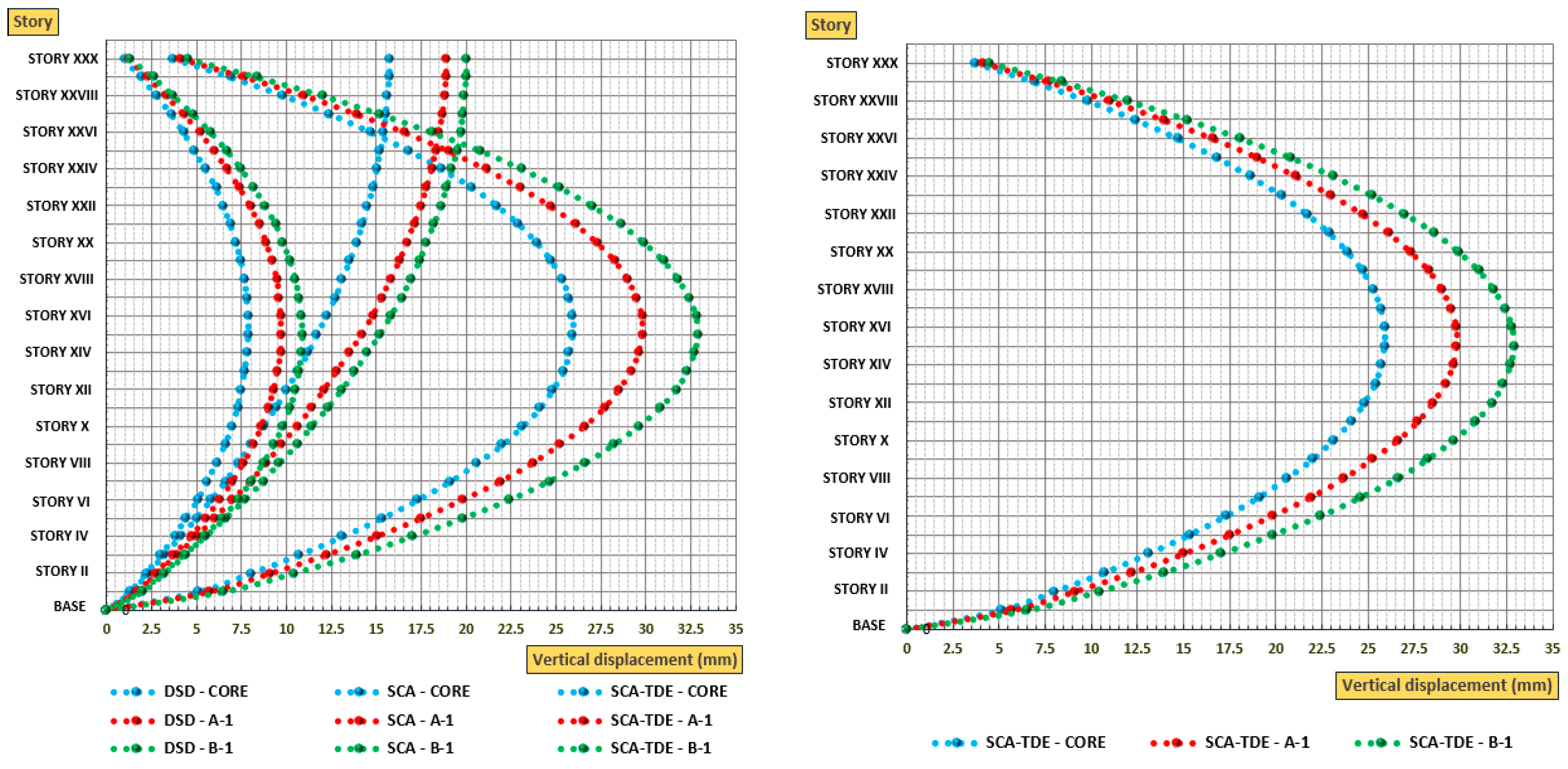
Staged construction analysis + time-dependent effects (SCA-TDE): This staged construction analysis allows for the creation of a building schedule that incorporates the addition or removal of structural components as well as the application of time-dependent behaviors such as creep, shrinkage, and concrete aging [31].
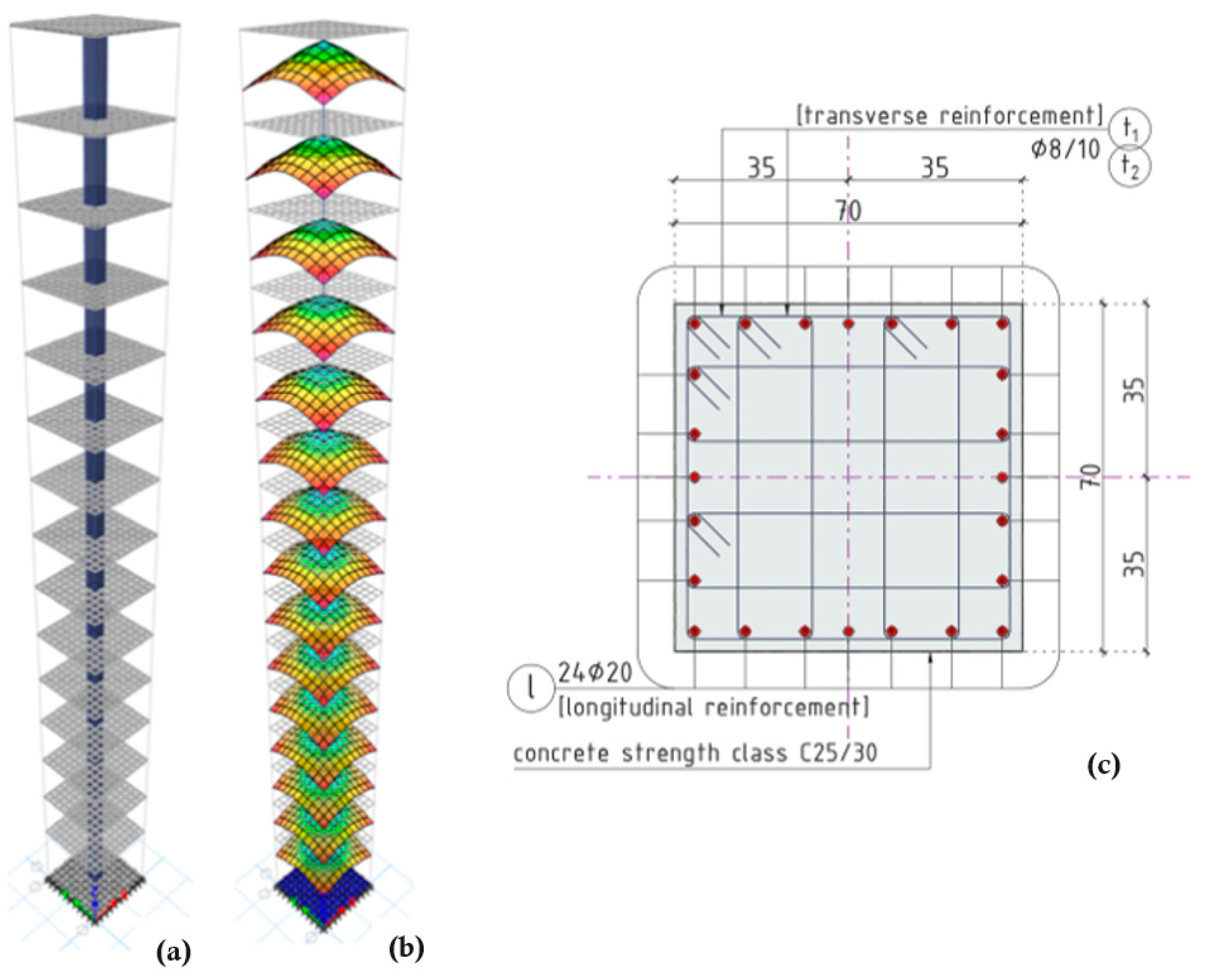
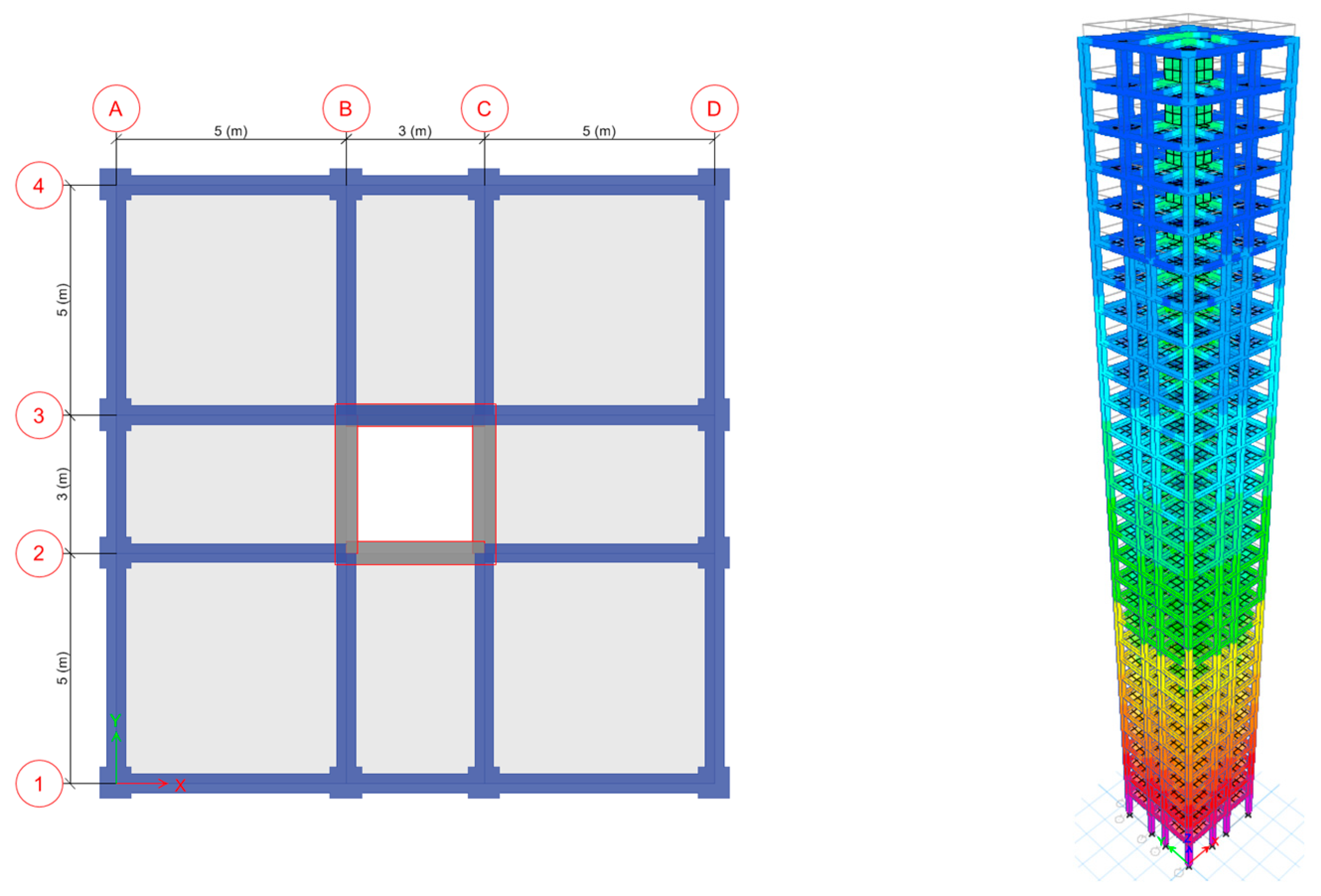
In this study, all three of them will be used, but it can be firmly concluded, even in the absence of exact data, that SCA-TDE is the appropriate one.

5. Case Study

A simple approach was chosen to evaluate the vertical shortening effects, consisting of two case studies. The first case serves as a calibration case for the analysis methods performed but also to verify and deduce how the main factors influence the vertical shortening, based on what was previously discussed. So, the case is based on a single vertical element made of reinforced concrete. This is because a single concrete element should work for any other element in a real structure, with only small differences that make sense because of the way the structure is built and how it acts. The second case will complete the conclusions, extending the judgment to problematics related to the main topic that can be verified in a three-dimensional reinforced concrete structure. In the first case, the vertical element has a constant cross-section, which supports tributary areas (5.0 × 5.0 m) in plan at each level. Soil–structure interaction is neglected. The bottom story height is 5.0 m, and the typical story height is 3.5 m. All the analyses account only for the self-weight of the structure and other dead or super-dead loads (Figure 4).
This means that the results are more qualitatively than quantitatively valid (although the influence of live loads is smaller compared to the influence of the others). The structure’s height, concrete characteristics, cross-section shape and dimensions, reinforcement, and loading time are parameters. Analysis is performed in ETABS and SAP 2000; for the SCA analysis, each story is considered a separate stage, while for the SCA-TDE analysis, in addition to this condition, each story is supposed to be constructed in 5 days, and after 3 days from the supposed pouring, the loads are applied. No comparisons are taken into account, as this would be the most practical solution to address the problem, and that is not what is being evaluated, although the software allows for modification of the deformed geometry based on the last-stage displacement values. Figure 5 presents the results performed for a 15-story structure. For sure, this is not the typical case of a high-rise structure, but it is an accepted simplification that does not affect the essence of this study. Other data inputs: column section (70 × 70) cm, longitudinal reinforcement 24Φ20 (1.54%), concrete strength class C25/30, dead load DL = 10.0 kN/m2, super-dead load SD = 2.0 kN/m2. The CEB 2010 Model is used to evaluate time-dependent effects for the SCA-TDE analysis (the model code does not present a significant importance related to the results interpretation point of view): relative humidity RH = 50%, cement type 42.5 N; each stage corresponds to a story with a construction duration of 5 days, while the loads are applied the 3rd day of the stage (the structure based on these inputs will serve as a reference, RS).
It can be noticed, as expected based on previous notice, that the results are quite different. The DSD analysis shows a constant increase in the vertical displacements, with a rapid gradient in the first part and a constant linearization towards the top level. The largest interstory displacements are at the bottom; the slope of the graph given by the tangent is flatter. The displacements of the SCA analysis follow a parabolic shape (remember that the axial deformation is given by the expression Δ = PL/EA), with maximum displacements in the center stories and maximum interstory equal to the DSD case. Finally, SCA-TDE analysis results follow the same parabolic shape as the previous case, but narrower and deeper (basically, the difference between them consists in the evaluation of time-dependent effects). A significant increase in the interstory displacements can be noticed, not only at the bottom, and most of the time, this is more problematic than the absolute displacement value encountered. SCA-TDE analysis for sure gives the best and most reliable results; conclusions are not based only on the displacement values. The relation between the analysis results might be different for other considered conditions.
The height of the structure or building was specified as a very important factor in the vertical shortening effects, and the presentation in Figure 6 can help provide a better understanding. Three structures are analyzed at 10 to 20 stories in height, keeping all the specified parameters listed above unchanged (RS) and having the same judgment bases. A progressive increase in the absolute displacements can be noticed, but not at a steady pace if carefully observed, reaching its maximum at the center of the stories. The interstory displacements increase too; even if time-dependent effects were neglected, the results can be justified by the principle of load vs. length for a simple compression element. These expected conclusions solidify the thesis that tall structures are more sensitive to vertical shortening.
The concrete strength class (herein according to EN 1992-1-1) [17] is a basic element of concrete structures, from every possible point of view. For further clarity, here is a brief summary of concrete grades and their applications:
Concrete C10 (C8/10): used for stabilizing subgrades; serves as a substrate and levelling material.
Concrete C25/30: known for its excellent strength parameters and is used in foundations, floors, and stairs.
Concrete C16/20: properties similar to C20/25 and C25/30; employed in building columns, foundations, or walls.
Concrete C45/55: structural concrete used for prefabricated elements, wells, or industrial flooring.
Concrete C50 (C55): enhanced compressive strength; suitable for structures like industrial tanks, bridges, or support columns.
These designations follow the updated PN-EN 206 standard across the European Union. Standardization simplifies material selection for builders, and ongoing research aims to improve concrete’s strength performance, leading to the introduction of new and enhanced products.
It influences the elastic and inelastic deformations of the structural elements. The elastic deformations are, among other factors, a function of the modulus of elasticity, while the inelastic ones depend on many characteristics of concrete listed more than once (it should be pointed out that neither of them is a direct function of its compressive strength but rather its composition and degree of hydration: creep and shrinkage decrease with decreasing water/cement ratio and decreasing cement content; creep also increases with increasing degree of hydration [24]. To get a better picture of how the vertical shortening effects are related to concrete strength class (considered as a parameter), the reference structure (RS), 15 stories, is further analyzed and discussed. The results are presented in Figure 7, with a focus on SCA-TDE analysis. Increasing the concrete strength [17] causes a reduction in the vertical displacements, both elastic and inelastic. The effects of this parameter are more visible in the inelastic range, although there is a smaller gradient for higher strength classes.
When the reference structure (RS) is analyzed as a function only of the structural vertical member cross-section size, maintaining the rest unchanged, a constant decrease in the displacements with the size occurs. This is more evident for the elastic displacements (bigger cross-section for the same load), while it is more difficult for the inelastic ones. The creep effects decrease progressively with the increase in member size, for the same reason as the elastic displacements, a bit faster, and due to the fact that every other affecting parameter is fixed. The shrinkage effects remain at the same values. This is reflected in the interstory displacements where the parabolas are shallower.
Volume-to-surface ratio, given as the ratio of the cross-section surface to its perimeter, and also the cross-section shape influence, are studied as other important factors. To this end, the cross-section is modified in shape and dimensions, starting from the (70 × 70) cm square column and ending at the (30 × 165) cm rectangle wall (the behavior of the element in the light of the analysis performed is not of importance), keeping almost the same surface but not the same perimeter, so increasing the exposed surface of the structural member in verticality, decreasing the volume-to-surface ratio from 17.50 cm for the (70 × 70) cm section to 12.7 cm for the (30 × 165) cm one. So, the elastic displacements are the same. Creep and shrinkage effects were supposed to increase in rate and in magnitude somehow because of the higher surface-to-volume ratio, which causes a more rapid dry and consequently shrink and drying creep, but they remained quite constant (the chart is not presented as a consequence). It is not excluded that for other analysis conditions, the results might be different; however, the parameters assumed show these results.
When there is a change only in dimensions but not in shape, as previously discussed (Figure 8), there is actually an increase in the volume-to-surface ratio, so, as expected, the shrinkage and creep decreased. The concrete’s size affects both the rate at which moisture escapes and the level of general control that the central core—which has a higher moisture content than the surface—provides. Since only the outside of the concrete is drying and the non-shrinking core is preventing it from shrinking, shrinkage should thus decrease as member size increases. Of course, the core will eventually dry out as well, but this will happen gradually and not with the same sudden impact that can be seen in the near future. Because there is no further influence of drying on creep, creep is less and independent of size if no drying occurs, as in the case of very large concrete members [32].
Construction time is a very important factor, especially for high-rise structures, and should be considered with the age of concrete at loading, a term part of the time-dependent effects expression [33]. The only factor that influences the deformation of loaded concrete over time is the creep stress. Changing the age at which the concrete is loaded has no effect on the amount of creep. In the event that concrete is loaded at a later age, which is determined by its pouring time, the creep strains should be less pronounced. This is due to the extended hydration period of the concrete, which facilitates the formation of more C-S-H bonds and enhances its strength and stiffness, thereby furnishing a more robust resistance to deformation.
As a result, the magnitude of the short-term change in creep strain should be greater for the concrete loaded at 28 days, when it is still acquiring strength, compared to the concrete loaded after that date, which, based on its composition, will have gained even more strength. Elastic displacements theoretically decrease as well. This was also verified by the simple structure of this study over shorter time periods. Each stage corresponding to a story now has a longer construction duration, 28 days, in order to have the possibility to vary the age of concrete when the loads will be applied, specifically, the 3rd day, 7th day, 14th day, 21st day, and 28th day (Figure 9).
The positive reinforcement restraining effect, according to the literature, is included in this study as well. Different reinforcement ratios are considered, from 0% (plain concrete) up to a theoretical 8% (basically, the maximum allowed by the design codes for a reinforced concrete column is 4%—not in the longitudinal bars overlapping zones). This variation is accompanied by a reduction in vertical displacement of up to 50% (Figure 10).
The influence of relative humidity is not presented graphically. However, it can be easily concluded based on the creep and shrinkage variations in Figure 3 that with the increase of this parameter’s values, both creep and shrinkage decrease, as a consequence of vertical shortening effects too.
The second case study consists of a 30-story reinforced concrete structure, dual system (Figure 11). This choice is appropriate and typical to enhance the possible differential shortening effects between the vertical structural elements with differential axial stiffness due to their primary function, possible redistributions of forces, especially in the horizontal elements. Input data: bottom story height is 5.0 m, typical story height is 3.5 m, column section (70 × 70) cm, column section (40 × 50) cm, wall thickness 50 cm, concrete strength class C25/30, reinforcement according to the design performed, dead load = 10.0 kN/m2, Super Dead L = 2.0 kN/m2.
The CEB 2010 Model is used to evaluate time-dependent effects: relative humidity RH = 50%, cement type 42.5 N; each stage corresponds to a story with a construction duration of 15 days, while the loads are applied on the 5th day of the stage. A single iteration is performed: three points are monitored corresponding to the A-1, B-1 columns, and the core corner.
As expected, the core’s shortening is less than the column’s shortening. Figure 12 shows that column B-1 has larger displacements because of the larger tributary area compared to A-1. The variation in axial force in the structural elements is very lightly influenced by vertical shortening, but such a thing cannot be expressed in relation to the bending moments and shear forces. An unneglectable redistribution occurs when the axial shortening is too relevant, resulting in an inversion of the bending moment diagram in beams [34], referring to the moment diagram according to the linear one-step analysis (DSD in this study).

6. Conclusions

In this paper, vertical shortening due to concrete time-dependent properties and effects in medium- to high-rise reinforced concrete structures is investigated while presenting, using a more objective approach, the variation in the main parameters that define these properties in synthetic form, so as to have a better understanding of the results. Three different analysis types were performed, emphasizing their specifics. The main conclusions are summarized as follows:
  • In order to capture the vertical shortening effects in a reinforced concrete structure, it is strongly recommended to perform, when software is used, a staged construction analysis plus time-dependent effects, since a one-step analysis for the complete structure always erroneously estimates these effects in qualitative and quantitative terms as well.
  • Although the staged construction analysis and time-dependent effects consider only the construction loads, the effects are comparable to the service loads. This is because the construction loads represent about 70% to 80% of the total service loads.
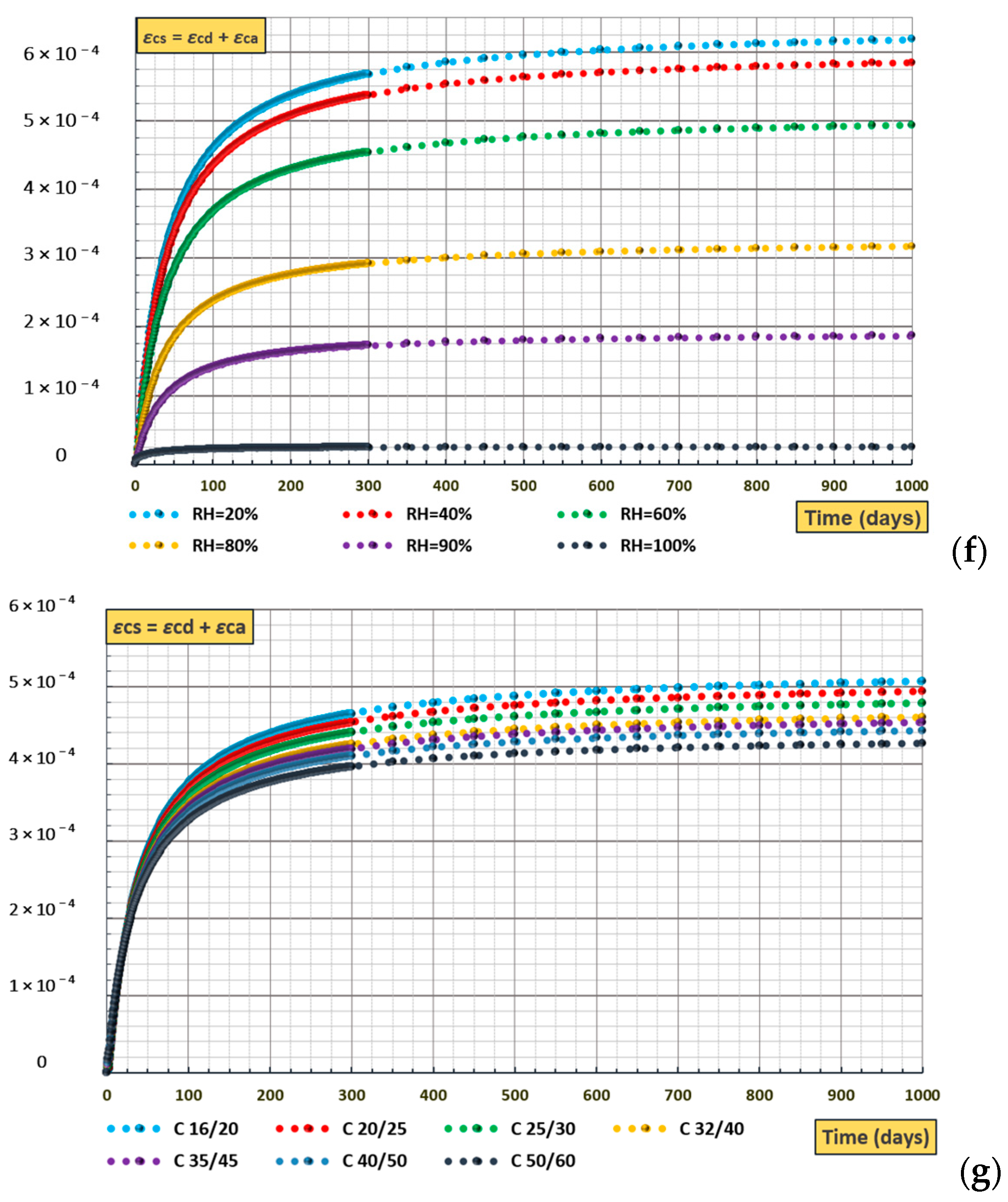
  • Vertical shortening effects are closely related to the creep and shrinkage of concrete, so their correct estimation and interpretation depend on the correct interpretation of these phenomena. At this point, one of the different models proposed by the technical literature or the design codes can be implemented within the analysis.
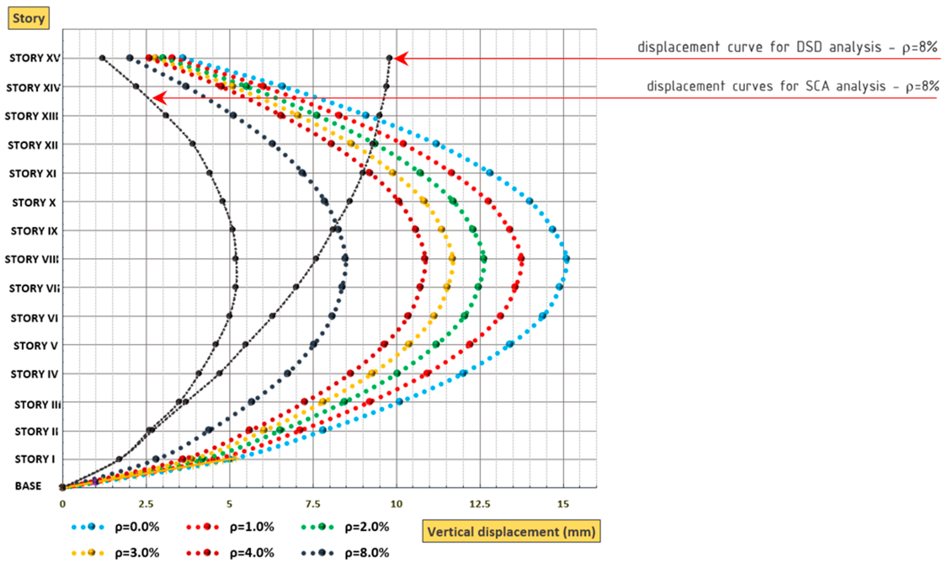
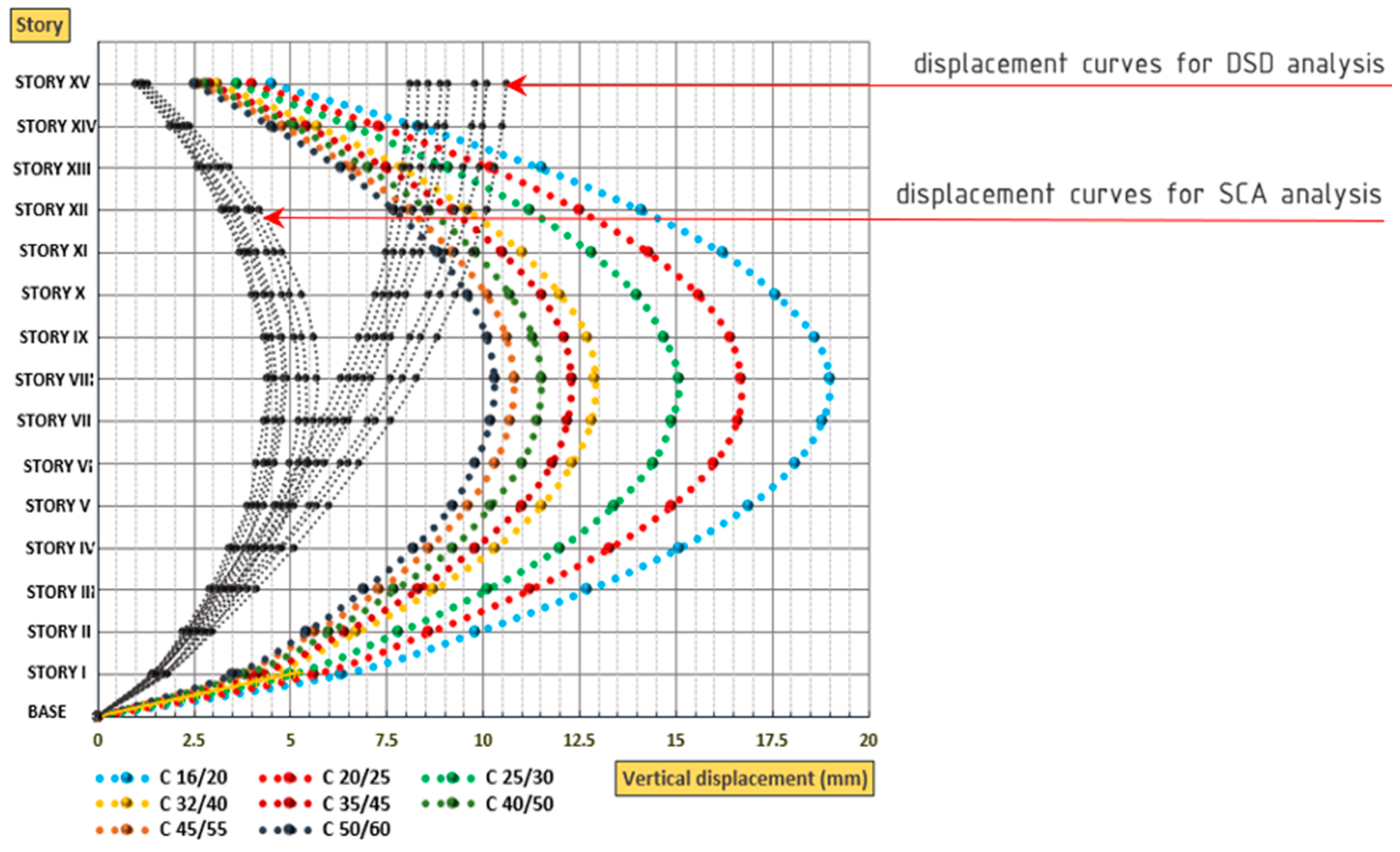
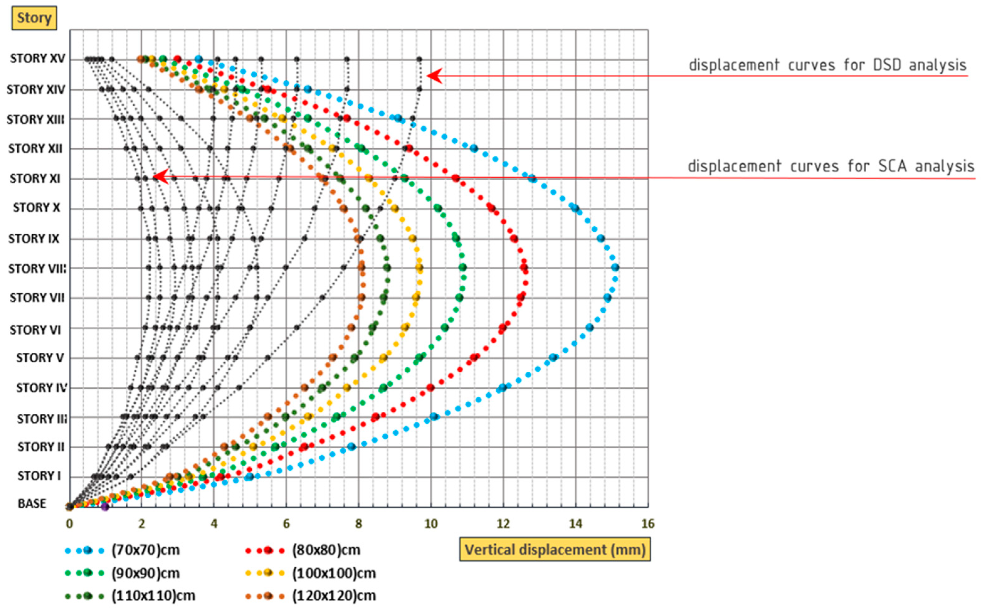
  • The case studies show that vertical shortening increases with the height of the structure and decreases with the increase of concrete strength, longitudinal reinforcement ratio, member size, volume-to-surface ratio, and age of the structure when loading occurs.
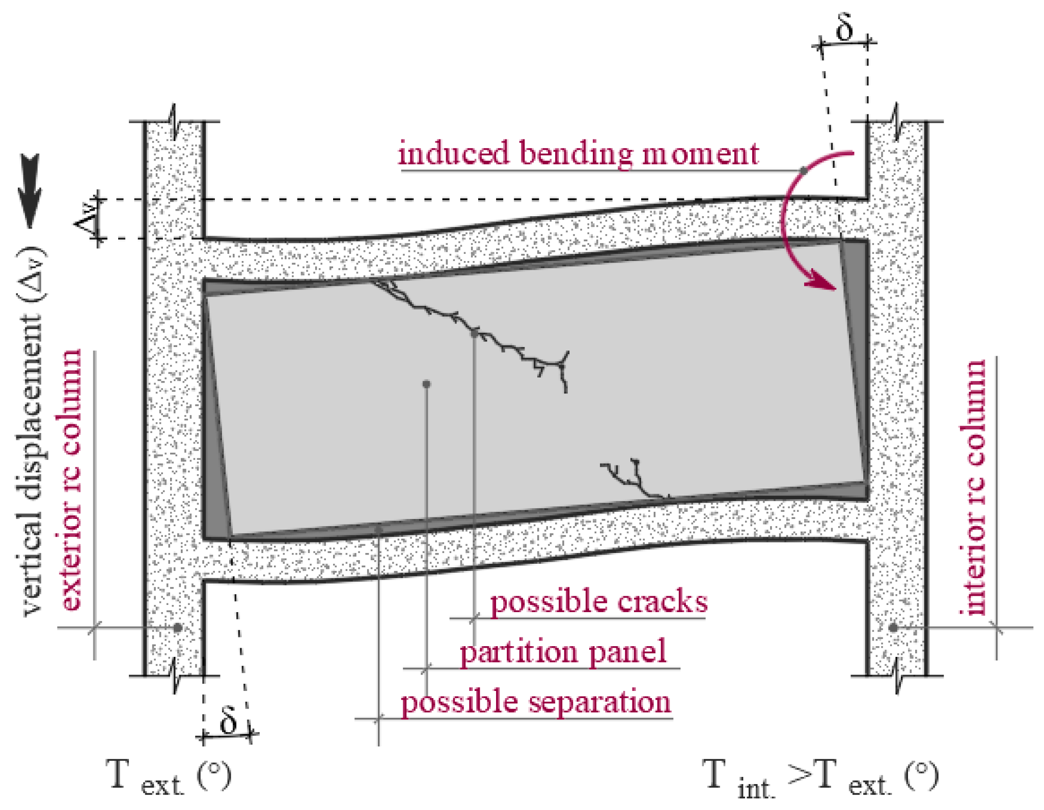
  • The concern is not only for the absolute value achieved for a single element or the whole structure but also for the large interstory displacements and, moreover, the possible differential shortening effects between the elements. The latter ones are more pronounced in structures with strong cores, as in Case 2, where differential column shortening occurs between the exterior columns and interior core. As a consequence, horizontal beams suffer considerable variation in shear forces and bending moments, while floors have noticeable differential displacement. Variation can also be noticed in column and wall axial forces, although it is negligible in this case.
  • Concrete time-dependent effects can be minimized by undertaking specific measures related to the mix design or treatment during and after casting, so the vertical shortening can be minimized too. Another economical, widely accepted, and applied alternative is to compensate for the calculated displacement during the casting of vertical structural elements.

Author Contributions

Conceptualization, E.D. and E.F.; methodology, M.G.; software, E.D.; validation, A.A. and M.G.; formal analysis, R.M.; writing—original draft preparation, E.D.; writing—review and editing, R.M. and A.A.; visualization, E.F.; supervision, A.A.; project administration, R.M.; All authors have read and agreed to the published version of the manuscript.

Funding

The authors would like to thank Technical University of Liberec on Student Grant Competition SGS-2024-3471.

Institutional Review Board Statement

Not applicable.

Data Availability Statement

The data that support the findings of this study are available upon request from the corresponding author.

Conflicts of Interest

The authors declare no conflicts of interest.

Nomenclatures

1. Acronyms
CEBComité Européen du Béton
ACIAmerican Concrete Institute
GLguideline
RHrelative humidity
SCA-TDEstaged construction analysis + time-dependent effects
SCAstaged construction analysis
DSDdead load (D) + super-dead load (SD)
EC 2Eurocode 2
2. Symbols/Parameters
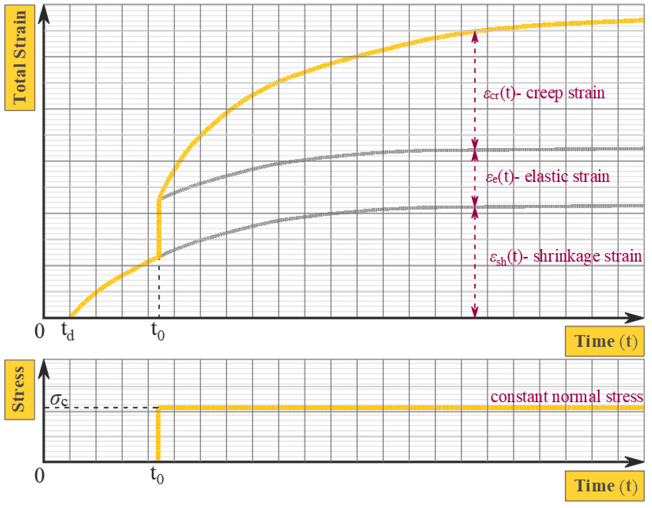
εeelastic strain
εshshrinkage effect strain
εcstotal concrete shrinkage strain
εcdconcrete drying shrinkage strain
εcaconcrete autogenous shrinkage strain
εcrcreep effect strain
εTtemperature effect strain
ε(t)total strain
Ec(to)elastic modulus of concrete at the time of loading
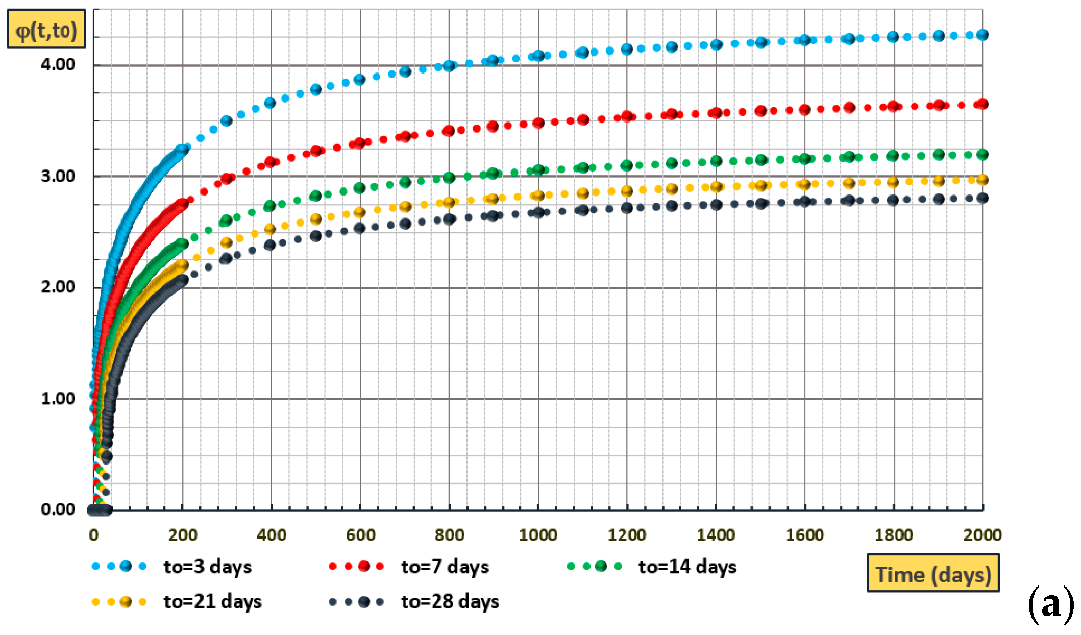
ϕ(t,to)creep coefficient

References

  1. Deneko, E.; Filaj, E. An Overview of Self-Healing Concrete in Sustainable Construction. J. Trans. Syst. Eng. 2023, 1, 110–119. [Google Scholar] [CrossRef]
  2. Hysenlliu, M.; Deneko, E. Capacity Evaluation and Spectral Analysis of Damaged Low-Rise Reinforced Concrete Building. J. Trans. Syst. Eng. 2023, 1, 120–130. [Google Scholar] [CrossRef]
  3. Choi, S.W.; Kim, Y.; Kim, J.M.; Park, H.S. Field Monitoring of Column Shortenings in a High-Rise Building during Construction. Sensors 2013, 13, 14321–14338. [Google Scholar] [CrossRef] [PubMed]
  4. Chen, Z.; Xu, Y.; Hua, J.; Zhou, X.; Wang, X.; Huang, L. Modeling Shrinkage and Creep for Concrete with Graphene Oxide Nanosheets. Materials 2019, 12, 3153. [Google Scholar] [CrossRef] [PubMed]
  5. Chen, P.; Zheng, W.; Wang, Y.; Chang, W. Analysis and Modelling of Shrinkage and Creep of Reactive Powder Concrete. Appl. Sci. 2018, 8, 732. [Google Scholar] [CrossRef]
  6. Nguyen, D.-B.; Lin, W.-S.; Liao, W.-C. Long-Term Creep and Shrinkage Behavior of Concrete-Filled Steel Tube. Materials 2021, 14, 295. [Google Scholar] [CrossRef] [PubMed]
  7. Lv, Z.; Liu, C.; Zhu, C.; Bai, G.; Qi, H. Experimental Study on a Prediction Model of the Shrinkage and Creep of Recycled Aggregate Concrete. Appl. Sci. 2019, 9, 4322. [Google Scholar] [CrossRef]
  8. Elnimeiri, M.; Patel, D. Long-term vertical shortening of reinforced concrete and composite high-rise structures. In Proceedings of the Seventh International Conference on Computing in Civil and Building Engineering, VOLS 1-4, Seoul, Republic of Korea, 19–21 August 1997; Choi, C.K., Kwak, H.G., Yun, C.B., Eds.; Techno-Press: Seoul, Republic of Korea, 1997; pp. 2329–2353. [Google Scholar]
  9. Moragaspitiya, P.; Thambiratnam, D.; Perera, N.; Chan, T. A numerical method to quantify differential axial shortening in concrete buildings. Eng. Struct. 2010, 32, 2310–2317. [Google Scholar] [CrossRef]
  10. Moragaspitiya, H.N.P.; Thambiratnam, D.P.; Perera, N.J.; Chan, T.H.T. Development of a vibration based method to update axial shortening of vertical load bearing elements in reinforced concrete buildings. Eng. Struct. 2013, 46, 49–61. [Google Scholar] [CrossRef]
  11. Correia, R.; Lobo, P.S. Simplified Assessment of the Effects of Columns Shortening on the Response of Tall Concrete Buildings. In Proceedings of the 2nd International Conference on Structural Integrity, ICSI 2017, Funchal, Portugal, 4–7 September 2017; Iacoviello, F., Moreira, P., Tavares, P.J.S., Eds.; Procedia Structural Integrity. Elsevier: Amsterdam, The Netherlands, 2017; Volume 5, pp. 179–186. [Google Scholar] [CrossRef]
  12. Como, M.; Lanni, G. Aseismic toughness of structures. Meccanica 1983, 18, 107–114. [Google Scholar] [CrossRef]
  13. Khan, F.R.; Fintel, M. Effects of column temperature, creep and shrinkage in tall structures. J. Proc. 1968, 65, 99–110. [Google Scholar] [CrossRef]
  14. Fintel, M.; Ghosh, S.K.; Iyengar, H. Column Shortening in Tall Structures: Prediction and Compensation; Portland Cement Association: Skokie, IL, USA, 1987. [Google Scholar]
  15. Fintel, M.; Khan, F.R. Effects of column creep and shrinkage in tall structures-prediction of inelastic column shortening. ACI J. Proc. 1969, 66, 957–967. [Google Scholar] [CrossRef]
  16. Sharma, R.K.; Maru, S.; Nagpal, A.K. Simplified procedure for creep and shrinkage effects in reinforced concrete frames. J. Struct. Eng. 2004, 130, 1545–1552. [Google Scholar] [CrossRef]
  17. Eurocode 2: Design of Concrete Structures Eurocodes: Building the Future. Available online: https://eurocodes.jrc.ec.europa.eu/EN-Eurocodes/eurocode-2-design-concrete-structures (accessed on 1 December 2023).
  18. Eurocode 8: Design of Structures for Earthquake Resistance Eurocodes: Building the Future. Available online: https://eurocodes.jrc.ec.europa.eu/EN-Eurocodes/eurocode-8-design-structures-earthquake-resistance (accessed on 1 December 2023).
  19. Gazzetta Ufficiale. Available online: https://www.gazzettaufficiale.it/eli/id/2008/02/04/08A00368/sg (accessed on 1 December 2023).
  20. ACI Code-318-14: Building Code Requirements for Structural Concrete and Commentary. Available online: https://www.concrete.org/store/productdetail.aspx?ItemID=318U14&Language=English&Units=US_Units (accessed on 1 December 2023).
  21. BS 8110-1: 1997; Structural Use of Concrete: Code of Practice for Design and Construction. Part 1. British Standard Institution: London, UK, 1997.
  22. Smith, B.S.; Coull, A. Tall Building Structures: Analysis and Design Wiley. Available online: https://www.wiley.com/en-us/Tall+Building+Structures%3A+Analysis+and+Design-p-9780471512370 (accessed on 1 December 2023).
  23. Cho, S.K.; Kim, H.S. Prediction, field measurement and compensation of column shortening in tall building. In Proceedings of the Korean Institute of Building Construction Conference, Seoul, Republic of Korea, 1 September 2003; pp. 143–146. Available online: https://koreascience.kr/article/CFKO200311921784581.page (accessed on 1 December 2023).
  24. Comite Euro-International Du Beton. Ceb-Fip Model Code 1990: Design Code; Thomas Telford Publishing: London, UK, 1993. [Google Scholar] [CrossRef]
  25. Comite Euro-International Du Beton. Fib Model Code for Concrete Structures 2010; Ernst & Sohn: Hoboken, NJ, USA, 2013; ISBN 978-3-433-03061-5. [Google Scholar]
  26. ACI 209.2R-08; Guide for Modeling and Calculating Shrinkage and Creep in Hardened Concrete. American Concrete Institute: Farmington Hills, MI, USA, 2008.
  27. Bazant, Z.P.; Baweja, S. Creep and shrinkage prediction model for analysis and design of concrete structures—Model B3. Mater. Struct. 1995, 28, 357–365. [Google Scholar] [CrossRef]
  28. Gardner, N.J. Design provisions for drying shrinkage and creep of normal-strength concrete. ACI Mater. J. 2001, 98, 159–167. [Google Scholar] [CrossRef]
  29. Gilbert, R.I. Time Effects in Concrete Structures; Elsevier: Amsterdam, The Netherlands, 1988; Available online: https://worldcat.org/title/18190828 (accessed on 1 December 2023).
  30. Parvin, A.; Alhusban, M. Lateral Deformation Capacity and Plastic Hinge Length of RC Columns Confined with Textile Reinforced Mortar Jackets. CivilEng 2021, 2, 670–691. [Google Scholar] [CrossRef]
  31. Wilson, E.L. CSI Analysis Reference Manual for SAP2000, ETABS and SAFE; Computers & Structures: Walnut Creek, CA, USA, 2016. [Google Scholar]
  32. Howells, R.W.; Lark, R.J.; Barr, B.I.G. A sensitivity study of parameters used in shrinkage and creep prediction models. Mag. Concr. Res. 2005, 57, 589–602. [Google Scholar] [CrossRef]
  33. Gilbert, R.I.; Ranzi, G. Time-Dependent Behaviour of Concrete Structures, 1st ed.; CRC Press: Cambridge, MA, USA, 2011. [Google Scholar] [CrossRef]
  34. Al Hasani, S.; Nasrellah, H.A.; Abdulraeg, A.A. Numerical Study of Reinforced Concrete Beam by Using ABAQUS Software. Int. J. Innov. Technol. Interdiscip. Sci. 2021, 4, 733–741. [Google Scholar] [CrossRef]
Figure 1. Schematic representation of possible vertical displacement consequences based on [12].
Civileng 05 00010 g001
Figure 2. Creep coefficient according to the CEB 2010 Model versus (a) concrete age at loading; (b) relative humidity (RH) for t = 28 days; (c) concrete strength class; (d) concrete compressive cylinder strength at loading age. Shrinkage strain versus (e) nominal size; (f) relative humidity; (g) concrete strength class.
Civileng 05 00010 g002aCivileng 05 00010 g002bCivileng 05 00010 g002c
Figure 3. Concrete specimen strain under sustained load (normal stress) [15].
Civileng 05 00010 g003
Figure 4. (a) Undeformed structure, (b) deformed structure, (c) column cross-section.
Civileng 05 00010 g004
Figure 5. Vertical displacements = f (height of the structure).
Civileng 05 00010 g005
Figure 6. Vertical displacements = f (height of the structure).
Civileng 05 00010 g006
Figure 7. Vertical displacements = f (concrete strength class).
Civileng 05 00010 g007
Figure 8. Vertical displacements = f (vertical member size).
Civileng 05 00010 g008
Figure 9. Vertical displacements = f (age of structure at loading).
Civileng 05 00010 g009
Figure 10. Vertical displacements = f (reinforcement ratio).
Civileng 05 00010 g010
Figure 11. Plan geometry and deformed shape of the structure—Case 2.
Civileng 05 00010 g011
Figure 12. Vertical displacements: core vs. columns—Case 2.
Civileng 05 00010 g012
Disclaimer/Publisher’s Note: The statements, opinions and data contained in all publications are solely those of the individual author(s) and contributor(s) and not of MDPI and/or the editor(s). MDPI and/or the editor(s) disclaim responsibility for any injury to people or property resulting from any ideas, methods, instructions or products referred to in the content.

